Renishaw OMP40-2 Installation Manual
Optical machine probe
Hide thumbs
Also See for OMP40-2:
- Quick start manual (178 pages) ,
- Manual (54 pages) ,
- Installation manual (42 pages)
Table of Contents
Advertisement
Advertisement
Chapters
Table of Contents

Related Manuals for Renishaw OMP40-2


Summary of Contents for Renishaw OMP40-2
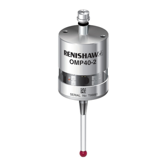
- Page 1 Installation guide H-4071-8504-04-A OMP40-2 optical machine probe...
- Page 2 © 2009–2015 Renishaw plc. All rights reserved. This document may not be copied or reproduced in whole or in part, or transferred to any other media or language, by any means, without the prior written permission of Renishaw plc. The publication of material within this document does not imply freedom from the patent rights of Renishaw plc.
-
Page 3: Table Of Contents
. . . . . . . . . . . . . . . . . . . . . . . . . . . . . . . . . . . . . . . . . . . . . . . . . . . . . . . . . . . 3 .1 Installing the OMP40-2 with an OMM-2 / OMI-2T / OMI-2H / OMI-2 / OMI / OMM . . . . . . . . . . 3 .1 OMM-2 / OMI-2T / OMI-2H / OMI-2 / OMI / OMM positioning . - Page 4 OMP40-2 installation guide Preparing the OMP40-2 for use . . . . . . . . . . . . . . . . . . . . . . . . . . . . . . . . . . . . . . . . . . . . . . . . 3 .3 Fitting the stylus .
-
Page 5: Before You Begin
Trade marks • neglected, mishandled or inappropriately used; RENISHAW and the probe symbol used in the RENISHAW logo are registered trade marks of • modified or altered in any way except with the Renishaw plc in the United Kingdom and other prior written agreement of Renishaw. -
Page 6: Patents
OMP40-2 installation guide Patents Features of the OMP40-2 probe, and other similar Renishaw probes, are the subject of one or more of the following patents and/or patent applications: EP 0695926 JP 3967592 EP 0974208 JP 4237051 EP 1130557 JP 4294101... -
Page 7: Ec Declaration Of Conformity
This equipment has been tested and found to comply with the limits for a Class A digital device, The use of this symbol on Renishaw products pursuant to part 15 of the FCC Rules. These limits and/or accompanying documentation indicates... -
Page 8: Safety
To reduce the risk of shipment delays, if you need to return the products to Renishaw for any reason, do not return any batteries. The OMP40-2 has a glass window. Handle with care if broken to avoid injury. - Page 9 Optical safety This product contains LEDs that emit both visible and invisible light. OMP40-2 is ranked Risk Group: Exempt (safe by design). The product was evaluated and classified using the following standard: BS EN 62471:2008...
- Page 10 OMP40-2 installation guide This page intentionally left blank...
-
Page 11: Omp40-2 Basics
OMP40-2 basics Introduction Getting started Three multicolour probe LEDs provide visual The OMP40-2 is an optical machine tool probe indication of selected probe settings. suitable for use on small to medium machining and multi-tasking centres. It is designed to resist For example: optical interference, false triggering and shock. -
Page 12: Trigger Logic
5 seconds and then replacing them, which activates the Trigger Logic review sequence. Probe modes The OMP40-2 probe can be in one of three modes: Standby mode – probe is waiting for a switch-on signal. - Page 13 OMP40-2 switch-on method OMP40-2 switch-off method Switch-on time Switch-on options are configurable Switch-off options are configurable Optical on Optical off Legacy (start filter off): 0.5 seconds Optical switch-on is commanded by Optical switch-off is commanded by Legacy (start filter on): machine input.
-
Page 14: Enhanced Trigger Filter
Probes subjected to particular forms of light interference may accept spurious start signals. Optical power The OMP40-2 can be operated in either ‘Legacy’ Where the separation between the OMP40-2 or ‘Modulated’ optical transmission mode. and the OMM-2 with OSI / OMI-2 / OMI-2T /... -
Page 15: Omp40-2 Dimensions
OMP40-2 dimensions Window 50 (1.97) 19 (0.75) Battery cassette A range of probe-ready shanks is available from Renishaw M4 stylus 12.5° 12.5° XY overtravel Transmit diode Probe status LED Receive diode 50 (1.97) Dimensions given in mm (in) Stylus overtravel limits Stylus length ±X/±Y... -
Page 16: Omp40-2 Specification
±12.5° +Z plane 6 mm (0.24 in) Environment IP rating IPX8 (EN/IEC 60529) IK rating (OMP40-2 and IK01 (EN/IEC 62262) [for glass window] OMP40-2 LS) IK rating (OMP40M) IK02 (EN/IEC 62262) [for glass window] Storage temperature -25 °C to +70 °C (-13 °F to +158 °F) Operating temperature +5 °C to +55 °C (+41 °F to +131 °F) -
Page 17: Typical Battery Life
Typical battery life Modulated transmission 2 x ½AA 3.6 V LTC batteries Standard power Low power (typical) Standby life 430 days 5% usage 140 days 180 days Continuous use 250 hours 350 hours Legacy transmission 2 x ½AA 3.6 V LTC batteries Standard power Low power (typical) - Page 18 OMP40-2 installation guide This page intentionally left blank...
-
Page 19: System Installation
System installation Installing the OMP40-2 with an OMM-2 / OMI-2T / OMI-2H / OMI-2 / OMI / OMM OMI / OMI-2 / OMI-2T / OMP40-2 probe OMI-2H OMM-2 MI 12 interface unit or MI 12-B interface unit Workpiece CNC machine... -
Page 20: Omm-2 / Omi-2T / Omi-2H / Omi-2 / Omi / Omm Positioning
The probe and OMM-2 / OMI-2T / OMI-2H / OMI-2 diodes must be in each other’s field of view and within the performance envelope shown. The OMP40-2 performance envelope is based on the OMM-2 / OMI-2T / OMI-2H / OMI-2 being at 0° and vice versa. -
Page 21: Preparing The Omp40-2 For Use
Preparing the OMP40-2 for use Fitting the stylus 1.8 Nm – 2.2 Nm (1.3 lbf.ft – 1.6 lbf.ft) M-5000-3707... -
Page 22: Stylus Weak Link
OMP40-2 installation guide Stylus weak link 1.8 Nm – 2.2 Nm NOTE: Must be used with steel styli. For optimum (1.3 lbf.ft – 1.6 lbf.ft) metrology performance do not use a weak link with ceramic or carbon fibre styli. Fitting a stylus with a weak link onto the... -
Page 23: Installing The Batteries
Installing the batteries NOTES: See Section 5, “Maintenance” for a list of suitable battery types. If dead batteries are inadvertently inserted, the LEDs will remain a constant red. Do not allow coolant or debris to enter the battery compartment. When inserting batteries, check that the battery polarity is correct. -
Page 24: Mounting The Probe On A Shank
OMP40-2 installation guide Mounting the probe on a shank 2.0 mm A/F × 2 2.0 mm A/F × 4 0.5 Nm – 1.5 Nm (0.4 lbf.ft – 1.1 lbf.ft) 0.5 Nm – 1.5 Nm (0.4 lbf.ft – 1.1 lbf.ft) -
Page 25: Stylus On-Centre Adjustment
Stylus on-centre adjustment NOTES: If a probe and shank assembly is dropped, it must be rechecked for correct on-centre adjustment. × 4 Do not hit or tap the probe to achieve on-centre adjustment. 360° 1.5 Nm – 2.2 Nm × 2 (1.1 lbf.ft –... -
Page 26: Calibrating The Omp40-2
OMP40-2 installation guide Calibrating the OMP40-2 Three different operations are to be used when calibrating a probe. They are: Why calibrate a probe? • calibrating either in a bored hole or on a turned diameter of known position; A spindle probe is just one component of the measurement system which communicates with •... -
Page 27: Trigger Logic
Trigger Logic™ Reviewing the probe settings LED check > 5 s Key to the symbols LED short flash LED long flash Switch-off method Optical off Short timeout Medium timeout Long timeout 12 s 33 s 134 s Enhanced trigger filter 0 ms 10 ms Optical transmission method... -
Page 28: Probe Settings Record
✔ On (10 ms) Optical transmission Legacy (start filter off) method Legacy (start filter on) Modulated PROBE 1 ✔ Modulated PROBE 2 Modulated PROBE 3 Optical power Standard ✔ Factory settings are for kit (A-4071-2001) only. OMP40-2 serial no ........ - Page 29 This page intentionally left blank...
-
Page 30: Changing The Probe Settings
OMP40-2 installation guide Changing the probe settings Insert the batteries or, if they have already been > 5 s installed, remove them for five seconds and then refit them. Following the LED check, immediately deflect the stylus and hold it deflected until five red flashes have been observed (if the battery power is low, each red flash will be followed by a blue flash). - Page 31 Optical power Standard Return to “Switch-off method” New settings complete...
-
Page 32: Operating Mode
OMP40-2 installation guide Operating mode LEDs LEDs LEDs flashing flashing flashing green Probe status LEDs LED colour Probe status Graphic hint Flashing green Probe seated in operating mode Flashing red Probe triggered in operating mode Flashing green and blue Probe seated in operating mode – low battery Flashing red and blue Probe triggered in operating mode –... -
Page 33: Maintenance
Further dismantling and repair of Renishaw transmission. equipment is a highly specialised operation, which must be carried out at an authorised Renishaw Service Centre. Equipment requiring repair, overhaul or attention under warranty should be returned to your supplier. -
Page 34: Changing The Batteries
OMP40-2 installation guide Changing the batteries CAUTIONS: Do not leave dead batteries in the probe. When changing batteries, do not allow coolant or debris to enter the battery compartment. When changing batteries, check that the battery polarity is correct. Take care to avoid damaging the battery cassette gasket. - Page 35 NOTES: After removing the old batteries, wait more than 5 seconds before inserting the new batteries. Do not mix new and used batteries or battery types, as this will result in reduced life and damage to the batteries. Always ensure that the cassette gasket and mating surfaces are clean and free from dirt before reassembly.
- Page 36 OMP40-2 installation guide This page intentionally left blank...
-
Page 37: Omp40M System
OMP40M system OMP40M system OMP40M is a special modular version of OMP40-2 which has an enhanced window and metal battery cassette. It enables probe inspection of part features inaccessible to OMP40-2, by fitting selected adaptors and extensions as shown below. -
Page 38: Omp40M Screw Torque Values
OMP40-2 installation guide OMP40M screw torque values 10 Nm to 12 Nm (7.37 lbf.ft to 8.84 lbf.ft) 10 Nm to 12 Nm (7.37 lbf.ft to 8.84 lbf.ft) -
Page 39: Omp40-2Ls System
OMP40-2LS system Introduction The OMP40-2LS probe has a reduced switch-on range when compared to an OMP40-2 probe. Performance envelope with an OMM-2 / OMI-2T / OMI-2H / OMI-2 (modulated transmission) 75° 75° 60° 60° 45° OMM-2 45° OMI-2T OMP40-2LS 30°... - Page 40 OMP40-2 installation guide This page intentionally left blank...
-
Page 41: Fault-Finding
Batteries inserted incorrectly. Check battery insertion/polarity. Optical/magnetic interference. Check for interfering lights or motors. Transmission beam obstructed. Check that the OMP40-2 and receiver windows are clean and remove any obstruction. Probe out of range/not aligned with Check alignment and if receiver receiver. - Page 42 OMP40-2 installation guide Symptom Cause Action Machine stops Optical communication obstructed. Check interface/receiver and unexpectedly during a remove obstruction. probing cycle. Interface/receiver/machine fault. Refer to interface/receiver/ machine user’s guide. Dead batteries. Change batteries. False probe trigger. Enable enhanced trigger filter.
- Page 43 Symptom Cause Action Poor probe repeatability Debris on part or stylus. Clean part and stylus. and/or accuracy. Poor tool change repeatability. Redatum probe after each tool change. Loose probe mounting on shank Check and tighten as appropriate. or loose stylus. Excessive machine vibration.
- Page 44 OMP40-2 installation guide Symptom Cause Action Probe fails to switch off. Wrong switch-off mode selected. Reconfigure to optical off mode. Optical/magnetic interference. Check for interfering lights or motors. Consider removing the interfering source. Probe is inadvertently switched Check position of receiver.
-
Page 45: Parts List
Parts list Item Part number Description OMP40-2 A-4071-2001 OMP40-2 probe with batteries, tool kit and quick-start guide (set to optical on / optical off) – modulated transmission, PROBE 1 start. OMP40-2 A-4071-2002 OMP40-2 probe with batteries, tool kit and quick-start guide (set to optical on / time off 134 sec) –... - Page 46 A-2063-7600 MA4 90° adaptor assembly. A-2063-6098 LP2 probe complete with two C spanners and TK1 tool kit. Publications. These can be downloaded from our website at www.renishaw.com. OMP40-2 A-4071-8500 Quick-start guide: for rapid set-up of the OMP40-2 probe (includes CD with installation guides).
- Page 47 This page intentionally left blank...
- Page 48 Renishaw plc +44 (0)1453 524524 +44 (0)1453 524901 New Mills, Wotton-under-Edge, uk@renishaw.com Gloucestershire, GL12 8JR United Kingdom www.renishaw.com For worldwide contact details, visit www.renishaw.com/contact *H-4071-8504-04* Issued: 05.2015 Part no. H-4071-8504-04-A © 2009-2015 Renishaw plc...
Need help?
Do you have a question about the OMP40-2 and is the answer not in the manual?
Questions and answers