
Related Manuals for Renishaw AM250


Summary of Contents for Renishaw AM250
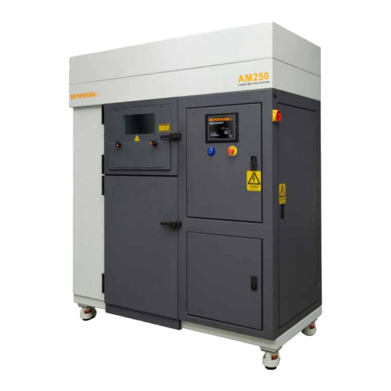
- Page 1 User guide AM250 H-5800-0704-03-B Renishaw additive manufacturing system AM250 Laser melting machines for Additive Manufacturing in metals...
- Page 2 Renishaw plc. Disclaimer Renishaw has made considerable efforts to ensure the content of this document is correct at the date of publication but makes no warranties or representations regarding the content. Renishaw excludes liability, howsoever arising, for any inaccuracies in this document.
- Page 3 Additionally, the system must only be operated by staff who have followed a Renishaw approved training course, and in accordance with the instructions and advice contained in this manual. If in doubt about the particular requirements of the Renishaw AM machine for a specific material, please contact us for advice and guidance.
-
Page 4: Table Of Contents
Flammability ........................27 7.11 Fire-fighting ........................27 7.12 Handling and processing ....................28 7.13 Storage ..........................28 7.14 Spills ..........................29 7.15 Metal powder safety checklist ..................29 H-5800-0704-03-B - © 2014 - User guide - Renishaw additive manufacturing system AM250... - Page 5 Laser ..........................50 12.5 Chiller ..........................50 12.6 Beam aperture protective window .................. 50 12.7 Viewing window ......................51 12.8 Loading metal powder using powder flasks ..............51 H-5800-0704-03-B - © 2014 - User guide - Renishaw additive manufacturing system AM250...
- Page 6 Front overflow ......................... 79 21. Safe change filter ................... 81 21.1 Installing a new filter element ..................81 21.2 Installing the safe change filter on the machine.............. 83 H-5800-0704-03-B - © 2014 - User guide - Renishaw additive manufacturing system AM250...
- Page 7 30. Safe change filter assembly removal ............132 31. Changing the filter element ................. 135 31.1 Safe change filter disassembly ..................135 32. Hopper and dosing mechanism removal/exchange ........138 H-5800-0704-03-B - © 2014 - User guide - Renishaw additive manufacturing system AM250...
- Page 8 33.2 WEEE directive ......................147 33.3 Batteries ........................147 34. Appendix A – substrate drawing ..............148 35. Appendix B – part numbers of spares ............149 H-5800-0704-03-B - © 2014 - User guide - Renishaw additive manufacturing system AM250...
-
Page 9: Scope Of Supply
Optional items Furnace Bead blast unit Replacement sieve mesh Additional material hopper Additional material doser Additional filter housing Additional material flasks and valves Additional Magics software modules H-5800-0704-03-B - © 2014 - User guide - Renishaw additive manufacturing system AM250... -
Page 10: Warranty And Liability
When ordering spare parts please quote the following: Description of the spare part and its part number, if known. Equipment name and model. Serial number. Year of manufacture. H-5800-0704-03-B - © 2014 - User guide - Renishaw additive manufacturing system AM250... -
Page 11: Introduction
Introduction The Renishaw AM250 is a complex piece of manufacturing equipment and must be used correctly to ensure optimum performance. It must not be used by untrained staff who have not completed a Renishaw approved training course. Definitions The following definitions are used throughout this manual: The client or end user is the company responsible for purchasing or using the equipment. -
Page 12: Text Structure
Controls and function keys are written between <angled brackets>. Wildcards for filenames are written in <angled brackets> and in italics. H-5800-0704-03-B - © 2014 - User guide - Renishaw additive manufacturing system AM250... -
Page 13: Safety Warnings In This Manual
Indicates important information that requires your attention. WARNING Danger of asphyxiation. CAUTION Risk of injury when handling heavy object. CAUTION Use of pressurised water fire extinguishers not recommended. H-5800-0704-03-B - © 2014 - User guide - Renishaw additive manufacturing system AM250... -
Page 14: Training Schedule
Training schedule Renishaw provides a basic level of training to operate the equipment safely. Renishaw also offers extended training courses for operators and process engineers. Please refer to this manual and the training documentation supplied as part of the user training course, that all users must be complete before using the system. -
Page 15: Contact Details
(see Figure 15A) and the software version on the start screen (Figure 15B). Figure 15A Build information plate Figure 15B Software information Additional support can be sought by contacting your local Renishaw office. See: http://www.renishaw.com/en/worldwide-locations--6438 H-5800-0704-03-B - © 2014 - User guide - Renishaw additive manufacturing system AM250... -
Page 16: Safety
Operation of the Renishaw AM250 is only permitted by operators who have completed a Renishaw approved training program. Safety interlocks and circuits must NEVER be overridden. H-5800-0704-03-B - © 2014 - User guide - Renishaw additive manufacturing system AM250... -
Page 17: Basic Safety Measures
PPE and other equipment as the components are removed from the machine. If in doubt about the health and safety issues and your legal obligations, our recommendation is to engage the services of a competent person. H-5800-0704-03-B - © 2014 - User guide - Renishaw additive manufacturing system AM250... -
Page 18: Safety Signs
1000 nm to 1100 nm. Failure to do so may result in permanent irreparable eye damage. Any maintenance MUST be carried out by a suitably qualified person. H-5800-0704-03-B - © 2014 - User guide - Renishaw additive manufacturing system AM250... -
Page 19: Laser Warning Labelling
Laser warning labelling In order to comply with international standards, the Renishaw AM250 carries various safety warning labels regarding the emission of laser light. These labels form part of the safety information and it is recommended that users regularly (we suggest weekly) check the condition and presence of the labels in the locations shown in the following images. - Page 20 Top Door (Figure 20B). Figure 20B Interlocked housing label Class 1 “general classification label”, displayed to the right of the serial plate (Figure 20C). Figure 20C General classification label H-5800-0704-03-B - © 2014 - User guide - Renishaw additive manufacturing system AM250...
- Page 21 Figure 21B Protective housing label Class 4 “Protective housing labels”, displayed in line with the right edge of the hopper seal plate (Figure 21C). Figure 21C Protective housing label H-5800-0704-03-B - © 2014 - User guide - Renishaw additive manufacturing system AM250...
- Page 22 Class 4 “Protective housing labels”, placed in between the two fans closest to the front of the machine, directly on the top cover (Figure 22B). Figure 22B Protective housing label H-5800-0704-03-B - © 2014 - User guide - Renishaw additive manufacturing system AM250...
-
Page 23: General Safety Instructions
General safety instructions Risk assessments have been carried out to ensure that the Renishaw AM250 operates in a safe manner under normal defined operating conditions. The Renishaw AM250 conforms to relevant European standards and legislation in force at the time that the equipment was manufactured. -
Page 24: Normal Operation
Normal operation The Renishaw AM250 may only be started up from the area directly in front of the touch screen. Starting the machine from any other location is unsafe. During equipment and ancillary equipment operation, no safety devices may be removed or disabled. -
Page 25: Personal Protective Equipment (Ppe)
It is recommended that the use of other metal powders is discussed in advance with Renishaw to ensure safe processing, and the appropriate processing parameters are used, if available. Renishaw powders have been tested and validated for use in the AM250 machine. Successful part production depends upon the machine being properly serviced and maintained, and the use of Renishaw process parameters. -
Page 26: Improper Use
The use of non-approved or highly toxic metal powders and other hazardous substances not approved by Renishaw. For machine servicing purposes, Renishaw requires full knowledge of all the materials that have been used in the machine in order to protect our staff. -
Page 27: Toxicity/Personnel Exposure
As a general rule, it is unsafe to use water or pressurised fire extinguishers, as there is a risk that the metal powder could be forced into suspension. H-5800-0704-03-B - © 2014 - User guide - Renishaw additive manufacturing system AM250... -
Page 28: Handling And Processing
Generally, metal powder should be stored in a cool dry place in hermetically sealed non- flammable containers away from ignition sources. Bulk storage should be in accordance with local building and fire codes. Consider zone-classified storage cabinets. H-5800-0704-03-B - © 2014 - User guide - Renishaw additive manufacturing system AM250... -
Page 29: Spills
Have you supplied the local fire protection agency with a copy of the material SDS? Have area personnel been trained to handle small metal powder fires? H-5800-0704-03-B - © 2014 - User guide - Renishaw additive manufacturing system AM250... -
Page 30: Residual Dangers, Maintenance And Protective Measures
7.16 Residual dangers, maintenance and protective measures Ensure that local risk assessments have been carried out to ensure that the Renishaw AM250 machine operates in a safe manner under normal defined operating conditions. -
Page 31: Safety During Maintenance
Cordon off access to the work area of the machine. Replace worn or damaged parts. Only use original replacement parts. H-5800-0704-03-B - © 2014 - User guide - Renishaw additive manufacturing system AM250... -
Page 32: Work On Electrical Equipment
Some components may be stopped in positions which make them unsafe. Sealed pneumatic lines will remain pressurised. H-5800-0704-03-B - © 2014 - User guide - Renishaw additive manufacturing system AM250... -
Page 33: Hazards Due To Unexpected Malfunctions
ATEX regulations and DSEAR require risk assessments to determine the required area zone classification BEFORE putting the equipment into use. H-5800-0704-03-B - © 2014 - User guide - Renishaw additive manufacturing system AM250... -
Page 34: Identifiable Ignition Sources
All operators and any authorised personnel must wear anti-static boots and clothing. Only tools and other items that are suitable for the zone classification may be used in that area. H-5800-0704-03-B - © 2014 - User guide - Renishaw additive manufacturing system AM250... -
Page 35: Technical Specifications, Services And Installation Requirements
~30 L/h – 50 L/h average Argon quality 5 ppm or better (99.9995% pure) Continuous noise pressure level 65 dB Maximum noise pressure level (temporary) 67 dB Table 35A AM250 Technical specifications H-5800-0704-03-B - © 2014 - User guide - Renishaw additive manufacturing system AM250... -
Page 36: Installation Requirements
Check that the lifting plant capacity, floor condition and load-bearing capacity along the access route is smooth and adequate to support the weight of the equipment and any transporting device. The AM250 has a gross weight of 1225 When lifting the centre of gravity is biased towards the build chamber Check that the installation site has been prepared in advance to accept the installation. - Page 37 The optional accessories require the following minimum clearances: (All dimensions in mm). It is possible to locate the AM250 and all the accessories in a room of 4000 mm × 8000 mm. An example on the following page shows all the necessary services.
- Page 38 Figure 38A An example floor layout H-5800-0704-03-B - © 2014 - User guide - Renishaw additive manufacturing system AM250...
- Page 39 HRS024-A-20-T chiller 230/400 Vac 50 Hz 3 PH Sieve station MS 400 230 Vac 50 Hz 13 A 1 PH Ultra-sonic unit Table 39B Recommended electrical specification H-5800-0704-03-B - © 2014 - User guide - Renishaw additive manufacturing system AM250...
-
Page 40: Inert Gas
Electrical connection for the AM250 – circuit breaker within the distribution board to be D rated and able to supply 16 A. Cable for the AM250 to be armoured, and armoured sheath to be earthed. Sieve to be wired in armoured cable and in accordance with the Russell Finex Installation Guide. -
Page 41: Oxygen Level Monitoring Within The Room
50 m³/h. Network connection and build preperation PC The Renishaw AM250 requires a connection to the file preparation PC. In cases where the machine cannot be connected to the network, a separate dedicated network card should be installed in the file preparation PC. -
Page 42: Transport And Machine Relocation
Microsoft Windows 7 (Professional) 64 bit. Transport and machine relocation If your AM250 is to be moved to an alternative production facility or resold, Renishaw is happy to assist and advise. With this in mind, please inform us at your earliest convenience. -
Page 43: Safety Precautions For End Users And Operators
European Committee for Standardisation for EN (European Norm) standards, or Laser Institute of America for ANSI (American National Standards Institute) standards. H-5800-0704-03-B - © 2014 - User guide - Renishaw additive manufacturing system AM250... -
Page 44: Fire Precautions
Never use compressed air to clean spills or residual traces of combustible metal powder. This could cause an explosive cloud to form. H-5800-0704-03-B - © 2014 - User guide - Renishaw additive manufacturing system AM250... -
Page 45: Inert Gas Safety
(<19.5%) indicated by a visible and audible warning device! The Renishaw AM250 is designed to consume minimal amounts of inert gas. It is possible to use either argon or nitrogen to create an inert atmosphere. As a consequence of this low gas consumption, our recommendation is to use argon gas, which offers the additional benefit of being compatible with both non-reactive and reactive materials. -
Page 46: Substrate Materials
– this is typically only when very large and particularly dense parts are fabricated. If in doubt contact the applications team. Appendix A for standard substrate drawing. H-5800-0704-03-B - © 2014 - User guide - Renishaw additive manufacturing system AM250... -
Page 47: Machine Controls And Features Overview
Lockable glove-box Emergency stop button Chamber access gloves Operator touch screen interface (HMI) Main electrical isolator Reset button Laser safe viewing window Electrical access panel door Adjustable feet H-5800-0704-03-B - © 2014 - User guide - Renishaw additive manufacturing system AM250... -
Page 48: Left-Hand User Access Door Am250
Argon connection to machine circuit Gas recirculation pump Left-hand access door for safe change filter Large overflow flask Powder level sensor Small powder flask sensor – warning hot surface H-5800-0704-03-B - © 2014 - User guide - Renishaw additive manufacturing system AM250... -
Page 49: Functional Description
The following chapter describes the main components of the equipment. 12.1 Main switch and emergency stop button The equipment main isolator switch is mounted on the right-hand side of the AM250 cabinet. Switch the main isolator to “ON” or “1”. The controller and the main computer will then begin the start-up routine. -
Page 50: Touch Screen (Hmi) And Programmable Logic Controller (Plc)
The build and process control software runs on this PC. It is located within the framework of the AM250 cabinet inside the lower door. In normal use there are no input or output devices for human intervention. The PC will be started and stopped from the Programmable Logic Controller system using the PC on/off override buttons. -
Page 51: Viewing Window
KF40 adaptor. (These are designed and manufactured on request depending on the supplier’s container type.) The Renishaw powder flasks are sealed with a butterfly valve and can be used to load material into the machine. The large powder flask is a large capacity vessel designed to collect excess powder. -
Page 52: Loading The Powder Hopper
(during the vacuum cycle). 12.11 Powder level sensor The AM250 is fitted with a Vega powder level sensor. A separate manual is included for this device. The integration on the AM250 gives a reading down to the point at which the hopper meets the main chamber. -
Page 53: Substrate Plate
In practice, oxygen levels are generally maintained well below 500 ppm (parts per million) or 0.05%. The default setting is 1000 ppm (0.1%) before the build will commence, and the upper safe threshold is 5000 ppm (0.5%). H-5800-0704-03-B - © 2014 - User guide - Renishaw additive manufacturing system AM250... -
Page 54: Disposal Of Waste Materials
Always ensure that waste filters are stored in a 5% solution of Hydra-Sol-MAG additive in a well ventilated container. H-5800-0704-03-B - © 2014 - User guide - Renishaw additive manufacturing system AM250... -
Page 55: Ancillaries
“L” marked on the sight glass (Figure 55A). The chiller requires the use of a corrosion inhibitor / fungicide which is available from your local Renishaw office. This is a concentrated solution and is mixed with clear water at a concentration of 25% by volume. -
Page 56: Atex Vacuum Cleaner
NEVER use an inappropriate vacuum cleaner to clean away powder or waste product. The Renishaw AM machine requires the use of an appropriately specified vacuum cleaner to clean away small remnants of material and waste process emissions. These materials are potentially dangerous and the appropriate procedures as detailed in this manual must be observed. - Page 57 The US version is available in 110V 1PH. A separate user manual for the NA35 is supplied. 1600 mm 540 mm 870 mm Figure 57A NA35 wet separator (vacuum cleaner) H-5800-0704-03-B - © 2014 - User guide - Renishaw additive manufacturing system AM250...
-
Page 58: Argon Supply Connection And Changeover
Argon supply connection and changeover The AM250 requires a supply of inert gas in order to safely process the raw material. A minimum pressure of approximately 25 bar is recommended at the start of any build. If the argon supply is depleted, the build process will pause and an alarm will sound. - Page 59 Figure 59A Secure the gas cylinder Figure 59B Attach regulator Open the argon gas valve by unscrewing the valve completely (anticlockwise), then back off by screwing clockwise half a turn. H-5800-0704-03-B - © 2014 - User guide - Renishaw additive manufacturing system AM250...
- Page 60 A minimum pressure of approximately 25 bar is recommended at the start of any build. If the argon supply is depleted, the build process will pause and an alarm will sound. H-5800-0704-03-B - © 2014 - User guide - Renishaw additive manufacturing system AM250...
-
Page 61: Machine Controls
AM250. Refer to section 15.2 The equipment main isolator switch is mounted on the right-hand side of the AM250 cabinet. Switch the main isolator to “ON” or “1” (Figure 61A). The controller and the main computer will then begin the start-up routine. - Page 62 PC has been successfully shut down. (Figure 62B) It is now safe to shut off power to the AM250 by turning the main isolator to “0” or “OFF”. Once the AM250 has been switched off, the chiller can also be switched off – DO NOT switch off the chiller while the machine is still on.
-
Page 63: Powering On The Chiller
15.2 Powering on the chiller The AM250 requires a supply of temperature-controlled fluid to keep the optical components at a stable temperature. To switch on the chiller, ensure that the main power lead is connected to a suitable power supply, then switch on the main switch on the back of the unit (Figure 63A). Press the “RUN / STOP”... - Page 64 Figure 64C Reassemble cover Figure 64D Recommended temperature parameters To ensure efficient use of the chiller for the AM machine, this task should be completed on a monthly basis. H-5800-0704-03-B - © 2014 - User guide - Renishaw additive manufacturing system AM250...
-
Page 65: Pages Not Requiring Log-In
15.3 Pages not requiring log-in The AM250 features a touch screen interface from which the machine and other user interactions can be controlled. All file preparation is completed in an off-line environment within the file preparation software and then loaded to the machine via network connection or Ethernet connection. -
Page 66: Logging In
Following the start-up page, user languages can be selected by pressing the appropriate flag, if installed. To log into the AM250 control interface, tap the screen and select the following (Figure 66A): > Login In/Out Figure 66A Log into the user interface before selecting the required user level The AM250 has different access levels depending on the user (Figure 66B). -
Page 67: Logging Out
The default access passwords can be altered when logged into level 4. 16.1 Logging out To log out of the machine, select the following: > Esc. > Login In/Out > Log Out H-5800-0704-03-B - © 2014 - User guide - Renishaw additive manufacturing system AM250... -
Page 68: Opening And Closing The Machine Doors
To open the upper chamber door, override the door interlock by selecting the following (Figure 68A): Open Door > Door Interlock Override Disabled Figure 68A Open Door window in AM250 control screen interface H-5800-0704-03-B - © 2014 - User guide - Renishaw additive manufacturing system AM250... - Page 69 To then close the door, ensure that the latch engages fully and push firmly on the door with one hand, whilst shutting the handle with the other (Figure 69B). Figure 69B Engage latch and push firmly shut H-5800-0704-03-B - © 2014 - User guide - Renishaw additive manufacturing system AM250...
- Page 70 Select the following on the AM250 control interface: > Override enabled Press the blue reset button on the AM250 machine to remove the alarm. “Recoater home” will be required before any functions may be used. To find “recoater home”, select the following on the AM250 control interface (Figure 70A): >...
-
Page 71: Opening And Closing The Lower Chamber Door
When closing the door, ensure that the latch engages fully. Push firmly on the door with one hand, whilst shutting the handle with the other (Figure 71B). Figure 71B Engage latch and push firmly shut H-5800-0704-03-B - © 2014 - User guide - Renishaw additive manufacturing system AM250... -
Page 72: Powder Transfer From Supplier's Containers
(Figure 72A). Silica desiccant bag must be removed to prevent it being transferred to machine flask. Figure 72A Removal of silica desiccant bag from Ti64 bottle H-5800-0704-03-B - © 2014 - User guide - Renishaw additive manufacturing system AM250... - Page 73 When the small powder flask is full, close the valve and invert both bottles, allowing any remaining powder in the coupling to drop back into the supplier’s container before disconnecting. H-5800-0704-03-B - © 2014 - User guide - Renishaw additive manufacturing system AM250...
-
Page 74: Powder Loading
NEVER load material during the vacuum cycle. Use the safe working platform to reach the hopper on the top of the machine (Figure 74A). Figure 74A Use the safe working platform H-5800-0704-03-B - © 2014 - User guide - Renishaw additive manufacturing system AM250... - Page 75 Place the small powder flask on top of the centring ring seal, then slide half the collar of the quick-release clamp over the edge of the flange (Figure 75B). Figure 75B Powder flask assembled to the silo using a quick-release clamp H-5800-0704-03-B - © 2014 - User guide - Renishaw additive manufacturing system AM250...
- Page 76 Figure 76C Tap gently Close the valve on the small powder flask and then the hopper. Remove the quick-release clamp and remove the flask from the machine. H-5800-0704-03-B - © 2014 - User guide - Renishaw additive manufacturing system AM250...
-
Page 77: Installing The Overflow Flasks
Place a centring ring seal on the KF flange of the small powder flask (Figure 77C). Figure 77B Rear overflow – small powder flask Figure 77C Place seal on flange H-5800-0704-03-B - © 2014 - User guide - Renishaw additive manufacturing system AM250... - Page 78 Figure 78B Engage second half and close clamp Open both the valves to complete the installation of the rear overflow flask (Figure 78C and 78D). Figure 78D Valves open Figure 78C Open both valves H-5800-0704-03-B - © 2014 - User guide - Renishaw additive manufacturing system AM250...
-
Page 79: Front Overflow
(Figure 79D). Figure 79C Engage first half of the collar Figure 79D Engage second half and close clamp H-5800-0704-03-B - © 2014 - User guide - Renishaw additive manufacturing system AM250... - Page 80 Open both the valves to complete the installation of the forward overflow flask (Figure 80A). Figure 80A Open both valves All used metal powder should be sieved to remove part-sintered material before refilling the machine. H-5800-0704-03-B - © 2014 - User guide - Renishaw additive manufacturing system AM250...
-
Page 81: Safe Change Filter
Safe change filter The AM250 features a safe change filter to capture process emissions. This filter should be changed after every build. NEVER restart a machine that is running reactive materials without replacing the filter element. 21.1 Installing a new filter element Follow the procedure for safe change filter disassembly, refer to section 32. - Page 82 Insert the four M8 bolts into their assembly position, and tighten until resistance is felt (finger tight) (Figure 82D). Figure 82C Apply grease to closed end seal Figure 82D Pre-tighten H-5800-0704-03-B - © 2014 - User guide - Renishaw additive manufacturing system AM250...
-
Page 83: Installing The Safe Change Filter On The Machine
KF flange of the safe change filter assembly. Slide the safe change filter assembly onto the retaining bracket at the side of the AM250 machine, ensuring that all valves are closed (levers are facing towards the user in their horizontal position) (Figure 83B). - Page 84 Figure 84B Slide first half of the clamp over the flanges flange Close the quick-release clamp and ensure that it fully secures the engaged flanges (Figure 84C). Figure 84C Lock clamp H-5800-0704-03-B - © 2014 - User guide - Renishaw additive manufacturing system AM250...
- Page 85 Figure 85A Machine recirculation valve assembled to the bottom of the safe change filter Open all four valves (levers aligned with the direction of flow) just before the build commences (Figure 85B). Figure 85B Valves in the open position H-5800-0704-03-B - © 2014 - User guide - Renishaw additive manufacturing system AM250...
-
Page 86: Preparing The Build Chamber
> Wiper/Elevator Control > Find Wiper Home Once the recoater is homed, the button will turn red and the Y position readout will be stable. Figure 86A Select “Find Wiper Home” H-5800-0704-03-B - © 2014 - User guide - Renishaw additive manufacturing system AM250... -
Page 87: Installing The Build Substrate
0.05 mm deviation from the highest and lowest measurements. If in doubt, refer to the drawing in Appendix Figure 87A Wipe with isopropanol Figure 87B Measure thickness H-5800-0704-03-B - © 2014 - User guide - Renishaw additive manufacturing system AM250... - Page 88 Insert the four M5 bolts and tighten to between 3 Nm and 5 Nm using a 4 mm hex key (Figure 88C). Tighten apposing corners in pairs. Figure 88C Insert and tighten the four bolts H-5800-0704-03-B - © 2014 - User guide - Renishaw additive manufacturing system AM250...
- Page 89 Still in the “Wiper elevator control” menu, select “Find wiper home” then select “Go to top position” (Figure 89B). Figure 89B Press FIND WIPER HOME then GO TO TOP POS. H-5800-0704-03-B - © 2014 - User guide - Renishaw additive manufacturing system AM250...
-
Page 90: Installing And Setting The Recoater Blade
259 mm ±1 mm using a rule (Figure 90A). Cut the rubber using a pneumatic pipe cutter or scalpel (Figure 90B). Figure 90A Measurement of silicone rubber Figure 90B Cut with pipe cutter H-5800-0704-03-B - © 2014 - User guide - Renishaw additive manufacturing system AM250... - Page 91 Unscrew until the head is proud, do not remove them completely (Figure 91C). Figure 91B Loosening of bolts in recoater blade Figure 91C Unscrew until head is proud retainer H-5800-0704-03-B - © 2014 - User guide - Renishaw additive manufacturing system AM250...
- Page 92 Ensure even pressure across the blade to prevent deformation of the silicone. This is helped by laying the recoater on a flat surface and applying slight pressure. H-5800-0704-03-B - © 2014 - User guide - Renishaw additive manufacturing system AM250...
-
Page 93: Setting Up The Recoater
17.1. Install the recoater assembly into the machine using the two M6 cap screws and an M5 hex key (Figure 93C). Figure 93C Securing the recoater H-5800-0704-03-B - © 2014 - User guide - Renishaw additive manufacturing system AM250... - Page 94 – measure in at least three places. There should be even pressure and resistance on the feeler gauge across the width of the substrate. H-5800-0704-03-B - © 2014 - User guide - Renishaw additive manufacturing system AM250...
- Page 95 Figure 95B Set No of Doses to 3, Dose, then Go To FWD Pos. Dose the powder (Figure 95B): Wiper/Elevator Control > Dose Send the recoater to the forward position (Figure 95B): Wiper/Elevator Control > GO TO FWD. POS. H-5800-0704-03-B - © 2014 - User guide - Renishaw additive manufacturing system AM250...
- Page 96 (Figure 96A). Figure 96A Ensure a thin and even distribution of powder If the layer is not even – repeat the set-up steps and check again. H-5800-0704-03-B - © 2014 - User guide - Renishaw additive manufacturing system AM250...
-
Page 97: Heat Soak Procedure
Heater > Set Temperature > Enter the required material temperature Cobalt chrome – 80 °C Titanium – 170 °C Steel – Not required Figure 97A Select heater Figure 97B Enter temperature H-5800-0704-03-B - © 2014 - User guide - Renishaw additive manufacturing system AM250... - Page 98 Do not attempt to drive the Z axis until the heat soak process is complete. Always allow 30 minutes for the machine temperature to stabilise before driving the Z axis if the heat soak process is aborted. H-5800-0704-03-B - © 2014 - User guide - Renishaw additive manufacturing system AM250...
-
Page 99: Transferring A Build
The IP (Internet Protocol) address can be found on the service menu of the AM machine (this can be renamed to the assigned machine name if required). User Name: AM-User Password: ampdam250 (case sensitive) Figure 99A Log-in details H-5800-0704-03-B - © 2014 - User guide - Renishaw additive manufacturing system AM250... -
Page 100: Sending A File To The Machine
Navigate to the directory where your .mtt file is saved and drag the file into the “Builds” folder in the right-hand column (Figure 100B). Accept the prompt to copy. Figure 100B Drag file into Builds folder H-5800-0704-03-B - © 2014 - User guide - Renishaw additive manufacturing system AM250... -
Page 101: Setting Up Ftp
Select ‘Advanced’ from the top bar menu (Figure 101C). Scroll to ‘Browsing’. Deselect ‘Use passive FTP (for firewall and DSL modem compatibility)’ (Figure 101D). Figure 101C Select advanced Figure 101D Use passive FTP H-5800-0704-03-B - © 2014 - User guide - Renishaw additive manufacturing system AM250... - Page 102 If manual updates are made, it may be necessary to reset the FTP settings again after the update. Figure 102B Let me chose whether to download and install updates H-5800-0704-03-B - © 2014 - User guide - Renishaw additive manufacturing system AM250...
-
Page 103: Selecting A File From The List
Powder level via the HMI Pressure of gas in the argon bottle Regulated argon pressure Condition of the chiller, ensuring that fluid levels are close to the upper level marker H-5800-0704-03-B - © 2014 - User guide - Renishaw additive manufacturing system AM250... -
Page 104: Process Checks
Line pressure < 2 bar Check valve positions: Safe change filter – 4 open Overflow bottles – 4 open Silo – 1 closed Select file and start build H-5800-0704-03-B - © 2014 - User guide - Renishaw additive manufacturing system AM250... -
Page 105: Initiating The Build
Figure 105D Select build name Return to the main menu by pressing the Esc. button at the top left on the HMI. Select “Wiper/Elevator Control” (Figure 105C). H-5800-0704-03-B - © 2014 - User guide - Renishaw additive manufacturing system AM250... - Page 106 Figure 106A Wiper control screen Press Esc and select the “Auto” menu (Figure 106B) and press the Play button (Figure 106C). Figure 106B Select Auto Figure 106C Press Play H-5800-0704-03-B - © 2014 - User guide - Renishaw additive manufacturing system AM250...
-
Page 107: Stabilising The Atmosphere
The operator should aim to have powder in front of the wiper for the whole sweep and a small amount of powder wiped down the overflow. Overdosing will result in extra sieving, under dosing will only partially complete the build. H-5800-0704-03-B - © 2014 - User guide - Renishaw additive manufacturing system AM250... - Page 108 This then leads to the page that allows you to configure various settings including material, dosing, recoater speed and maximum O threshold (Figure 108C). Figure 108C User-configurable settings H-5800-0704-03-B - © 2014 - User guide - Renishaw additive manufacturing system AM250...
-
Page 109: Completing The Build
Figure 109D Close safe change filter upper valves Confirm the filters valves have been closed by selecting the following in the AM control interface (Figure 109B): > CONFIRM H-5800-0704-03-B - © 2014 - User guide - Renishaw additive manufacturing system AM250... - Page 110 Wait for the heater temperature (PV – Present Value) to reach room temperature before opening the door (Figures 110A and 110B). Figure 110A Allow PV to drop to <30°C Figure 110B PV at 26°C H-5800-0704-03-B - © 2014 - User guide - Renishaw additive manufacturing system AM250...
-
Page 111: Removing The Overflow Flask
KF flanges at a time (Figures 111C). Disengage the KF flanges of the two valves (Figure 111D). Figure 111C Open latch, remove first collar Figure 111D Remove clamp H-5800-0704-03-B - © 2014 - User guide - Renishaw additive manufacturing system AM250... - Page 112 Detach the overflow pipe from the overflow flask (Figure 112A). Remove the centring ring seal and store with the quick-release clamp (Figure 112B). Figure 112A Remove flask Figure 112B Remove centring ring seal H-5800-0704-03-B - © 2014 - User guide - Renishaw additive manufacturing system AM250...
-
Page 113: Post-Build Powder Handling
Once the one collar is firmly in place over both flanges, swing the other collar round to seal the connection between both flanges and lock in place (Figure 113B). Figure 113A Locate centring ring Figure 113B Attach clamp H-5800-0704-03-B - © 2014 - User guide - Renishaw additive manufacturing system AM250... - Page 114 Once the small powder flask is full, close the valve and leave the large flask valve open (Figure 114D). Figure 114C Tap to encourage powder transfer Figure 114D When full, close small flask valve H-5800-0704-03-B - © 2014 - User guide - Renishaw additive manufacturing system AM250...
- Page 115 The small powder flask now contains powder and is ready to be installed to the sieve. Repeat this process until the large overflow flask is empty, and then install it back onto the AM250 machine. H-5800-0704-03-B - © 2014 - User guide - Renishaw additive manufacturing system AM250...
-
Page 116: Powder Removal From Build Volume
Wiper/Elevator Control > GO TO TOP > STOP ALL (at overflow flask capacity) Figure 116A Elevator control screen At each stage, open the glove hatch door on the AM250 machine to remove the powder from the build volume. To open the glove hatch door, insert the red safety key into the retaining knob and then unscrew the bolts (Figure 116B). - Page 117 Ignore the deposited residue to the left of the substrate until final machine clean-down. It will contain more process by-product and sintered powder and should be vacuumed up. H-5800-0704-03-B - © 2014 - User guide - Renishaw additive manufacturing system AM250...
- Page 118 (Figure 118C): Wiper/Elevator Control > Substrate Thickness > 0 mm Replace the 19 mm round brush. Figure 118C Enter 0 into “Substrate thickness” H-5800-0704-03-B - © 2014 - User guide - Renishaw additive manufacturing system AM250...
- Page 119 Clean off any powder remaining on the gloves using the brush. Pull the gloves inside out and roll up tightly for storage (Figure 118A). Warning: If gloves are not tightly rolled, they can inflate! Figure 119A Roll gloves tightly for storage H-5800-0704-03-B - © 2014 - User guide - Renishaw additive manufacturing system AM250...
-
Page 120: Machine Clean-Down - Upper Chamber
Brush any remaining powder on the chamber platform down the front overflow (Figure 120C). Figure 120B Brush powder out of manifold Figure 120C Brush remaining powder down the overflows H-5800-0704-03-B - © 2014 - User guide - Renishaw additive manufacturing system AM250... - Page 121 Or Wiper/Elevator Control > GO TO CENTRE Figure 121A Go to forward position Open the chamber door on the AM250 machine. Loosen the left and right M6 upper locking bolts using a 5 mm hex key (Figure 121B). Figure 121B Loosen M6 upper locking bolts Turn the thumb screws on the recoater arms clockwise by four quarter turns to raise the recoater arms approximately 1 mm.
- Page 122 Remove the recoater blade assembly from the recoater arms. Take a brush and brush any powder remaining on the recoater blade assembly down the front overflow (Figure 122D). Figure 122D Brush off powder H-5800-0704-03-B - © 2014 - User guide - Renishaw additive manufacturing system AM250...
- Page 123 Once as much of the powder and residue as possible has been removed with the brush and vacuum, the next step is to clean all the build chamber surfaces with the Class 3 isopropanol. H-5800-0704-03-B - © 2014 - User guide - Renishaw additive manufacturing system AM250...
- Page 124 After every clean down of the door inspect the protective green acrylic filter and if damaged cease using the machine and contact Renishaw for a replacement. H-5800-0704-03-B - © 2014 - User guide - Renishaw additive manufacturing system AM250...
-
Page 125: Cleaning The Lens Cover (Protective Window)
This should only ever be done following a thorough clean down and the time open should be minimised – Renishaw recommend a 2 lens cover or bung is reassembled as soon as possible H-5800-0704-03-B - © 2014 - User guide - Renishaw additive manufacturing system AM250... - Page 126 Place bubble wrap or similar packing material in the base of the chamber as a precaution against dropping the lens cover (Figure 126B). Figure 126A Clean the outer housing Figure 126B Use bubble wrap as a precaution H-5800-0704-03-B - © 2014 - User guide - Renishaw additive manufacturing system AM250...
- Page 127 (Figure 127C) and use it to clean the outer edge of the lens cover (Figure 127D). Figure 127C Apply lens cleaner to lens cleaning Figure 127D Wipe outer tissue H-5800-0704-03-B - © 2014 - User guide - Renishaw additive manufacturing system AM250...
- Page 128 Figure 128D Slowly draw the tissue across the lens apply cleaner cover Repeat the process, with a fresh portion of tissue, and keeping the draw direction the same. H-5800-0704-03-B - © 2014 - User guide - Renishaw additive manufacturing system AM250...
- Page 129 Figure 129C Tip to remove the lens cover Figure 129D Replace in housing clean face down Repeat the cleaning process on the other face. H-5800-0704-03-B - © 2014 - User guide - Renishaw additive manufacturing system AM250...
- Page 130 Tighten all four bolts finger-tight using the long end of the hex key (Figure 130A). Tighten to approximately 10 Nm following the sequence in Figure 130B. Figure 130A Reassemble bolts finger-tight Figure 130B Tighten in sequence H-5800-0704-03-B - © 2014 - User guide - Renishaw additive manufacturing system AM250...
-
Page 131: Machine Clean-Down - Lower Chamber
– contact your Renishaw service team. Keep the top chamber door open and then open the bottom chamber door on the AM250 machine. Use the 19 mm round brush and the vacuum cleaner to remove all the powder residue and process by-product from the bottom chamber (Figure 131A). -
Page 132: Safe Change Filter Assembly Removal
KF flanges, whilst allowing the safe change filter to drop down onto the retaining bracket (Figure 132C). Figure 132C Disassembly of safe change filter from chamber valve H-5800-0704-03-B - © 2014 - User guide - Renishaw additive manufacturing system AM250... - Page 133 Take a firm grip of the handles on the safe change filter assembly. Slide the safe change filter assembly off the retaining bracket (Figure 133C). Figure 133C Disassembly of safe change filter from retaining bracket H-5800-0704-03-B - © 2014 - User guide - Renishaw additive manufacturing system AM250...
- Page 134 Once the safe change filter assembly has been removed from the machine, begin the disassembly process immediately. Refer to section The safe change filter contains fine particulate which should be neutralised by wetting. H-5800-0704-03-B - © 2014 - User guide - Renishaw additive manufacturing system AM250...
-
Page 135: Changing The Filter Element
Begin the disassembly process for the safe change filter immediately after removing from the AM250 machine. The filter contains fine particulate which is best neutralised by wetting. Take the safe change filter to a water tap location with a hose pipe fitting. - Page 136 (Figure 136B). Figure 136B Draining water through the filter Once the water has drained from the housing, close the bottom valve. H-5800-0704-03-B - © 2014 - User guide - Renishaw additive manufacturing system AM250...
- Page 137 ~24 hours, or a low temperature oven at a maximum of 50 °C, until completely dry. Renishaw recommend stocking an additional filter housing assembly. Once the fully dry, install a new filter (part number 790730000), refer to section 21. H-5800-0704-03-B - © 2014 - User guide - Renishaw additive manufacturing system AM250...
-
Page 138: Hopper And Dosing Mechanism Removal/Exchange
Hopper and dosing mechanism removal/exchange One of the main features of the Renishaw AM250 is the relative ease by which the machine can be switched between different materials by removing the hopper and using the powder changeover kit which includes overflow pipes and valves etc. - Page 139 The Silo is heavy and should be emptied before removal. A suitable lifting method must be specified – gantry crane, lifting trolley or multi-person lift. For disassembly of the silo from the AM250 machine, remove the four M8 bolts from the silo flange using a 6 mm hex key (Figure 139B).
-
Page 140: Disassembling And Cleaning The Silo
Open the latch and remove the clamp and O-ring on the silo valve (Figure 140B). Figure 140A Disassembly of powder sensor Figure 140B Disassembly of silo valve Remove excess powder and wipe down all components with isopropanol and a cloth. H-5800-0704-03-B - © 2014 - User guide - Renishaw additive manufacturing system AM250... - Page 141 Figure 141C Cleaning inside of silo with isopropanol Ensure that the silo remains secure throughout the cleaning process at a minimum height from ground level. H-5800-0704-03-B - © 2014 - User guide - Renishaw additive manufacturing system AM250...
-
Page 142: Removing The Dosing Mechanism
> Run Cycle Either remove or raise the silo by approximately 50 mm to gain access (see section 33.2). Ensure that the machine has been cleaned down. H-5800-0704-03-B - © 2014 - User guide - Renishaw additive manufacturing system AM250... - Page 143 Figure 143B Removal of dosing mechanism bolts Pour any remaining powder in the dosing mechanism down the front overflow. Remove from the machine, ready for clean-down (Figure 143C). Figure 143C Remove dosing mechanism H-5800-0704-03-B - © 2014 - User guide - Renishaw additive manufacturing system AM250...
-
Page 144: Re-Installing The Dosing Mechanism
Open the silo valve by pushing away until it is horizontal and clicks into place (Figure 144D). Figure 144C Lower the silo into the dosing Figure 144D Open the silo valve mechanism (shown with valve closed) H-5800-0704-03-B - © 2014 - User guide - Renishaw additive manufacturing system AM250... -
Page 145: Inspection And Maintenance Schedule
Check level of chiller coolants Vacuum chiller cooling fins (refer to section 15.2.2) Check chiller temperature settings Replace machine filters (refer to section 33.1) or after every build H-5800-0704-03-B - © 2014 - User guide - Renishaw additive manufacturing system AM250... -
Page 146: Machine And Filter Maintenance
Use the vacuum to remove the powder from the filter (Figure 146D). Also vacuum the casing. Figure 146C Remove filter Figure 146D Vacuum filter Assemble the clean filter into the casing and replace the assembly back into the machine. H-5800-0704-03-B - © 2014 - User guide - Renishaw additive manufacturing system AM250... -
Page 147: Weee Directive
Renishaw distributor. 33.3 Batteries The AM250 machine contains a number of lithium batteries, for memory back-up, for example in the HMI, O sensors, and main computer. The lifetime of these batteries is several years and, as they back up data and settings, they are replaced as part of the routine Renishaw servicing. -
Page 148: Appendix A - Substrate Drawing
Appendix A – substrate drawing H-5800-0704-03-B - © 2014 - User guide - Renishaw additive manufacturing system AM250... -
Page 149: Appendix B - Part Numbers Of Spares
798660000 Powder safety storage cabinet 798690000 Shortened silo assembly with powder flask, valve, clamp and seal 799100000 Blank flange 799351000 AM250 titanium sign-off kit 799490000 Glycol chiller additive H-5800-0704-03-B - © 2014 - User guide - Renishaw additive manufacturing system AM250... - Page 150 +44 (0) 1785 285 000 Renishaw plc Whitebridge Way +44 (0) 1785 812115 Whitebridge Park additive@renishaw.com Stone www.renishaw.com/Additive Manufacturing ST15 8LQ United Kingdom For worldwide contact details, please visit our main website at www.renishaw.com/contact...
Need help?
Do you have a question about the AM250 and is the answer not in the manual?
Questions and answers
Password for level3 and level4
The passwords for level 3 (Maintenance engineer level) and level 4 (Software engineer and configuration engineer) on the Renishaw AM250 are not provided in the given context.
This answer is automatically generated