
Related Manuals for Renishaw TP20


Summary of Contents for Renishaw TP20
- Page 1 TP20 user's guide www.renishaw.com TP20 user's guide Document part number H-1000-5008-06-C Issued 06 2022...
-
Page 2: General Information
Renishaw warrants its equipment and software for a limited period (as set out in the Standard Terms and Conditions), provided that they are installed and used exactly as defined in associated Renishaw documentation. You should consult these Standard Terms and Conditions to find out the full details of your warranty. -
Page 3: Care Of Equipment
Renishaw probes and associated systems are precision tools used for obtaining precise measurements and must therefore be treated with care. Changes to Renishaw products Renishaw reserves the right to improve, change or modify its hardware or software without incurring any obligations to make changes to Renishaw equipment previously sold. Company registration details Renishaw plc. -
Page 4: Product Compliance
TP20 user's guide www.renishaw.com Product compliance EU declaration of conformity Contact Renishaw plc or visit www.renishaw.com/EUCMM for the full EU declaration. UK declaration of conformity Contact Renishaw plc or visit www.renishaw.com/UKCMM for the full UK declaration. EMC conformity This equipment must be installed and used in accordance with this installation guide. This product is intended for industrial use only and should not be used in a residential area or connected to a low voltage power supply network which supplies buildings used for residential purposes. -
Page 5: China Rohs
TP20 user's guide www.renishaw.com China RoHS Contact Renishaw plc or visit www.renishaw.com/ChinaRoHSCMM for the full China RoHS tabulation. Issued 06 2022... -
Page 6: Limitations Of Use
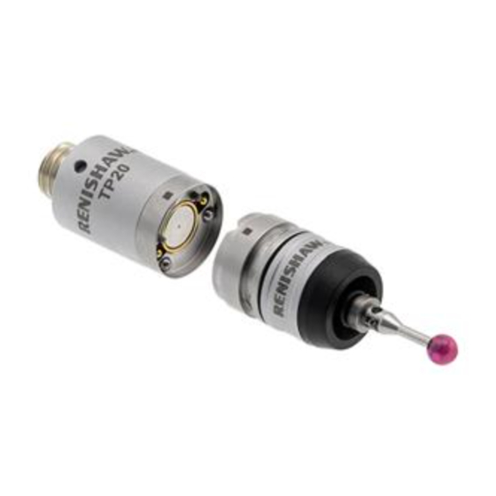
TP20. Neglecting to do so may result in failure of the probe to trigger. 1. The inhibit TP20 may not be armed at a distance of up to 100 mm from the front of the MCR20 probe module change rack. - Page 7 MSR1 module storage rack (manual operation) The Renishaw TP20 touch-trigger probe is a 5-way or 6-way kinematic probe with the facility to change stylus configurations without the need for re-qualification. A direct replacement for the industry-proven Renishaw TP2, the TP20 can be easily retrofitted into existing TP2 applications to bring this additional facility to both manual and DCC co-ordinate measuring machines (CMMs).
- Page 8 One or two TP20 probe modules (see TP20 probe kits for available combinations) Probe and stylus tools TP20 probe body The probe body incorporates a standard Renishaw M8 × 1.25 mm screw connector mount and is designed to house the mating half of the probe module's kinematic coupling. TP20 inhibit probe body This contains the magnetic proximity switch necessary to inhibit triggering of the probe during automatic changing of the probe modules.
- Page 9 TP20 user's guide www.renishaw.com Issued 06 2022...
-
Page 10: Trigger Force Options
Each probe module, which houses the kinematic switching touch sensor mechanism, carries the stylus assembly and provides overtravel in the X, Y and +Z axes ﴾–Z is offered when using the TP20 6‐way probe module﴿. Incorporating an M2 stylus mounting, each probe module is compatible with Renishaw's comprehensive range of M2 styli. - Page 11 TP20 user's guide www.renishaw.com TP20 probe kits The following TP20 probe kits are available from your supplier: Inhibit probe body Non-inhibit probe LF probe module MF probe module SF probe module EF probe module body A-1371-0290 A-1371-0640 A-1371-0291 A-1371-0641 A-1371-0292...
- Page 12 TP20 user's guide www.renishaw.com The following TP20 probe module kits are available from your supplier: TP20 probe module kit (probe module only) Part number Low force probe module A-1371-0392 Standard force probe module A-1371-0270 Medium force probe module A-1371-0271 Extended force probe module...
- Page 13 When using the rack, the inhibit version of the TP20 probe must be used. By generating a magnetic field about the front of each docking port lid, the MCR20 effectively ‘closes' the probe's inhibit switch during a probe module changing cycle. Rack function is completely passive and no electrical input is required.
- Page 14 TP20 user's guide www.renishaw.com MCR20 probe module changing rack kits are available with the following combinations of probe modules and may be ordered from your supplier: MCR20 kit part number LF probe module SF probe module MF probe module EF probe module...
- Page 15 Based on the industry standard range of MCR20 rack systems, TCR20 securely stores modules for rapid automatic changing, protecting mating surfaces from any airborne contaminants within the working envelope of the machine. TCR20 carries the full range of TP20 modules which are compatible with the PH20 system and can accommodate up to six module / stylus combinations.
- Page 16 TP20 user's guide www.renishaw.com MSR1 module storage rack kit The optional MSR1 module storage rack kit is not supplied with any TP20 probe modules. It is available in two different mounting options (please refer to the installation section for details).
-
Page 17: Component Connection
M2 stylus mount of the probe module and hand-tighten to secure. 2. Using the type S7 stylus tools provided, or type S20 spanner if fitting a stylus from the Renishaw GF range, fully hand-tighten the stylus into the stylus mount to achieve the recommended tightening torque of between 0.05 Nm and 0.15 Nm (maximum permissible torque is... - Page 18 TP20 user's guide www.renishaw.com Fitting a probe module and stylus onto a probe body 1. Visually examine the mating faces of both the probe module and the probe head for cleanliness. Where necessary, clean the mating surfaces using the CK200 cleaning kit (supplied).
- Page 19 Using the 1.5 mm hexagonal key supplied, fully hand-tighten the M3 cone point grubscrew (0.5 Nm - 1 Nm) to lock the MCR20 in position. NOTES: Whilst the TP20 system does not require that the MCR20 is aligned with the CMM axes, ease of programming or software constraints may make alignment with the CMM axes desirable.
- Page 20 Datuming MCR20 NOTES: Renishaw recommends that datuming of the MCR20 is performed using the Renishaw PS2R stylus supplied. If a different stylus is to be used, the length (L) must be either 20 mm or 30 mm and the appropriate ball radius (R) must be used to calculate offsets.
- Page 21 TP20 user's guide www.renishaw.com Establishing the docking centre for port 1 To establish the docking centre for port 1 (X1), carry out the following procedure: NOTE: The stylus shank may be used to take points P6 and P7. 1. Take points P6 and P7.
- Page 22 TP20 user's guide www.renishaw.com Establishing the docking centre for ports 2 to 6 To establish the docking centre for ports 2 (X2) to 6 (X6), perform the following calculations: Docking centre port 2 (X2) = X1 + 30 mm Docking centre port 3 (X3) = X2 + 30 mm...
-
Page 23: Tcr20 Alignment And Change Routine
TP20 user's guide www.renishaw.com Mounting TCR20 onto the CMM NOTE: To minimise the machine volume lost it is recommended that the TCR20 is mounted as close as possible to the extreme edge of the CMM's operating envelope. 1. Fix the rack base to the CMM bed using the appropriate fixing screw. Depending upon the size of screw required it may be necessary to also use a washer. - Page 24 TP20 user's guide www.renishaw.com Mounting MSR1 onto the CMM CAUTION: The MSR1 rack is not crash-protected. It is recommended that the rack is mounted outside or close to the edge of the working volume of the CMM. Two mounting options are available for the MSR1 - CMM table mounted and wall mounted.
- Page 25 TP20 user's guide www.renishaw.com Mounting MSR1 onto a wall To mount MSR1 onto a wall, carry out the following procedure: 1. Fix the wall mounting bracket (supplied) in the desired location using the holes or other secure means. 2. Locate the rack on the bracket and secure by engaging the M10 bolt (supplied) a few turns into the M10 nut located in the underside of the rack extrusion.
-
Page 26: Product Operation
Storing and changing probe modules NOTES: The inhibit switch in the inhibit version of the TP20 body will be automatically actuated by the magnetic field when it approaches the front of the MCR20 probe module changing rack. The minimum distance from the MCR20 probe module changing rack at which the TP20 is armed will vary with height. - Page 27 TP20 user's guide www.renishaw.com Storing a probe module To store a probe module, carry out the following procedure: Step 1.- Move to the safe clearance position Xn, Ys, Z for the vacant port (n). Step 2.- Move to the docking target co-ordinate for port (n) along the Y-axis at the docking height (Z).
- Page 28 TP20 user's guide www.renishaw.com Picking up a stored probe module To pick up a stored probe module, carry out the following procedure: Step 1.- Move along the X-axis in the direction necessary to arrive at the RP co-ordinates for the next port required.
- Page 29 Using the MSR1 module storage rack The location points for the TP20 probe modules are positioned approximately below the numbered labels on the rack. Accurate positioning is not necessary, as the magnetic force will pull them into the correct position.
-
Page 30: Technical Data
TP20 user's guide www.renishaw.com Technical data Measuring performance NOTE: The following data is derived from high accuracy test rig measurements and may not represent the performance achievable on a CMM. Please consult your CMM supplier for overall system accuracy information. - Page 31 TP20 user's guide www.renishaw.com Probing forces and overtravel limits Probe module XY (Trigger Z (Trigger force XY (Overtravel +Z (Overtravel XY** (Overtravel +Z (Overtravel type and stylus force (nominal (nominal at force (max. at force (max. at displacement) displacement) length...
-
Page 32: Technical Specifications
The TP20 is suitable for use with all Renishaw probe interfaces and probe heads which service the TP1, TP2 and TP6 touch-trigger probes. The TP20 is compatible with the PEL, PK, PAA and PEM series of probe extensions / adaptors. Diameter 13.2 mm... - Page 33 TP20 user's guide www.renishaw.com TCR20 Width 200 mm (7.87 in) Depth 57 mm (2.24 in) Base diameter 50 mm (1.97 in) Height to top of rack 186 mm (7.32 in) Height to bottom of ports 159 mm (6.26 in) Port entry velocity Maximum 800 mm/s (31.5 in/sec)
-
Page 34: Applications Guide
The mass of the stylus assembly and its centre of gravity - it is always best to use the shortest stylus possible The orientation of the probe body The levels of acceleration and vibration to which the TP20 probe will be subjected - these will vary with each type of CMM and movement velocity The following probe modules are available for use with the TP20 probe. -
Page 35: Recommended Stylus Limits
Minimise the mass of styli by using either ceramic or graphite fibre (GF) stems Recommended stylus limits Owing to the modular construction of the TP20 probe, it is recommended that the limits shown in the figures below are applied when selecting styli to be used. - Page 36 The standard force probe modules (SF, EM1 STD and EM2 STD) can be used with the following range of styli: Steel and carbide styli up to 40 mm long Renishaw graphite fibre (GF) type styli up to 50 mm long Star and cranked styli up to 20 mm offset...
- Page 37 TP20 user's guide www.renishaw.com 6-way probe module The recommended stylus limits for the 6-way probe module are: Any stylus type up to 30 mm long Star and cranked styli up to 10 mm offset Comparative stylus lengths A comparison of the minimum and maximum stylus lengths for use with each probe module is shown in the following figure:...
-
Page 38: Product Maintenance
Product maintenance NOTE: Maintenance of the TP20 probe is restricted to the periodic cleaning of the kinematic couplings of both the probe body and the probe module(s). To aid cleaning of these couplings, each TP20 probe is supplied with a Renishaw CK200 cleaning kit. - Page 39 Renishaw plc +44 (0)1453 524524 New Mills, Wotton-under-Edge +44 (0)1453 524901 Gloucestershire, GL12 8JR United Kingdom www.renishaw.com/cmmsupport For worldwide contact details, please visit our main website at www.renishaw.com/contact Issued 06 2022...
Need help?
Do you have a question about the TP20 and is the answer not in the manual?
Questions and answers