Table of Contents
Advertisement
Quick Links
Advertisement
Table of Contents

Related Manuals for Renishaw TS27R


Summary of Contents for Renishaw TS27R
- Page 1 Installation guide TS27R tool setting probe www.renishaw.com/ts27r #renishaw...
- Page 2 Compliance information for this product is available by scanning the QR code or visiting www.renishaw.com/mtpdoc...
-
Page 3: Table Of Contents
Recommended connection diagram for TS27R with HSI-C interface . . . . . . . . . . . . . . . . . - Page 4 Parts list . . . . . . . . . . . . . . . . . . . . . . . . . . . . . . . . . . . . . . . . . . . . . . . . . . . . . . . . . . . . . . . . . . . . . . . . . .5-1 TS27R tool setting probe...
-
Page 5: Before You Begin
Renishaw office. Renishaw warrants its equipment and software for a limited period (as set out in the Standard Terms and Conditions), provided that they are installed and used exactly as defined in associated Renishaw documentation. -
Page 6: Safety
Information to the equipment installer All Renishaw equipment is designed to comply with the relevant UK, EU and FCC regulatory requirements . It is the responsibility of the equipment installer to ensure that the following guidelines are adhered to, in order for the product to function in accordance with these regulations: •... -
Page 7: Product Basics
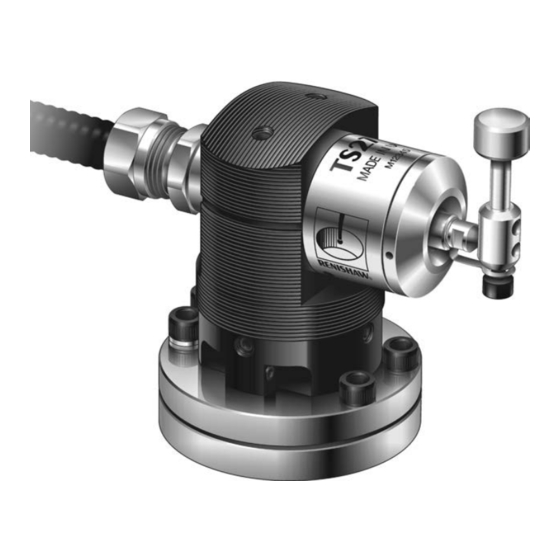
6 . Probe base holding screws Introduction The TS27R probe is used for tool setting on CNC machining centres . For tool length measurements and broken tool detection, the tool is driven against the probe’s stylus in the Z axis . Rotating tools can be set in the X and Y axes for tool radius offsets . -
Page 8: Achievable Set-Up Tolerances
Software routines Software routines for tool setting are available from Renishaw for various machine controllers and are described in the Probe software for machine tools – programs and features data sheet (Renishaw part no . H-2000-2298) . TS27R tool setting probe: Product basics... -
Page 9: Specification
. Trigger force is measured with a 50 mm (1 .97 in) stylus . These are the factory settings; manual adjustment is not possible . NOTE: For stylus recommendations, refer to the Styli and accessories technical specification (Renishaw part no . H-1000-3200) . - Page 10 This page is intentionally left blank . TS27R tool setting probe: Product basics...
-
Page 11: System Installation
Detach the probe base and the plinth from the probe by removing the two screws H and the screw L1 using a 4 mm A/F hexagon key . Fit the T bolt (not supplied by Renishaw) . Tighten the T bolt to secure the probe base to the machine table . -
Page 12: Cable
The TS27R conduit adaptor accepts Ø11 mm (0.43 in) flexible conduit. NOTE: The cable screen is connected to the machine via a 100 nF capacitor inside the TS27R to prevent possible earth loops . Ensure the cable screen is connected to the appropriate input on the interface . The interface units are fully described in the following publications: MI 8-4 interface unit installation and user’s... -
Page 13: Interfaces
SSR (solid-state relay) which can be connected as normally open (NO) or normally closed (NC) . Maximum current 50 mA peak Maximum voltage ±50 V peak An inhibit function is included, and a facility to drive an external probe status LED . www.renishaw.com/ts27r... -
Page 14: Recommended Connection Diagram For Ts27R With Hsi-C Interface
Recommended connection diagram for TS27R with HSI-C interface HSI-C interface NOTE: When Machine tool Probe connector (5-way) connecting the TS27R TS27R tool 19 . probe to the HSI-C setter 18 . interface, use the Blue Block 4 TS27R 17 . Screen... -
Page 15: Recommended Connection Diagram For Ts27R With Hsi Interface
Recommended connection diagram for TS27R with HSI interface HSI interface NOTE: When connecting Machine tool the TS27R probe to Standard connector (3-way) the HSI interface, use TS27R tool setter the connection labelled Blue 1 Probe Input + STANDARD PROBE . -
Page 16: Recommended Connection Diagram For Mi 8-4 Interface With Cnc Controller
A9 input resistors common interface 0 Vdc B1 +Vdc Power input B2 0 Vdc Yellow/green B3 screen Yellow/green Controller protective earth** ** Can also be referred to as ‘PE starpoint’ or ‘earthplate’ Controller protective ground TS27R tool setting probe: System installation... - Page 17 Recommended connection diagram for TS27R with MI 8-4 interface Machine tool Screen TS27R tool setter Blue Probe + Probe input TS27R probe Probe − For information regarding these connections, see the MI 8-4 100 nF interface unit installation and capacitor* user’s guide (Renishaw part no .
-
Page 18: Fitting The Stylus And Captive Link
The captive link connected to the probe and stylus holds onto the stylus, otherwise the stylus could fall into the machine and become lost . When a new captive link is fitted, it must be bent to accept screw C. See page 3-9, “Break stem”, for further information . TS27R tool setting probe: System installation... -
Page 19: Break Stem
Remove the broken parts and rebuild in the sequence shown above . NOTE: Earlier versions of the TS27R were supplied with cup-pointed grubscrews and a different break stem. Only fit current components supplied with this probe or with the break stem retrofit kit. -
Page 20: Stylus Level Setting
Side to side level is obtained by alternately adjusting grubscrews L3 and L4, which causes the probe module to rotate and change the stylus level setting . When a level stylus surface is obtained, tighten screws L3 and L4 . 3-10 TS27R tool setting probe: System installation... -
Page 21: Square Stylus Alignment
Fine rotational adjustment is obtained by loosening the four grubscrews R1 and alternately adjusting the two probe rotational adjuster screws R2 and R3 until the required tip parallelism to the axes is achieved . Retighten grubscrews R1, R2 and R3 . CAUTION: Ensure all screws are tight after adjustment . www.renishaw.com/ts27r 3-11... - Page 22 This page is intentionally left blank . 3-12 TS27R tool setting probe: System installation...
-
Page 23: Service And Maintenance
Service You may undertake the maintenance routines described in this handbook . Further dismantling and repair of Renishaw equipment is a highly specialised operation, which must be carried out at authorised Renishaw service centres . Equipment requiring repair, overhaul or attention under warranty should be returned to your supplier . -
Page 24: Diaphragm Maintenance
Refit the spring and metal eyelid (the spring’s widest diameter is against the metal eyelid). Refit the remaining components. See page 3-8, “Fitting the stylus and captive link” and page 3-9, “Break stem”, for further information . TS27R tool setting probe: Service and maintenance... -
Page 25: Parts List
Part number Description TS27R (disc) with MI 8-4 A-2008-0397 TS27R holder, probe module, break stem (× 2), disc stylus Ø12 .7 mm (Ø0 .5 in) and MI 8-4 interface . TS27R (square) with MI 8-4 A-2008-0396 TS27R holder, probe module, break stem (× 2), square tip stylus 19 .05 mm (0 .75 in) and MI 8-4... - Page 26 Type Part number Description Publications. These can be downloaded from our website at www.renishaw.com . MI 8-4 H-2000-5008 Installation guide: for the set up of MI 8-4 . H-5500-8554 Installation guide: for the set up of HSI . HSI-C H-6527-8501 Installation guide: for the set up of HSI-C .
- Page 27 This page is intentionally left blank . www.renishaw.com/ts27r...
- Page 28 © 1995–2022 Renishaw plc . All rights reserved . This document may not be copied or reproduced in whole or in part, or transferred to any other media or language by any means, without the prior written permission of Renishaw .
Need help?
Do you have a question about the TS27R and is the answer not in the manual?
Questions and answers