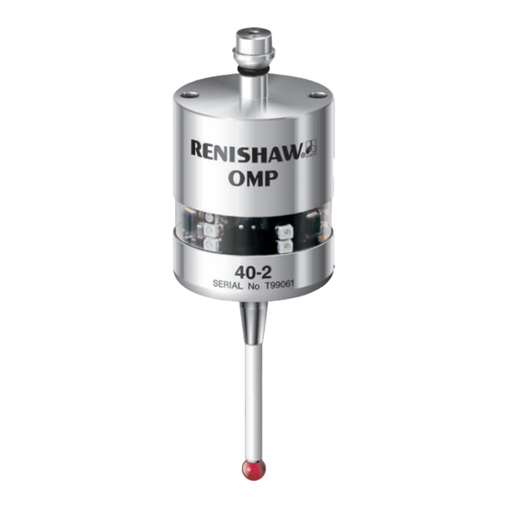
Renishaw OMP40-2 Installation Manual
Optical machine probe
Hide thumbs
Also See for OMP40-2:
- Quick start manual (178 pages) ,
- Manual (54 pages) ,
- Installation manual (48 pages)
Table of Contents
Advertisement
Advertisement
Table of Contents

Related Manuals for Renishaw OMP40-2


Summary of Contents for Renishaw OMP40-2
- Page 1 Installation guide H-4071-8504-03-A OMP40-2 optical machine probe...
- Page 2 © 2009 Renishaw plc. All rights reserved. This document may not be copied or reproduced in whole or in part, or transferred to any other media or language, by any means, without the prior written permission of Renishaw plc. The publication of material within this document does not imply freedom from the patent rights of Renishaw plc.
-
Page 3: Table Of Contents
Introduction ........................2.1 Optical transmission method ................... 2.1 Trigger Logic™ ........................ 2.2 Modes of operation ......................2.3 Configurable settings ....................... 2.4 OMP40-2 dimensions ...................... 2.5 OMP40-2 specification ....................2.6 Principal application ....................2.6 Overall dimensions ..................... 2.6 Weight ........................2.6 Operating ........................ - Page 4 Installing the OMP40-2 with an OMI-2/OMI-2T/OMI-2H/OMI ........3.1 Performance envelope with an OMI-2/OMI-2T/OMI-2H ..........3.2 Performance envelope with an OMI ................3.3 Installing the OMP40-2 with an OMM and MI12 ............3.4 Performance envelope with an OMM ................. 3.5 Preparing the OMP40-2 for use ................. 3.6 Fitting the stylus ....................
-
Page 5: Before You Begin
INACCURACIES IN THIS DOCUMENT. manufacturer's instructions. Trademarks Care of the probe RENISHAW® and the probe emblem used in the Keep system components clean and treat the RENISHAW logo are registered trademarks of probe as a precision tool. Renishaw plc in the UK and other countries. -
Page 6: Patents
OMP40-2 installation guide Patents Features of the OMP40-2 probe, and other similar Renishaw probes, are the subject of one or more of the following patents and/or patent applications: 0390342 2945709 2994401 0695926 0974208 3967592 1130557 2003-526170 2004-522961 1185838 1373995 2004-530234... -
Page 7: Ec Declaration Of Conformity
FCC Section 15.19 EC DECLARATION OF This device complies with Part 15 of the CONFORMITY FCC rules. Operation is subject to the following two Renishaw plc declares that the product:- conditions: Name OMP40-2 1. This device may not cause harmful Description Optical machine probe interference. -
Page 8: Safety
MUST be installed in a position strips are located securely. away from any potential sources of electrical noise, i.e. power transformers, servo drives The OMP40-2 has a glass window, handle with etc; care if broken, to avoid injury. •... -
Page 9: Omp40-2 Basics
Certain forms of light interference can cause false triggers or mimic a start signal and falsely The OMP40-2 is ideal for small to medium activate the probe. These effects are much machining centres including the growing range of reduced when modulated transmission is HSK machines. -
Page 10: Trigger Logic
OMP40-2 installation guide Trigger Logic™ All OMP40-2 settings are configured using the Trigger Logic™ technique. Trigger Logic™ (see Section 4 - Trigger Logic™) is a method that allows the user to view and select all available mode settings in order to customise a probe to suit a specific application. -
Page 11: Modes Of Operation
Note: This method is required when operating a twin probe system with an OMI-2T. After being switched on, the OMP40-2 must be on for 1 second minimum before being switched off. Timer off (time out) Time out will occur (12, 33 or 134 seconds) after the last probe trigger or reseat. -
Page 12: Configurable Settings
The OMP40-2 is factory set to standard Optical is introduced to the probe output. power. The OMP40-2 is factory set to trigger filter off. NOTE: It may be necessary to reduce the probe approach speed to allow for the increased stylus overtravel during the extended time delay. -
Page 13: Omp40-2 Dimensions
OMP40-2 dimensions 50 (1.97) 19 (0.75) Ø40 (Ø1.57) Battery cassette M4 stylus 12.5° 12.5 ° Probe status LEDs 50 (1.97) dimension given in mm (in) Stylus overtravel limits Stylus length ±X/±Y 50 (1.97) 12 (0.47) 6 (0.24) 100 (3.94) 22 (0.87) 6 (0.24) -
Page 14: Omp40-2 Specification
OMP40-2 installation guide OMP40-2 specification Principal application: Workpiece measurement and job set-up on small to medium machining centres Overall dimensions: Length 50 mm (1.97 in) Diameter 40 mm (1.57 in) Weight: with batteries without batteries 260 g (9.17 oz) 240 g (8.46 oz) -
Page 15: Batteries
OMP40-2 specification Batteries: Battery type: ½ AA Lithium Thionyl Chloride (3.6 V) x 2 Battery reserve life: Approximately 1 week after a low battery warning is first given Low battery indication: Blue flashing LED in conjunction with normal red or green probe status LED... - Page 16 OMP40-2 installation guide This page left intentionally blank...
-
Page 17: System Installation
PSU3 user's guide H-2000-5057 Probe and optical receiver The probe and receiver must be in the other's Coolant residue accumulating on the OMP40-2 field of view, and within the performance or OMI-2T/OMI-2/OMI-2H/OMI windows may envelope shown (pages 3.2/3.3). The OMP40-2 reduce the signal transmission range. -
Page 18: Performance Envelope With An Omi-2/Omi-2T/Omi-2H
OMP40-2 installation guide Performance envelope with an OMI-2/OMI-2T/OMI-2H (modulated transmission) Typical plot at 20 °C (68 °F) 360° transmission around probe axis in metres (feet) 75° 75° 60° 60° 45° 45° 30° 30° OMI-2/ OMP40-2 OMI-2T/ OMI-2H 15° 15° 0°... -
Page 19: Performance Envelope With An Omi
OMI (legacy transmission) Typical plot at 20 °C (68 °F) 360° transmission around probe axis in metres (feet) 75° 75° 60° 60° 45° 45° 30° 30° OMP40-2 15° 15° 0° 0° Optical 1 (3.3) centre line 1 (3.3) 15° 15° 2 (6.5) 2 (6.5) -
Page 20: Installing The Omp40-2 With An Omm And Mi12
50 °C to 60 °C (32 °F to 41 °F or 122 °F to shown (page 3.5). The OMP40-2 performance 140 °F) will result in some reduction in range. envelope is based on the receiver being at 0°, On large machine tools, it is possible to provide and vice-versa. -
Page 21: Performance Envelope With An Omm
Performance envelope with an OMM (legacy transmission) Typical plot at 20 °C (68 °F) 360° transmission around 75° probe axis in metres (feet) 75° 60° 60° 45° 45° OMP40-2 30° 30° 15° 15° 0° 0° Optical 1 (3.3) 1 (3.3) centre line 15°... -
Page 22: Preparing The Omp40-2 For Use
OMP40-2 installation guide Preparing the OMP40-2 for use Fitting the stylus M-5000-3707... -
Page 23: Installing The Batteries
Installing the batteries NOTES: See Section 5 - Maintenance for list of suitable battery types. When inserting batteries, check that the battery polarity is correct. If dead batteries are inadvertently inserted into the probe then the LEDs will remain a constant red, see page 4.4. -
Page 24: Mounting The Probe On A Shank
OMP40-2 installation guide Mounting the probe on a shank 2 mm AF 0.5 Nm - 1.5 Nm (0.37 lbf.ft - 1.1 lbf.ft) (x 2) -
Page 25: Stylus On-Centre Adjustment
Stylus on-centre adjustment 2 mm AF 0.5 Nm - 1.5 Nm (0.37 lbf.ft - 1.1 lbf.ft) NOTES: (x 4) If a probe and shank assembly is dropped, it must be rechecked for correct on-centre adjustment. Do not hit or tap the probe to achieve on-centre adjustment. -
Page 26: Calibrating The Omp40-2
OMP40-2 installation guide • Calibrating the OMP40-2 calibrating either in a ring gauge or on a datum sphere; • Why calibrate a probe? calibrating the probe length. A spindle probe is just one component of the Calibrating in a bored hole or on a measurement system which communicates with the machine tool. -
Page 27: Trigger Logic
Trigger Logic™ Reviewing the current probe settings Key to the symbols > 5 s LED short flash LED check LED long flash Switch off method Optical off Short timeout Medium timeout Long timeout 12 s 33 s 134 s Enhanced trigger filter setting Trigger filter Trigger filter Optical transmission method/Probe identification... -
Page 28: Probe Settings Record Table
Enhanced trigger filter Trigger filter off setting Trigger filter on Optical transmission Legacy start filter off method Legacy start filter on Modulated probe 1 Modulated probe 2 Optical power setting Low optical power Standard optical power OMP40-2 serial no .......... -
Page 29: Changing The Probe Settings
Changing the probe settings Insert batteries or, if already installed, remove for flashes will be followed by a blue flash). Keep 5 seconds and replace. Following the LED check, the stylus deflected until the 'switch on method' immediately deflect the stylus and hold deflected setting is displayed, then release the stylus. -
Page 30: Operating Mode
OMP40-2 installation guide Operating mode LEDs LEDs flashing LEDs flashing flashing green Probe status LEDs LED colour Probe status Graphic hint Flashing green Probe seated in operating mode Flashing red Probe triggered in operating mode Flashing green and blue Probe seated in operating mode... -
Page 31: Maintenance
Renishaw Service Centres. Equipment requiring repair, overhaul or attention under warranty should be returned to your supplier. CAUTION: The OMP40-2 has a glass window, handle with care if broken to avoid injury... -
Page 32: Changing The Batteries
OMP40-2 installation guide Changing the batteries CAUTIONS: Do not leave exhausted batteries in probe. When changing batteries, do not allow coolant or debris to enter the battery compartment. When changing batteries, check that the battery polarity is correct. Take care to avoid damaging the battery cassette gasket. -
Page 33: Battery Types
Battery type ½ AA Lithium Thionyl Chloride (3.6 V) x 2 Ecocel: EB1426 Dubilier: SB-AA02 Saft: LS 14250C, Maxell: ER3S LS 14250 Sanyo: CR 14250SE Tadiran: SL-750 Tadiran: SL-350, SL-550 Xeno: XL-050F TL-4902 TL-5902, TL-2150, TL-5101 Varta: CR 1/2 AA... - Page 34 OMP40-2 installation guide This page left intentionally blank...
-
Page 35: Fault Finding
Optical/magnetic interference Check for interfering lights or motors Consider removing interfering source Transmission beam obstructed Check that OMP40-2 and receiver windows are clean, and remove any obstruction Probe out of range/not aligned Check alignment and if receiver with receiver fixing is secure... - Page 36 OMP40-2 installation guide Symptom Cause Action Machine stops Optical communication Check interface/receiver and unexpectedly during a obstructed remove obstruction probing cycle Interface/receiver/machine fault Refer to interface/receiver/ machine user’s guide Dead batteries Change batteries False probe trigger Enable enhanced trigger filter...
- Page 37 Symptom Cause Action Poor probe Debris on part or stylus Clean part and stylus repeatability and/or accuracy Poor tool change repeatability Re-datum probe after each tool change Loose probe mounting on shank or loose stylus Check and tighten as appropriate Excessive machine vibration Enable enhanced trigger filter Eliminate vibrations...
- Page 38 OMP40-2 installation guide Symptom Cause Action Probe fails to switch-off Wrong switch-off mode selected Reconfigure to optical off mode (where optical off is required) Optical/magnetic interference Check for interfering lights or motors Consider removing the interfering source Probe is inadvertently switched-...
-
Page 39: Parts List
Parts list Type Part number Descripion OMP40-2 A-4071-0001 OMP40-2 probe with batteries, tool kit and Quick-start guide. Optical on, set to: optical off/trigger filter off/legacy transmission, start filter off/standard power. OMP40-2 A-4071-0002 OMP40-2 probe with batteries, tool kit and Quick-start guide. - Page 40 A-2075-0142 MI12 interface unit. PSU3 A-2019-0018 PSU3 power supply unit 85-264 V input. Publications. These can be downloaded from our web site at www.renishaw.com OMP40-2 A-4071-8500 Quick-start guide for rapid set-up of the OMP40-2 probe, includes CD with OMP40-2 publications.
- Page 42 Renishaw plc +44 (0)1453 524524 +44 (0)1453 524901 New Mills, Wotton-under-Edge, uk@renishaw.com Gloucestershire, GL12 8JR United Kingdom www.renishaw.com For worldwide contact details, please visit our main website at www.renishaw.com/contact *H-4071-8504-03* © 2009 Renishaw plc Issued February 2009 Part no. H-4071-8504-03-A...
Need help?
Do you have a question about the OMP40-2 and is the answer not in the manual?
Questions and answers