
Subscribe to Our Youtube Channel
Related Manuals for Esu SwitchPilot 3 51830


Summary of Contents for Esu SwitchPilot 3 51830
- Page 1 SwitchPilot 3 Instruction manual 1 . E d i t i o n , J a n u a r y 2 0 2 1 From Decoder Firmware 3.0.9 51830 SwitchPilot 3 SWitch Pilot P/N 00221-24443...
-
Page 2: Table Of Contents
Content 1. Declaration of Conformity ........3 6.4. Configuring outputs ...........19 6.5. Setting fade-in and fade-out times ......20 2. WEEE-Erklärung ............4 6.6. Status information ............20 6.6.1. Display software version & track voltage ....20 3. Important Notes ............4 6.6.2. Displaying output states ...........20 6.6.3. -
Page 3: Declaration Of Conformity
Alle anderen Warenzeichen sind Eigentum ihrer jeweiligen Rechteinhaber. ESU electronic solutions ulm GmbH & Co. KG entwickelt entsprechend seiner Politik die Produkte ständig weiter. ESU behält sich deshalb das Recht vor, ohne vorherige Ankündigung an jedem der in der Dokumentation beschriebenen Produkte Änderungen und Verbesserungen vorzunehmen. -
Page 4: Weee-Erklärung
3. Important Notes Disposal of old electrical and electronic equipment (valid in the Congratulations on your purchase of an ESU SwitchPilot 3 deco- European Union and other European countries with separate coll- der. This manual wants to introduce you step by step to the possi- ection system). -
Page 5: Features
Features 4. Features 4.2. Technical Data SwitchPilot 3 ESU SwitchPilot 3 decoders are optimized for stationary use on your model train layout and can switch conventional solenoid Input voltage 12V - 20V DC power supply turnout drives, daylight signals, magnetic uncouplers, incande- 12V - 16V AC power supply scent lamps (bulbs) or other stationary electric loads. -
Page 6: Operating Modes
Operating modes 4.4. Operating modes pre-determined pulse time, the output will still be switched off. Limiting the switch-on time prevents accessories to blow. The SwitchPilot 3 has a total of 8 transistor outputs, which are grouped in 4 output pairs 1 to 4. Each output pair contains two Optionally, the output can also be slowly dimmed up and dimmed outputs (Out A and Out B) and can be configured individually to down (so-called „zoom”... -
Page 7: Operating Peco Turnout Drives
Operating modes 4.4.2. Operating PECO turnout drives 4.4.3. K83 operation (momentary action mode) The PECO mode corresponds to the afore mentioned pulse ope- In K83 mode, the output remains active until the button on the ration with the exception that to increase the peak current the command station or control panel is released. -
Page 8: K84 Operation (Bistable Continuous Operation)
Operating modes 4.4.4. K84 Operation (Bistable continuous operation) In K84 mode, the two outputs are alternately switched on and off: When pressing the first button (red) on the command station, the Output Out A is turned on. It remains active until pressing the assigned button (green) activates the output Out B of the same output group. -
Page 9: Alternate Flasher Mode
Operating modes 4.4.5. Alternate flasher mode 4.4.6. Operating mode switch In this mode, the outputs Out A and Out B of an output pair are With the decoder´s mode switch, you can quickly switch all output switched on alternately with an adjustable flashing frequency. The pairs simultaneously to the „k83”... -
Page 10: Connection To The Digital System
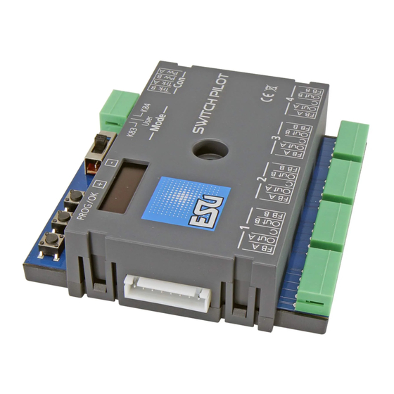
Connection to the digital system 5. Connection to the digital system We recommend that you first configure the SwitchPilot 3 decoder completely and then install it on the layout. 5.1. Terminals Fig. 5 shows the SwitchPilot 3 with all terminals. a) Turnouts, daylight signals, uncouplers and similar electric loads shall be connected to the terminals labelled 1 to 4 for the out- put pairs 1 to 4. -
Page 11: Power Supply By The Digital System
Trk A and Trk B. commend the use of a stabilized DC power supply with at least 18V DC at least 3A output power (e.g.: ESU part number 50119). If accessories (e.g.: Märklin® K track) do not switch at all or only respond with little power, check the track voltage and increase For switching Märklin®... -
Page 12: Wiring The Outputs
Wiring the outputs 5.4. Wiring the outputs Should the turnout not be aligned as you intended after pressing the respective button on your command station respectively con- 5.4.1. Solenoid turnout drives trol panel (diverging and straight route are reversed), please swap You may use any of the commercially available solenoid turnout the wires at terminals Out A and Out B. -
Page 13: Uncoupling Tracks
5.5. Wiring the feedback contacts shown in Figure 8, Output 3), a series resistor must be used to The SwitchPilot 3 can report the actual turnout status to the ESU limit the current. The resistance value depends to a large extent ECoS command station via RailCom®. -
Page 14: Connecting The Switchpilot Extension
Wiring the outputs 5.6. Connecting the SwitchPilot Extension b) Terminals for ground and „U+” (rectified track voltage, sup- plied by SwitchPilot 3) for powering DC turnout motors. The SwitchPilot Extension module is docked sideways to the SwitchPilot 3; press the extension module with the 8-pin plugs 5.6.2. -
Page 15: Lgb® Turnout Drive
Wiring the outputs 5.6.3. LGB® Turnout drive 5.6.4. Turnout frog polarization The wiring is as shown in Fig. 12. Unless reprogrammed, the mo- Mit dem SwitchPilot Exension Modul können sehr einfach Wei- tors are supplied with electricity for approx. 520 msec and are then chen-Herzstücke polarisiert werden. -
Page 16: Configuration With Oled
Configuration with OLED 6. Configuration with OLED Each SwitchPilot 3 can be assigned such a 4-series group: this is the so-called accessory address. The programming of accessory decoders was usually very cum- The accessory address is stored internally in CV 1 and CV 9. The bersome in the past. -
Page 17: Assigning Turnout Numbers
Assigning turnout numbers 6.1.1. Assigning turnout numbers Ex works, the 4 double outputs of the SwitchPilot 3 respond to turnout numbers 0001 to 0004. The turnout numbers can be ea- sily changed directly on the SwitchPilot 3. a) Check whether the display shows the screen saver (lettering „SP”... -
Page 18: Introduction To The Operating Structure
Introduction to the operating structure 6.2. Introduction to the operating structure a) Name of the panel b) Name of setting option 1 The configuration with the aid of the OLED display and the 3-but- c) Value of the setting option 1 ton input unit enables you to set all parameters of the SwitchPilot d) Name of setting option 2 3 decoder. -
Page 19: Address Mode For Roco® Command Stations
Introduction to the operating structure • If you want to change a setting option of the currently selected 6.4. Configuring outputs panel, press the PROG/OK button once. The setting option 1 of Each output can be configured individually. For this purpose, the the screen will now flash as a sign that it can be changed. -
Page 20: Setting Fade-In And Fade-Out Times
Configuration For particularly realistic fade-in and fade-out effects, you can add If the SwitchPilot 3 is powered directly by the command station, a „zoom” function to each output, if so desired „Voltage” displays the digital track voltage, otherwise the voltage of the connected power supply. -
Page 21: Viewing Feedback Input States
Configuration 7. Configuration with LokProgrammer 6.6.3. Viewing feedback input states The “Screen Feedback State” is suitable for checking whether the Please always use the latest PC software for your LokProgrammer, feedback wiring has been connected correctly (see chapter 5.5) but at least version 5.1.0. To ensure a correct reading, connect the SwitchPilot 3 as shown in Fig. -
Page 22: Configuration Pom (Programming On The Main)
Configuration POM 8. Configuration POM (Programming on the Main) You can write all the CVs of the SwitchPilot 3 decoder and read them subject to the capabilities of the command station. With the The SwitchPilot 3 may remain installed on your layout during pro- ECoS, this is done as follows: gramming. -
Page 23: Configuration With The Programming Track
Configuration with the programming tack 9. Configuration with the programming track The decoder is now ready to „learn” an address as soon as an accessory of the desired group of 4 is switched on at the com- In some cases, it may be desirable to change the properties of the mand station. -
Page 24: Railcom
RailCom 11. RailCom® 11.2. Turnout status feedback with the ECoS The ESU ECoS can display the current turnout status and immedi- RailCom® is a technique for transferring information from the de- ately display deviations (e.g.: jammed turnouts or defective drives). -
Page 25: Reset To Factory Default (Decoder Reset)
Decoder reset 12. Reset to factory default (decoder reset) • Now go to the interlocking (turnout control panel). If the current status does not match the desired status, this will be indicated by a small exclamation point. You can restore the decoder‘s factory default settings at any time. Depending on the design of the feedback device, the feedback li- 12.1. -
Page 26: Support
10.00 to 12.00 o‘ clock by Fax : +49 (0) 731 - 1 84 78 - 299 by E-Mail: www.esu.eu/kontakt by mail: ESU GmbH & Co. KG Edisonallee 29 D-89231 Neu-Ulm www.esu.eu For USA, Canada, Australia by phone: +1 570-980-1982 Tuesday &... - Page 27 Menu reference SwitchPilot 3 Options Screen ADDRESS Switch 1-4: Turnout numbers outputs 1 to 4 Switch 1-4: 0001-0004 ADDRESS MODE Mode: RCN-213: Addressing as RCN-213. Mode : RCN-213 Mode: ROCO : Addressing as ROCO. OUTPUT MODE 1 Mode: IMPULSE | PECO | K83 | K84 |AltFlash Mode : Impulse Time: 130 ms | 195 ms | ..
- Page 28 Menu reference SwitchPilot 3 INFORMATION HW: Hardware version of the decoder. : 3.0 SW: Software version of the decoder. Update with LokProgrammer : 3.0.9 Voltage: Supply voltage of the decoder (if necessary rail tension) Voltage : 18.4V FEEDBACK STATE 1 2 3 4 .».»..».
-
Page 30: Solenoid Address & Turnout Numbers
Solenoid address & turnout numbers 16. Solenoid address & turnout numbers Turnout numbers Address CV1 CV 9 CV1 and CV9 follow RCN-213 Turnout numbers Address CV1 CV 9... - Page 31 Solenoid address & turnout numbers Turnout numbers Address CV1 CV 9 Turnout numbers Address CV1 CV 9...
-
Page 32: List Of All Supported Cvs
Version number Internal software version of the decoder. Manufacturer ID Manufacturer number (ID) of ESU. Writing the value 8 resets all CV to the factory setting. Decoder address 1, Upper 3 bits (bits 6 - 8) of the first decoder address for outputs 1 to 4. - Page 33 List of all supported CVs Name Description Range Value RailCom Activation and configuration of the RailCom function Configuration Description Value Data transmission on channel 2 No data transmission on channel 2 Data transmission allowed on channel 2 Configuration DCC configuration settings for the SwitchPilot 128,136 register Description...
-
Page 34: Change History
Change history 18. Change history 1. E 2020 dition EcEmbEr • Initial Document... -
Page 35: Warranty Certificate
Therefore ESU electronic solutions ulm GmbH & Co. KG grants you a warranty for the purchase of ESU products that far exceeds the national warranty as governed by legislation in your country and beyond the warranty from your authorised ESU dealer. - Page 36 Trouble shooting sheet 1. Personal data (Please write in BLOCK LETTERS) Name: ....Street: ....ZIP/City: ....| | | | | | Country: ....Email: ....Phone: ....Date: ..... Signature: ..... 2. Error Transistor outputs Short circuit Servo outputs No function from the start No Function Programming on the Main...
Need help?
Do you have a question about the SwitchPilot 3 51830 and is the answer not in the manual?
Questions and answers