
Related Manuals for Unitron System 274


Summary of Contents for Unitron System 274
- Page 1 System 274 ZOOM STEREO MICROSCOPE MANUAL 73 Mall Drive, Commack, NY 11725 • 631-543-2000 (P) • 631-589-6975 (F) www.unitronusa.com • info@unitronusa.com...
-
Page 2: Table Of Contents
SYSTEM 274 STEREO MICROSCOPES CONTENTS SAFETY NOTES ........................3 CARE AND MAINTENANCE ....................3 INTRODUCTION ........................4 UNPACKING AND COMPONENTS ..................4 COMPONENT DIAGRAMS ....................5-7 ASSEMBLY .......................... 8 ADJUSTMENT AND OPERATION ADJUSTING BINOCULAR VIEWING HEAD ..............15 FOCUS ADJUSTMENT ....................16 SPECIFICATIONS ...................... -
Page 3: Safety Notes
A regular schedule of preventative maintenance by qualified service personnel is highly recommended. Your authorized UNITRON ® distributor can arrange for this service. -
Page 4: Introduction
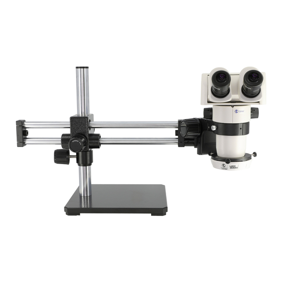
SYSTEM 274 STEREO MICROSCOPES INTRODUCTION Congratulations on the purchase of your new UNITRON ® microscope. UNITRON ® microscopes are engineered and manufactured to the highest quality standards. Your microscope will last a lifetime if used and maintained properly. UNITRON ®... - Page 5 SYSTEM 274 STEREO MICROSCOPES Ergonomic Binocular Head Eyepieces Zoom Body Auxiliary Lens/Objective Articulating Focus Knob Arm with Focus Mount Vertical Drop Post Extension Vertical Post Bench Clamp UNITRON ® 73 Mall Drive, Commack, NY 11725 • 631-543-2000 • www.unitronusa.com...
-
Page 6: Assembly
SYSTEM 274 STEREO MICROSCOPES ASSEMBLY The following photos show how to assemble the various modules in the order of assembly. When assembling the microscope, make sure that all parts are free of dust and dirt, and avoid scratching any parts or touching glass surfaces. - Page 7 SYSTEM 274 STEREO MICROSCOPES 3. Place the base on the table and unscrew the cap on the vertical post. 4. Insert the safety lock collar onto the vertical post and tighten/lock it using the clamp. 5. Slide the horizontal pillar with cross block into the vertical post.
- Page 8 SYSTEM 274 STEREO MICROSCOPES 7. Replace the cap back onto the vertical post. 8. Screw the lock lever on the end of the horizontal pillar. This lock lever secures the e-arm or focus mount. 9. Insert the e-arm or focus mount into the end of the horizontal bar and tighten using the lock lever.
- Page 9 SYSTEM 274 STEREO MICROSCOPES 11. E-arm or focus mount can be inserted from the TOP, BOTTOM or HORIZONTALLY of the horizontal bar. Set e-arm or focus mount up at various angles and tighten the lock lever for oblique viewing. Ball Bearing Boom Stand assembly is complete.
- Page 10 SYSTEM 274 STEREO MICROSCOPES Assembling the Articulating Arm with Vertical Extension Refer to the diagram below for all parts and the location of those parts during assembly. UNITRON ® 73 Mall Drive, Commack, NY 11725 • 631-543-2000 • www.unitronusa.com...
- Page 11 SYSTEM 274 STEREO MICROSCOPES 1. Attach stand clamp to work surface. 2. Attach safety collar to vertical post. Secure with knob screw. 3. Attach moveable arm to vertical post above safety collar. Secure to vertical post with knob screw (left). Attach second knob screw (right), but do not tighten.
- Page 12 SYSTEM 274 STEREO MICROSCOPES 4. Attach second moveable arm to first moveable arm. Be sure to insert nylon washer over the pin of the second moveable arm and the receiving hole of the first moveable arm. The washer should be between the arms to allow articulation (refer to the parts diagram).
- Page 13 SYSTEM 274 STEREO MICROSCOPES 7. Insert drop post into 3 moveable arm and secure with knob screw. 8. Slide focus mount onto drop post and secure with knob screw on the back of the focus mount. 9. Secure the focus mount to the drop post by threading the metal safety thumb screw into the bottom of the drop post.
- Page 14 SYSTEM 274 STEREO MICROSCOPES Mounting the Zoom Body 1. Carefully place the zoom body into the focus mount and tighten the lock screw to secure the zoom body in place. 2. Use caution not to over tighten the locking screw as this may cause damage to the instrument.
-
Page 15: Adjustment And Operation
SYSTEM 274 STEREO MICROSCOPES Installing the Eyepieces 1. Remove the dust caps from the eyepiece tubes. 2. Insert the eyepieces into the eyepiece tube. Be sure to install the eyepieces all the way into the tube. 3. Set the eyepiece diopter scale for each eyepiece to 0. -
Page 16: Focus Adjustment
SYSTEM 274 STEREO MICROSCOPES Focus Adjustment Adjusting the Rotation Tension of the Focus Adjustment Knob (Fig. 8, Fig. 9) To adjust tension, hold both left and right focus adjustment knobs ① with both hands, hold the left knob (to prevent it from turning), and rotate the... -
Page 17: Specifications
SYSTEM 274 STEREO MICROSCOPES SPECIFICATIONS System 274 6.3:1 Parallel Zoom Body EYEPIECE Objective Working WF 10X (Ø24mm) Lens Distance Total Visual Field (mm) Magnification (mm) 0.5X 4X-25X 60-9.6 TROUBLESHOOTING Under certain conditions, performance of this unit may be adversely affected by factors other than defects. -
Page 18: Maintenance
UNITRON® distributor or UNITRON® at (631) 543-2000. This warranty is limited to the continental United States of America. All items returned for warranty repair must be sent freight prepaid and insured to Unitron Ltd., 73 Mall Drive, Commack, NY 11725 – USA. All warranty repairs will be returned freight prepaid to any destination within the continental United States of America.
Need help?
Do you have a question about the System 274 and is the answer not in the manual?
Questions and answers