KROHNE OPTISWITCH 3200 C Handbook
Vibrating level switch, transistor (npn/pnp)
Hide thumbs
Also See for OPTISWITCH 3200 C:
- Operating instructions manual (36 pages) ,
- Handbook (36 pages) ,
- Technical data sheet (19 pages)
Table of Contents
Advertisement
Quick Links
Advertisement
Table of Contents

Related Manuals for KROHNE OPTISWITCH 3200 C


Summary of Contents for KROHNE OPTISWITCH 3200 C
- Page 1 OPTISWITCH 3200 C Handbook Vibrating Level Switch Transistor (NPN/PNP)
-
Page 2: Table Of Contents
Maintenance ........................22 Rectify faults ........................22 Exchanging the electronics module ................23 Instrument repair ......................24 Dismount Dismounting steps......................25 Disposal ......................... 25 Supplement Technical data ........................ 26 Dimensions ........................28 Trademark ........................30 OPTISWITCH 3200 C • Transistor (NPN/PNP) - Page 3 Contents Safety instructions for Ex areas Take note of the Ex specific safety instructions for Ex applications. These instructions are attached as documents to each instrument with Ex approval and are part of the operating instructions manual. Editing status: 2017-03-06 OPTISWITCH 3200 C • Transistor (NPN/PNP)
-
Page 4: About This Document
This arrow indicates a single action. Sequence of actions Numbers set in front indicate successive steps in a procedure. Battery disposal This symbol indicates special information about the disposal of bat- teries and accumulators. OPTISWITCH 3200 C • Transistor (NPN/PNP) -
Page 5: For Your Safety
During work on and with the device the required personal protective equipment must always be worn. Appropriate use The OPTISWITCH 3200 C is a sensor for point level detection. You can find detailed information about the area of application in chapter "Product description". Operational reliability is ensured only if the instrument is properly used according to the specifications in the operating instructions manual as well as possible supplementary instructions. -
Page 6: Safety Label On The Instrument
EU conformity The device fulfils the legal requirements of the applicable EU guide- lines. By affixing the CE marking, we confirm successful testing of the product. SIL conformity OPTISWITCH 3200 C meets the requirements to the functional safety according to IEC 61508. Further information is available in the Safety Manual "OPTISWITCH 3XXX". Safety instructions for Ex areas Please note the Ex-specific safety information for installation and op- eration in Ex areas. These safety instructions are part of the operating instructions manual and come with the Ex-approved instruments. -
Page 7: Product Description
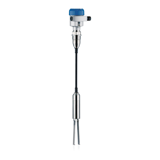
OPTISWITCH 3200 C point level switch • Documentation – This operating instructions manual – Ex specific safety instructions (with Ex versions), if necessary further certificates Constituent parts The OPTISWITCH 3200 C consists of the components: • Housing lid • Housing with electronics • Process fitting with tuning fork Fig. 1: OPTISWITCH 3200 C with plastic housing... -
Page 8: Principle Of Operation
3 Product description Principle of operation Application area OPTISWITCH 3200 C is a point level sensor with tuning fork for point level detection. It is designed for industrial use in all areas of process technology and is preferably used for bulk solids. -
Page 9: Storage And Transport
Protected against solar radiation • Avoiding mechanical shock and vibration • Storage and transport Storage and transport temperature see chapter "Supplement - temperature Technical data - Ambient conditions" • Relative humidity 20 … 85 % OPTISWITCH 3200 C • Transistor (NPN/PNP) -
Page 10: Mounting
(e.g. through cleaning processes) or on cooled or heated vessels. Fig. 2: Measures against moisture ingress Transport Do not hold OPTISWITCH 3200 C on the vibrating element. Espe- cially with flange and tube versions, the sensor can be damaged by the weight of the instrument. Remove the protective cover just before mounting... -
Page 11: Mounting Instructions
The tuning fork must be mounted in a way that takes the arrangement of the filling and emptying apertures into account. To compensate measurement errors caused by the material cone in cylindrical vessels, the sensor must be mounted at a distance of d/6 from the vessel wall. OPTISWITCH 3200 C • Transistor (NPN/PNP) - Page 12 4 Mounting Fig. 3: Filling and emptying centred Fig. 4: Filling in the centre, emptying laterally OPTISWITCH 3200 C Discharge opening Filling opening OPTISWITCH 3200 C • Transistor (NPN/PNP)
- Page 13 Inflowing medium If OPTISWITCH 3200 C is mounted in the filling stream, unwanted false measurement signals can be generated. For this reason, mount OPTISWITCH 3200 C at a position in the vessel where no disturbanc- es, e.g. from filling openings, agitators, etc., can occur. Fig. 5: Inflowing medium Product flow To make sure the tuning fork of OPTISWITCH 3200 C generates as little resistance as possible to product flow, mount the sensor so that the surfaces are parallel to the product movement.
- Page 14 Marking with screwed version 2 Direction of flow Baffle protection against In applications such as grit chambers or settling basins for coarse falling rocks sediments, the vibrating element must be protected against damage with a suitable baffle. This baffle must be manufactured by you. > 125 mm (> 5") Fig. 7: Baffle for protection against mechanical damage OPTISWITCH 3200 C • Transistor (NPN/PNP)
-
Page 15: Connecting To Power Supply
With Ex instruments, the housing cover may only be opened if there is no explosive atmosphere present. Proceed as follows: 1. Unscrew the housing lid 2. Loosen compression nut of the cable gland and remove blind plug OPTISWITCH 3200 C • Transistor (NPN/PNP) -
Page 16: Wiring Plan, Single Chamber Housing
10. If necessary, carry out a fresh adjustment 11. Screw the housing lid back on The electrical connection is finished. Wiring plan, single chamber housing The following illustrations apply to the non-Ex as well as to the Ex-d version. OPTISWITCH 3200 C • Transistor (NPN/PNP) - Page 17 Stainless steel (not with Ex d) Filter element for pressure compensation (not with Ex d) Wiring plan We recommend connecting OPTISWITCH 3200 C in such a way that the switching circuit is open when there is a level signal, line break or failure (safe state).
- Page 18 5 Connecting to power supply 1 2 3 4 Fig. 11: NPN action 1 2 3 4 Fig. 12: PNP action OPTISWITCH 3200 C • Transistor (NPN/PNP)
-
Page 19: Setup
(1) It is already preset and must only be modified in special cases. By default, the potentiometer of OPTISWITCH 3200 C is set to the right stop (> 0.02 g/cm³ or 0.0008 lbs/in³). In case of very light-weight solids, turn the potentiometer to the left stop (> 0.008 g/cm³ or... -
Page 20: Function Table
6 Setup 0.0003 lbs/in³). OPTISWITCH 3200 C will thus be more sensitive and can detect light-weight solids more reliably. For instruments detecting solids in water, these settings are not ap- plicable. The density range is preset and must not be changed. - Page 21 6 Setup Level Switching status Control lamp Fault open flashes red OPTISWITCH 3200 C • Transistor (NPN/PNP)
-
Page 22: Maintenance And Fault Rectification
Exchange the instrument or send it in for repair Reaction after fault recti- Depending on the reason for the fault and the measures taken, the fication steps described in chapter "Set up" may have to be carried out again. OPTISWITCH 3200 C • Transistor (NPN/PNP) -
Page 23: Exchanging The Electronics Module
9. Insert the electronics module carefully. Make sure that the plug is in the correct position. 10. Screw in and tighten the two holding screws with a screwdriver (Torx size T10 or Phillips 4) 11. Insert the wire ends into the open terminals according to the wir- ing plan OPTISWITCH 3200 C • Transistor (NPN/PNP) -
Page 24: Instrument Repair
By doing this you help us carry out the repair quickly and without hav- ing to call back for needed information. • Print and fill out one form per instrument • Clean the instrument and pack it damage-proof • Attach the completed form and possibly also a safety data sheet to the instrument OPTISWITCH 3200 C • Transistor (NPN/PNP) -
Page 25: Dismount
WEEE directive. Correct disposal avoids negative effects on humans and the environ- ment and ensures recycling of useful raw materials. Materials: see chapter "Technical data" If you have no way to dispose of the old instrument properly, please contact us concerning return and disposal. OPTISWITCH 3200 C • Transistor (NPN/PNP) -
Page 26: Supplement
Torque for NPT cable glands and Conduit tubes Ʋ Plastic housing max. 10 Nm (7.376 lbf ft) Ʋ Aluminium/Stainless steel housing max. 50 Nm (36.88 lbf ft) Output variable Output Floating transistor output, permanently shortcircuit-proof Load current < 400 mA OPTISWITCH 3200 C • Transistor (NPN/PNP) - Page 27 10 … 55 V DC Power consumption max. 0.5 W Electrical protective measures Protection rating IP 66/IP 67 (NEMA Type 4X) Depending on the version M12 x 1, according to ISO 4400, Harting, 7/8" FF. OPTISWITCH 3200 C • Transistor (NPN/PNP)
-
Page 28: Dimensions
ø 77mm (2.72") ø 84mm ø 77mm (3.03") (3.31") (3.03") M20x1,5/ M20x1,5/ M20x1,5/ M20x1,5 ½ NPT ½ NPT ½ NPT Fig. 25: Housing versions Plastic single chamber Stainless steel single chamber Aluminium - single chamber OPTISWITCH 3200 C • Transistor (NPN/PNP) - Page 29 9 Supplement G1½ ø 43 mm (1.69") ø 11 mm (0.43") ø 43 mm (1.69") Fig. 26: OPTISWITCH 3200 C, threaded version G1½ (DIN ISO 228/1) Sensor length, see chapter "Technical data" OPTISWITCH 3200 C • Transistor (NPN/PNP)
-
Page 30: Trademark
9 Supplement Trademark All the brands as well as trade and company names used are property of their lawful proprietor/ originator. OPTISWITCH 3200 C • Transistor (NPN/PNP) - Page 31 Notes OPTISWITCH 3200 C • Transistor (NPN/PNP)
- Page 32 Products and systems for the oil and gas industry KROHNE Messtechnick GmbH & Co. KG Ludwig-Krohne-Straße 5 D-47058 Duisburg Tel.: +49 (0) 203 301 0 Tel.: +49 (0) 203 301 10389 info@krohne.de The current list of all KROHNE contacts and addresses can be found at: www.krohne.com...
Need help?
Do you have a question about the OPTISWITCH 3200 C and is the answer not in the manual?
Questions and answers