KROHNE OPTISWITCH 3200 C Operating Instructions Manual
With relay output
Hide thumbs
Also See for OPTISWITCH 3200 C:
- Handbook (36 pages) ,
- Technical data sheet (19 pages) ,
- Handbook (32 pages)
Table of Contents
Advertisement
Quick Links
Advertisement
Table of Contents

Subscribe to Our Youtube Channel
Related Manuals for KROHNE OPTISWITCH 3200 C


Summary of Contents for KROHNE OPTISWITCH 3200 C
- Page 1 Operating Instructions OPTISWITCH 3200 C with relay output...
-
Page 2: Table Of Contents
Dismounting procedure ....Disposal ......OPTISWITCH 3200 C - with relay output... - Page 3 Dimensions ......Supplementary operating instructions manuals Information: OPTISWITCH 3200 C is available in different versions. Depending on the selected version, supplementary operating instructions manuals may also come with the shipment. The supplementary operating instructions manuals are listed in section "Product description.
-
Page 4: About This Document
This symbol indicates special instructions for Ex applications. List The dot set in front indicates a list with no implied sequence. à Action This arrow indicates a single action. Sequence Numbers set in front indicate successive steps in a procedure. OPTISWITCH 3200 C - with relay output... -
Page 5: For Your Safety
(e.g. the VDE regulations in Germany) as well as all prevailing safety regulations and accident prevention rules. 2.5 CE conformity OPTISWITCH 3200 C is in CE conformity with EMC (89/336/ EWG), fulfils NAMUR recommendation NE 21 and is in CE conformity with LVD (73/23/EWG). -
Page 6: Sil Conformity
For your safety 2.6 SIL conformity OPTISWITCH 3200 C fulfills the requirements of functional safety according to IEC 61508/IEC 61511. You can find further information in the supplementary instructions manual "Safety Manual - Functional safety (SIL) OPTISWITCH 3XXX". 2.7 Safety instructions for Ex areas Please note the Ex-specific safety information for installation... -
Page 7: Product Description
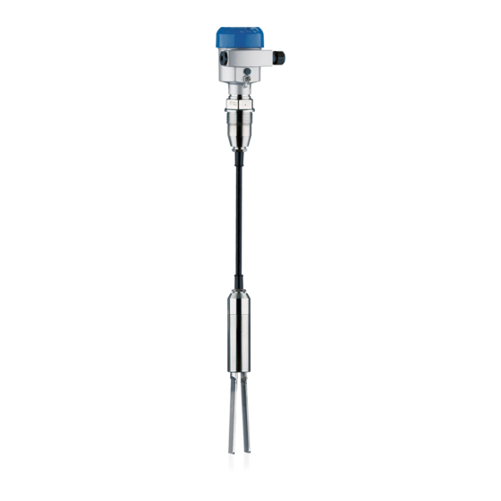
Fig. 1: OPTISWITCH 3200 C with plastic housing Housing cover Housing with electronics Process fitting 3.2 Principle of operation OPTISWITCH 3200 C is a level sensor with tuning fork for level Area of application detection. OPTISWITCH 3200 C - with relay output... - Page 8 Solid detection in water If OPTISWITCH 3200 C was ordered for detection of solids in water, the tuning fork is adjusted to the density of water. In the air or when covered by water (density: 1 g/cm³/0.036 lbs/in) OPTISWITCH 3200 C signals "uncovered".
-
Page 9: Operation
PE foam or PE foil is also used. Dispose of the packaging material via specialised recycling companies. Storage and transport temperature see "Supplement - Storage and transport tem- perature Technical data - Ambient conditions" Relative humidity 20 … 85 % OPTISWITCH 3200 C - with relay output... -
Page 10: Mounting
Mounting 4 Mounting 4.1 General instructions In general, OPTISWITCH 3200 C can be mounted in any Switching point position. The instrument must be mounted in such a way that the vibrating element is at the height of the requested switching point. -
Page 11: Mounting Instructions
filling and emptying apertures into account. To compensate measurement errors caused by the material cone in cylindrical vessels, the sensor must be mounted at a distance of d/6 from the vessel wall. OPTISWITCH 3200 C - with relay output... - Page 12 Mounting Fig. 3: Filling and emptying centered Fig. 4: Filling in the center, emptying laterally OPTISWITCH 3200 C Emptying opening Filling opening OPTISWITCH 3200 C - with relay output...
- Page 13 Fig. 5: Inflowing medium To minimise flow resistance caused by the tuning fork, Flows OPTISWITCH 3200 C should be mounted in such a way that the surfaces of the blades are parallel to the product movement. OPTISWITCH 3200 C - with relay output...
- Page 14 In applications such as grit chambers or settling basins for Baffle protection against fall- ing rocks coarse sediments, the vibrating element must be protected against damage with a suitable baffle. This baffle must be manufactured by you. OPTISWITCH 3200 C - with relay output...
- Page 15 Mounting >125 Fig. 7: Baffle protection against damages OPTISWITCH 3200 C - with relay output...
-
Page 16: Connecting To Voltage Supply
Take note of the general installation regulations. As a rule, connect OPTISWITCH 3200 C to vessel ground (PA), or in case of plastic vessels, to the next ground potential. On the side of the housing there is a ground terminal between the cable entries. -
Page 17: Wiring Plan, Single Chamber Housing
The electrical connection is hence finished. Fig. 8: Connection steps 5 and 6 5.3 Wiring plan, single chamber housing The following illustrations apply to the non-Ex as well as to the EEx d version. OPTISWITCH 3200 C - with relay output... - Page 18 DIL switch for mode adjustment Ground terminal Screwed terminals Control lamp We recommend connecting OPTISWITCH 3200 C in such a Wiring plan way that the switching circuit is open when there is a level signal, line break or failure (safe condition).
- Page 19 Connecting to voltage supply Fig. 11: Wiring plan Relay output Relay output Voltage supply OPTISWITCH 3200 C - with relay output...
-
Page 20: Set Up
Note: As a rule, always set the mode with mode switch (2) before starting the setup of OPTISWITCH 3200 C. The switching output will change if you set the mode switch (2) afterwards. This could possibly trigger other connected instruments or devices. -
Page 21: Function Chart
It is already preset and must only be modified in special cases. By default, the potentiometer of OPTISWITCH 3200 C is set to the right stop (>0.02 g/cm³ or >0.0008 lbs/in³). In case of very light-weight solids, turn the potentiometer to the left stop (>0.008 g/cm³... - Page 22 Relay energized Green Mode min. Dry run protection (6) (7) Relay deener- gized Failure of the supply voltage (min./max. mode) (6) (7) Relay deener- gized Failure (6) (7) Relay deener- flashes red gized OPTISWITCH 3200 C - with relay output...
-
Page 23: Maintenance And Fault Rectification
Fault rectification many cases, the causes can be determined this way and the faults rectified. OPTISWITCH 3200 C signals "covered" when the vibrating Checking the switching signal element is not submerged (overfill protection) OPTISWITCH 3200 C signals "uncovered" when the... -
Page 24: Exchange The Electronics
4 Pull the connection cables out of the terminals 5 Loosen the two screws with a screw driver (Torx size T10 or slot 4) Fig. 13: Loosen the screws Electronics module Screws (2 pcs.) OPTISWITCH 3200 C - with relay output... -
Page 25: Instrument Repair
Print and fill out one form per instrument Clean the instrument and pack it damage-proof Attach the completed form and possibly also a safety data sheet to the instrument OPTISWITCH 3200 C - with relay output... -
Page 26: Dismounting
Correct disposal avoids negative effects to persons and environment and ensures recycling of useful raw materials. Materials: see "Technical data" If you cannot dispose of the instrument properly, please contact us about disposal methods or return. OPTISWITCH 3200 C - with relay output... - Page 27 (DPDT), 2 floating spdts Turn-on voltage - min. 10 mV - max. 253 V AC, 253 V DC Switching current - min. 10 µA - max. 3 A AC, 1 A DC OPTISWITCH 3200 C - with relay output...
- Page 28 1x cable entry ½ NPT, 1x blind stopper ½ NPT, 1x cable entry ½ NPT 1x plug M12x1, 1x blind stopper M20x1.5 Spring-loaded terminals for wire cross-section up to 1.5 mm² (0.0023 in²) OPTISWITCH 3200 C - with relay output...
- Page 29 Electrical protective measures Protection IP 66/IP 67 Overvoltage category Protection class Approvals ATEX II 1/2G, 2G EExd d IIC T6 ATEX II 1/2 D IP66 T Deviating data in Ex applications: see separate safety instructions. OPTISWITCH 3200 C - with relay output...
- Page 30 ~ 69mm ") ") ø 77mm ") ø 84mm ø 77mm ") ") ") M20x1,5/ M20x1,5/ M20x1,5 ½ NPT ½ ½ NPT Fig. 14: Housing versions Plastic housing Stainless steel housing Aluminium housing OPTISWITCH 3200 C - with relay output...
- Page 31 Supplement G1½A ø 43mm (1 ") ø 11mm ( ") ø 43mm (1 ") Fig. 15: OPTISWITCH 3200 C, threaded version G1½ A = Sensor length, see "Technical data" OPTISWITCH 3200 C - with relay output...
- Page 32 Supplement OPTISWITCH 3200 C - with relay output...
- Page 33 Supplement OPTISWITCH 3200 C - with relay output...
- Page 34 Supplement OPTISWITCH 3200 C - with relay output...
- Page 35 Supplement OPTISWITCH 3200 C - with relay output...
- Page 36 Subject to change without notice 29957-EN-060830...
Need help?
Do you have a question about the OPTISWITCH 3200 C and is the answer not in the manual?
Questions and answers