KROHNE OPTISWITCH 3200 C Handbook
Vibrating level switch
Hide thumbs
Also See for OPTISWITCH 3200 C:
- Operating instructions manual (36 pages) ,
- Handbook (32 pages) ,
- Technical data sheet (19 pages)
Table of Contents
Advertisement
Quick Links
Advertisement
Table of Contents

Related Manuals for KROHNE OPTISWITCH 3200 C


Summary of Contents for KROHNE OPTISWITCH 3200 C
- Page 1 OPTISWITCH 3200 C Handbook Vibrating Level Switch NAMUR...
-
Page 2: Table Of Contents
Exchanging the electronics module ................24 How to proceed if a repair is necessary ................25 Dismount..........................26 Dismounting steps......................26 Disposal ......................... 26 Supplement ..........................27 Technical data ........................ 27 Dimensions ........................30 Trademark ........................32 OPTISWITCH 3200 C • NAMUR... - Page 3 Contents Safety instructions for Ex areas Take note of the Ex specific safety instructions for Ex applications. These instructions are attached as documents to each instrument with Ex approval and are part of the operating instructions. Editing status: 2018-11-22 OPTISWITCH 3200 C • NAMUR...
-
Page 4: About This Document
The dot set in front indicates a list with no implied sequence. Sequence of actions Numbers set in front indicate successive steps in a procedure. Battery disposal This symbol indicates special information about the disposal of bat- teries and accumulators. OPTISWITCH 3200 C • NAMUR... -
Page 5: For Your Safety
During work on and with the device, the required personal protective equipment must always be worn. Appropriate use The OPTISWITCH 3200 C is a sensor for point level detection. You can find detailed information about the area of application in chapter " Product description". Operational reliability is ensured only if the instrument is properly used according to the specifications in the operating instructions manual as well as possible supplementary instructions. -
Page 6: Safety Label On The Instrument
The EU conformity declaration can be found on our homepage. SIL conformity OPTISWITCH 3200 C meets the requirements to the functional safety according to IEC 61508. Further information is available in the Safety Manual "OPTISWITCH 3XXX". -
Page 7: Product Description
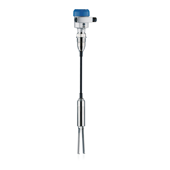
The scope of delivery encompasses: • OPTISWITCH 3200 C point level switch • Documentation – This operating instructions manual – Ex specific safety instructions (with Ex versions), if necessary further certificates The OPTISWITCH 3200 C consists of the components: Constituent parts • Housing lid • Housing with electronics • Process fitting with tuning fork Fig. -
Page 8: Principle Of Operation
3 Product description Principle of operation Application area OPTISWITCH 3200 C is a point level sensor with tuning fork for point level detection. It is designed for industrial use in all areas of process technology and is preferably used for bulk solids. -
Page 9: Storage And Transport
Technical data - Ambient conditions" • Relative humidity 20 … 85 % Lifting and carrying With instrument weights of more than 18 kg (39.68 lbs) suitable and approved equipment must be used for lifting and carrying. OPTISWITCH 3200 C • NAMUR... -
Page 10: Mounting
DIN/EN/IEC/ANSI/ISA/UL/CSA 61010-1. It can be used indoors as well as outdoors. Switching point In general, OPTISWITCH 3200 C must be mounted vertically. The instrument must be mounted in such a way that the vibrating element is at the height of the requested switching point. -
Page 11: Mounting Instructions
4 Mounting Fig. 2: Measures against moisture ingress Transport Do not hold OPTISWITCH 3200 C on the vibrating element. Espe- cially with flange and tube versions, the sensor can be damaged by the weight of the instrument. Remove the protective cover just before mounting. Pressure/Vacuum The process fitting must be sealed if there is gauge or low pressure in the vessel. Before use, check if the sealing material is resistant against the measured product and the process temperature. - Page 12 The tuning fork must be mounted in a way that takes the arrangement of the filling and emptying apertures into account. To compensate measurement errors caused by the material cone in cylindrical vessels, the sensor must be mounted at a distance of d/6 from the vessel wall. Fig. 3: Filling and emptying centred OPTISWITCH 3200 C • NAMUR...
- Page 13 The vibrating element should protrude into the vessel to avoid buildup. For that reason, avoid using mounting bosses for flanges and screwed fittings. This applies particularly to use with adhesive products. Inflowing medium If OPTISWITCH 3200 C is mounted in the filling stream, unwanted false measurement signals can be generated. For this reason, mount OPTISWITCH 3200 C at a position in the vessel where no disturbanc- es, e.g. from filling openings, agitators, etc., can occur. OPTISWITCH 3200 C • NAMUR...
- Page 14 4 Mounting Fig. 5: Inflowing medium Product flow To make sure the tuning fork of OPTISWITCH 3200 C generates as little resistance as possible to product flow, mount the sensor so that the surfaces are parallel to the product movement. Fig. 6: Flow orientation of the tuning fork Marking with screwed version 2 Direction of flow Baffle protection against...
- Page 15 4 Mounting > 125 mm (> 5") Fig. 7: Baffle for protection against mechanical damage OPTISWITCH 3200 C • NAMUR...
-
Page 16: Connecting To Power Supply
Cover all housing openings conforming to standard according to EN 60079-1. Connection procedure With Ex instruments, the housing cover may only be opened if there is no explosive atmosphere present. Proceed as follows: 1. Unscrew the housing lid OPTISWITCH 3200 C • NAMUR... -
Page 17: Wiring Plan, Single Chamber Housing
10. If necessary, carry out a fresh adjustment 11. Screw the housing lid back on The electrical connection is finished. Wiring plan, single chamber housing The following illustrations apply to the non-Ex as well as to the Ex-d version. OPTISWITCH 3200 C • NAMUR... - Page 18 In shipping condition, terminals 3 and 4 are bridged. For additional information see "Recurring function test". 1 2 3 4 Fig. 11: Wiring plan - External simulation key 1 NAMUR amplifier Bridge External simulation key OPTISWITCH 3200 C • NAMUR...
-
Page 19: Setup
(1) It is already preset and must only be modified in special cases. By default, the potentiometer of OPTISWITCH 3200 C is set to the right stop (> 0.02 g/cm³ or 0.0008 lbs/in³). In case of very light-weight solids, turn the potentiometer to the left stop (> 0.008 g/cm³ or 0.0003 lbs/in³). -
Page 20: Function Table
• dark = Low current ≤ 1.0 mA • yellow (flashing) = Failure ≤ 1.0 mA Function table Level switch OPTISWITCH 3200 C The following table provides an overview of the switching conditions depending on the set mode and the level. Note: The mode setting on the NAMUR amplifier must be selected in such a way that the switching output takes on safe state in case of failure (I ≤ 1 mA). -
Page 21: Proof Test (Sil)
NAMUR electronics module WE60N. For this purpose, the switching delay must be set to 0.5 s. OPTISWITCH 3200 C has an integrated simulation key. The simulation key is lowered on the electronics module. Push the simulation key for > 2 seconds. - Page 22 (1.5 s ±0.5 s) 3. Return to the actual operating con- dition You can carry out the function test with the stated current values also directly with a safety PLC or a process control system. OPTISWITCH 3200 C • NAMUR...
-
Page 23: Maintenance And Fault Rectification
Check the vibrating element and the sensor for buildup ement and remove the buildup if there is any. Wrong characteristic se- Set the correct characteristics on the characteristics re- lected versal switch (overflow protection, dry run protection). Wiring should be carried out according to the idle cur- rent principle. OPTISWITCH 3200 C • NAMUR... -
Page 24: Exchanging The Electronics Module
6. Pull out the old electronics module 7. Compare the new electronics module with the old one. The type label of the electronics module must correspond to that of the old electronics module. This applies particularly to instruments used in hazardous areas. OPTISWITCH 3200 C • NAMUR... -
Page 25: How To Proceed If A Repair Is Necessary
14. Check cable gland on tightness. The seal ring must completely encircle the cable. 15. Screw the housing lid back on The electronics exchange is now finished. How to proceed if a repair is necessary If it is necessary to repair the instrument, please contact the responsi- ble Krohne agency. OPTISWITCH 3200 C • NAMUR... -
Page 26: Dismount
With Ex instruments, the housing cover may only be opened if there is no explosive atmosphere present. Disposal The device is made of recyclable materials. For this reason, it should be disposed of by a specialist recycling company. Observe the ap- plicable national regulations. OPTISWITCH 3200 C • NAMUR... -
Page 27: Supplement
40 … +302 °F) optionally Max. permissible tensile load 3000 N (675 lbs) Sensor length (L) Ʋ PUR suspension cable 0.48 … 80 m (1.575 … 262.47 ft) (-20 … +80 °C/-4 … +176 °F) OPTISWITCH 3200 C • NAMUR... - Page 28 Ʋ Verschlusskappe ½ NPT Wire cross-section (spring-loaded terminals) Ʋ Massive wire, stranded wire 0.2 … 2.5 mm² (AWG 24 … 14) Ʋ Stranded wire with end sleeve 0.2 … 1.5 mm² (AWG 24 … 16) OPTISWITCH 3200 C • NAMUR...
- Page 29 IP 68 (1 bar) Type 6P Altitude above sea level up to 5000 m (16404 ft) Protection class Approvals Depending on the version, instruments with approvals can have different technical data. For these instruments, please note the corresponding approval documents. They are included in the scope of delivery. OPTISWITCH 3200 C • NAMUR...
-
Page 30: Dimensions
ø 77mm (2.72") ø 84mm ø 77mm (3.03") (3.31") (3.03") M20x1,5/ M20x1,5/ M20x1,5/ M20x1,5 ½ NPT ½ NPT ½ NPT Fig. 15: Housing versions Plastic single chamber Stainless steel single chamber Aluminium - single chamber OPTISWITCH 3200 C • NAMUR... - Page 31 9 Supplement G1½ ø 43 mm (1.69") ø 11 mm (0.43") ø 43 mm (1.69") Fig. 16: OPTISWITCH 3200 C, threaded version G1½ (DIN ISO 228/1) Sensor length, see chapter "Technical data" OPTISWITCH 3200 C • NAMUR...
-
Page 32: Trademark
9 Supplement Trademark All the brands as well as trade and company names used are property of their lawful proprietor/ originator. OPTISWITCH 3200 C • NAMUR... - Page 33 Notes OPTISWITCH 3200 C • NAMUR...
- Page 34 Notes OPTISWITCH 3200 C • NAMUR...
- Page 35 Notes OPTISWITCH 3200 C • NAMUR...
- Page 36 • Engineering, commissioning, calibration, maintenance and train- ing services Head Office KROHNE Messtechnick GmbH Ludwig-Krohne-Straße 5 47058 Duisburg (Germany) Tel.: +49 (0) 203 301 0 Tel.: +49 (0) 203 301 10389 info@krohne.de The current list of all KROHNE contacts and addresses can be found at: www.krohne.com...
Need help?
Do you have a question about the OPTISWITCH 3200 C and is the answer not in the manual?
Questions and answers