Advertisement
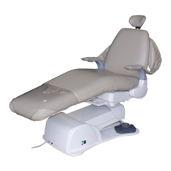
DENTAL CHAIR
This manual provides installation instructions for the BEL-50 Chair.
The instructions contained in this booklet should be throughly read and
understood before installation of the chair.
After the installation has been completed, keep this manual in a safe place.
INSTALLATION
INSTRUCTIONS
IMPORTANT
BEL-50
R
1E0570DE
Advertisement

Subscribe to Our Youtube Channel
Related Manuals for Belmont X-Calibur V BEL-50


Summary of Contents for Belmont X-Calibur V BEL-50
- Page 1 BEL-50 DENTAL CHAIR INSTALLATION INSTRUCTIONS IMPORTANT This manual provides installation instructions for the BEL-50 Chair. The instructions contained in this booklet should be throughly read and understood before installation of the chair. After the installation has been completed, keep this manual in a safe place. 1E0570DE...
-
Page 3: Table Of Contents
Table of Contents --------------------------------------- 1 Overview and Major Components 2. Dimensions and ----------------------------------------- 2 Specifications 3. Introduction -------------------------------------------------------------- 3 4. Installation --------------------------------------------------------------- 4 ----------------------------------------------------------------- 8 Adjustment ----------------------------------------------------------10 Electric Diagram... - Page 4 Intended Use of the Product This product is intended for the exclusive use for diagnoses, treatments and relative procedures of dentistry, and must be operated or handled by the qualified dentists or by dental staffs under the supervision of the dentist.Such dentists or dental staffs should instruct and/or assist the patients to approach to and leave from the product.
-
Page 5: Overview And Major Components
1. Overview and Major Components Figure 1 1. Headrest Assembly 17. Sub Link Cover(Lower) 9. Seat Cushion 2. Backrest Cushion 18. Main Power Switch 10.Backrest Cover 3. Armrest 19. Fuse Holder 11.Seat Back Support 4. Main Link Cover 20. Backrest Control Panels 12.Dome Casting Cover 5. -
Page 6: Dimensions And Specifications
Dimensions and Specifications 2-1. Dimensions (Inches) 74-1/4 23-5/8 18-1/2 5-1/4 17-9/16 34-3/4 74-1/4 15-7/8 34-3/4 22-1/4 23-1/4 23-7/8 24-1/2 34-3/4 70˚ 20˚ 6˚ 20˚ 6˚ 10˚ 34-3/4 22-1/4 2-2. Specifications * Sealed hydraulic system powered by 3.5 A motor pump * Base plate: 1/2"... -
Page 7: Introduction
Introduction 3-1. Precautions for Installation • Keep the equipment away from water. • Keep in a circumstances safe from influence by temparature, humidity, wind, sun light, air containing salts and minerals. • Care about stability such as inclination, vibration and impact, including handling and transportation. •... -
Page 8: Installation
4. Installation 4-1. Unpacking the Chair Base 1) Place chair carton close to installation location. Remove all the staples fixing the carton to pallet, or cut the carton just above the stapled line, and remove the carton. (See Figure 1.) Staples 2) Using a 10mm socket, loosen and remove Figure 1... - Page 9 4-2. Installation 1) Plug chair into 120VAC outlet. CAUTION To avoid the risk of electrick shock, this equipment must only be connected to a supply mains with protective earth. Grounding reliability can only archieved when the equipment is connected to an equivalent receptacle marked HOSPITAL ONLY or HOSPITAL GRADE.
- Page 10 7) Re-attach plastic backrest cover to Eyelet Holes backrest frame, as follows; Alignment Bolts a) Insert backrest cover alignment bolts into eyelet holes in backrest frame, as shown in figure 6a. b) Connect wire harness from back Backrest rest membrane switches to Frame connector PC Board on the Back Backrest Cover...
- Page 11 9) Raise the chair to upper position. Fix the seat to base section by using 2 round head screws (1/4 - 20 x 3/4) and 2 flat head screws (1/4 - 20 x 1-3/8). (See Figure 6d) Flat Head Screw (1/4 - 20 x 1-3/8 ) Round Head Screw (1/4 - 20 x 3/4 )
-
Page 12: Adjustment
5. Adjustment 5-1. Speed Controls (Figures 9a and 9b) Seat lowering speed and backrest reclining speed can be adjusted by the speed control knob on the solenoid valve block. The solenoid valve numbers and functions are shown in Fig.9b. A. Remove the pump cover. The solenoid valve block is located on the left side at the front of the chair base. - Page 13 IMPORTANT To avoid a malfunction when setting lower limit, make sure that there is clearance between the safety plate and the chair base. If a swing mounted delivery system is attached to the chair, set lower travel limit so delivery system components do not contact chair pump and cantilever lift arm covers.
-
Page 14: Electric Diagram
6. Electric Diagram - 10 -... - Page 16 Importer for U.S.A. BELMONT EQUIPMENT, Division of Takara Belmont USA, Inc. 101 Belmont Drive, Somerset, New Jersey 08873 U.S.A. TEL.:(732) 469-5000 / (800) 223-1192 FAX.:(732)526-6322 / (800) 280-7504 Importer for Canada TAKARA COMPANY, CANADA, LTD. 2455 Meadowvale Blvd. Mississauga, Ontario L5N 5S2, Canada TEL:(905)816-8965 www.belmont.ca...
Need help?
Do you have a question about the X-Calibur V BEL-50 and is the answer not in the manual?
Questions and answers