Table of Contents
Advertisement
Quick Links
Advertisement
Table of Contents

Subscribe to Our Youtube Channel
Related Manuals for SIIG AV-GM04P3-S1


Summary of Contents for SIIG AV-GM04P3-S1
- Page 1 HDMI2.0 over IP Multicast System with video support P/N: AV-GM04P3-S1...
-
Page 2: Table Of Contents
However, like all electronic equipments, the AV-GM04P3-S1 should be used with care. Please read and follow the safety instructions to protect yourself from possible injury and to minimize the risk of damage to the unit. -
Page 3: Introduction
With broadcasting management software and Gigabit Ethernet network switch (supporting IGMP, Jumbo frame), AV-GM04P3-S1 is a complete UHD video broadcasting solution for digital signage. It can transmit Full HD 4K2K60 HDMI video broadcasting over IP network. The broadcasting format can be Point to Point, Point to Many, and Multi-Casting. -
Page 4: Package Contents
PACKAGE CONTENTS AV-GM04P3-S1-TX AV-GM04P3-S1-RX ● 1x AV-GM04P3-S1-RX ● 1x AV-GM04P3-S1-TX ● 1x IR receiver cable ● 1x IR blaster cable ● 1x 5V2A Power adaptor ● 1x 5V2A Power adaptor ● 1x User Manual ● 1x User Manual ● 1x IR receiver cable ●... -
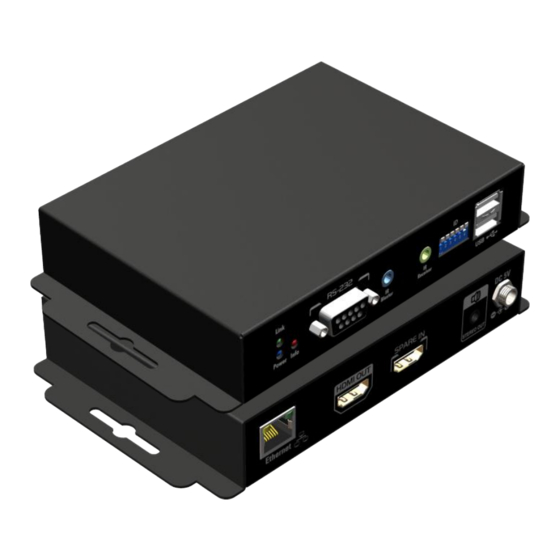
Page 5: Panel Descriptions
20~90% RH [no condensation] PANEL DESCRIPTIONS Transmitting unit ► AV-GM04P3-S1-TX RJ-45: Gigabit Ethernet port HDMI loopout: Connect to a HDMI display with a HDMI male-male cable. HDMI IN: Connects to a HDMI source with a HDMI male-male cable Analog audio line in: Connect to upstream speaker output... - Page 6 Alarm LED indicator RS-232: Connect to PC serial port with a DSUB-9 male-male cable here IR Blaster: Infrared 3.5mm socket for plugging in the extension cable of IR blaster IR Receiver: Infrared 3.5mm socket for plugging in the extension cable of IR receiver Dip Switch: Video channel selection USB: Connect to upstream USB host Dip Switch: RS-232 mode selection, [ON] debug mode;...
-
Page 7: Receiving Unit
Receiving unit ► AV-GM04P3-S1-RX RJ-45: Gigabit Ethernet port HDMI OUT: Connect to a HDMI display with a HDMI male-male cable. HDMI IN: Connects to a HDMI source with a HDMI male-male cable Analog audio line out: Connect to downstream headphone output... - Page 8 Notes: TX/RX group ID dip-switch setting 1. For ID=1~63, please refer the table below to set up (Hardware control) 2. For ID=64~1023, please adjust the DIP switch to ID=0, and the real ID can be decided by the external software (Software control) ID Pin1 Pin2 Pin3 Pin4 Pin5 Pin6 ID Pin1 Pin2 Pin3 Pin4 Pin5 Pin6 ↓...
-
Page 9: Connection Diagram
↓ ↑ ↑ ↑ ↑ ↓ ↓ ↑ ↑ ↑ ↑ ↑ ↑ ↑ ↑ ↑ ↑ ↓ ↑ ↑ ↑ ↑ ↑ ↑ CONNECTION DIAGRAM... -
Page 10: Ir Pass-Through
IR PASS-THROUGH IR Extenders IR Blaster IR Receiver IR Sockets IR BLASTER: plug in the IR blaster to emit all IR command signals received from the IR receiver from the other end to control the devices corresponding to the IR signals. IR RECEIVER: plug in the IR receiver to receive all IR command signals from the IR remote controls of the corresponding devices. -
Page 11: Warranty
The SELLER will NOT be liable for direct, indirect, incidental, special, or consequential damages resulting from any defect or omission in this manual, even if advised of the possibility of such damages. Also, the technical information contained herein regarding the AV-GM04P3-S1 features and specifications is subject to change without further notice.
Need help?
Do you have a question about the AV-GM04P3-S1 and is the answer not in the manual?
Questions and answers