Table of Contents
Advertisement
Quick Links
OPERATOR'S MANUAL
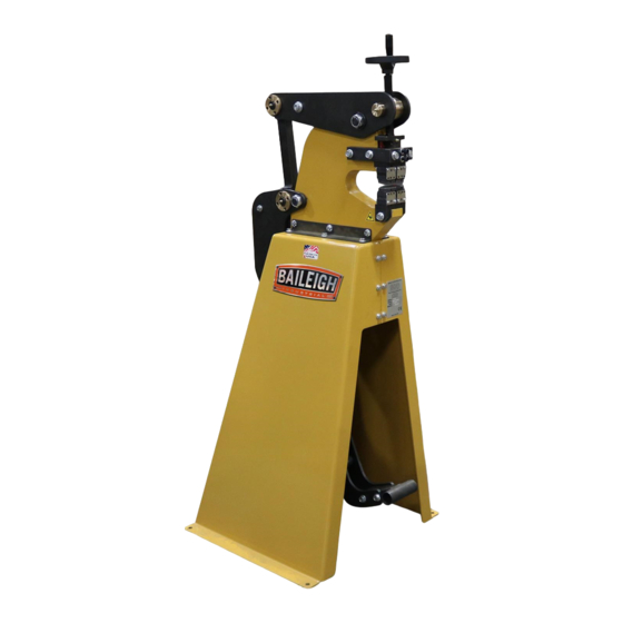
METAL FORMING SHRINKER STRETCHER
MODEL: MSS-14F
Baileigh Industrial, Inc.
P.O. Box 531
Manitowoc, WI 54221-0531
Phone: 920.684.4990
Fax: 920.684.3944
sales@baileigh.com
REPRODUCTION OF THIS MANUAL IN ANY FORM WITHOUT WRITTEN APPROVAL OF BAILEIGH INDUSTRIAL, INC.
IS PROHIBITED. Baileigh Industrial, Inc. does not assume and hereby disclaims any liability for any damage or loss
caused by an omission or error in this Operator's Manual, resulting from accident, negligence, or other occurrence.
Rev. 12/2018
© 2018 Baileigh Industrial, Inc.
Advertisement
Table of Contents

Subscribe to Our Youtube Channel
Related Manuals for Baileigh Industrial MSS-14F


Summary of Contents for Baileigh Industrial MSS-14F
- Page 1 REPRODUCTION OF THIS MANUAL IN ANY FORM WITHOUT WRITTEN APPROVAL OF BAILEIGH INDUSTRIAL, INC. IS PROHIBITED. Baileigh Industrial, Inc. does not assume and hereby disclaims any liability for any damage or loss caused by an omission or error in this Operator’s Manual, resulting from accident, negligence, or other occurrence.
-
Page 2: Table Of Contents
Table of Contents THANK YOU & WARRANTY ..................1 INTRODUCTION ......................3 GENERAL NOTES ......................3 SAFETY INSTRUCTIONS ....................4 SAFETY PRECAUTIONS ....................6 Dear Valued Customer: ....................6 TECHNICAL SPECIFICATIONS ..................8 TECHNICAL SUPPORT ....................8 UNPACKING AND CHECKING CONTENTS ..............9 Cleaning ........................ -
Page 3: Thank You & Warranty
THANK YOU & WARRANTY Thank you for your purchase of a machine from Baileigh Industrial. We hope that you find it productive and useful to you for a long time to come. Inspection & Acceptance. Buyer shall inspect all Goods within ten (10) days after receipt thereof. Buyer’s payment shall constitute final acceptance of the Goods and shall act as a waiver of the Buyer’s rights to inspect or... - Page 4 • A 30% re-stocking fee applies to all returns. Baileigh Industrial makes every effort to ensure that our posted specifications, images, pricing and product availability are as correct and timely as possible. We apologize for any discrepancies that may occur. Baileigh Industrial reserves the right to make any and all changes deemed necessary in the course of business including but not limited to pricing, product specifications, quantities, and product availability.
-
Page 5: Introduction
After receiving your equipment remove the protective container. Do a complete visual inspection, and if damage is noted, photograph it for insurance claims and contact your carrier at once, requesting inspection. Also contact Baileigh Industrial and inform them of the unexpected occurrence. Temporarily suspend installation. -
Page 6: Safety Instructions
IMPORTANT PLEASE READ THIS OPERATORS MANUAL CAREFULLY It contains important safety information, instructions, and necessary operating procedures. The continual observance of these procedures will help increase your production and extend the life of the equipment. SAFETY INSTRUCTIONS LEARN TO RECOGNIZE SAFETY INFORMATION This is the safety alert symbol. - Page 7 SAVE THESE INSTRUCTIONS. Refer to them often and use them to instruct others. PROTECT EYES Wear safety glasses or suitable eye protection when working on or around machinery. PROTECT AGAINST NOISE Prolonged exposure to loud noise can cause impairment or loss of hearing.
-
Page 8: Safety Precautions
SAFETY PRECAUTIONS Metal working can be dangerous if safe and proper operating procedures are not followed. As with all machinery, there are certain hazards involved with the operation of the product. Using the machine with respect and caution will considerably lessen the possibility of personal injury. However, if normal safety precautions are overlooked or ignored, personal injury to the operator may result. - Page 9 7. Dressing material edges. Always chamfer and deburr all sharp edges. 8. Do not force tool. Your machine will do a better and safer job if used as intended. DO NOT use inappropriate attachments in an attempt to exceed the machines rated capacity. 9.
-
Page 10: Technical Specifications
TECHNICAL SPECIFICATIONS Mild Steel Capacity 14ga. (0.0747” [1.897mm]) Aluminum Capacity 12ga. (0.0808” [2.052mm]) Movement Manual, Foot Pedal Throat Depth 7" (178mm) Stand Included Shipping Weight 300 lbs. (136kg) Shipping Dimensions 60" x 44" x 66" (1524 x 1118 x 1677mm) Based on a material tensile strength of *60000 PSI –... -
Page 11: Unpacking And Checking Contents
UNPACKING AND CHECKING CONTENTS Your Baileigh machine is shipped complete. Separate all parts from the packing material and check each item carefully. Make certain all items are accounted for before discarding any packing material. WARNING: SUFFOCATION HAZARD! Immediately discard any plastic bags and packing materials to eliminate choking and suffocation hazards to children and animals. -
Page 12: Transporting And Lifting
TRANSPORTING AND LIFTING NOTICE: Lifting and carrying operations should be carried out by skilled workers, such as a truck operator, crane operator, etc. If a crane is used to lift the machine, attach the lifting chain carefully, making sure the machine is well balanced. Follow these guidelines when lifting with truck or trolley: •... -
Page 13: Anchoring The Machine
• Remove scrap and waste materials regularly, and make sure the work area is free from obstructing objects. • If long lengths of material are to be fed into the machine, make sure that they will not extend into any aisles. •... -
Page 14: Getting To Know Your Machine
GETTING TO KNOW YOUR MACHINE Item Description Function Foot Pedal Press treadle the pedal to clamp and release the jaws. Connects the foot pedal to the rocker arm to activate Connecting Linkage the clamping and releasing action for the dies. Gap Adjustment Increases or decrease the jaw gap. -
Page 15: Assembly And Set Up
ASSEMBLY AND SET UP WARNING: For your own safety, DO NOT connect the machine to the power source until the machine is completely assembled and you read and understand the entire instruction manual. Tooling Installation: This set up show how the tools should be installed for shrinking. - Page 16 In this view it shows the top die assemblies removed so you can see the jaw orientation. The jaws with serrations are to be used for shrinking. In this view it will shows how to remove the jaw caps. Insert a screw driver into the machined slot to break the magnetic force.
- Page 17 Once the force from the magnet is released, grab onto the assembly and remove. In this view it shows the jaws installed for stretching. Note that the markings “U” are now pointing together, This is the reversing of the jaws from shrinking.
-
Page 18: Jaws
Here you will see both top and bottom mechanisms installed for stretching. Both show the “U” pointing at each other Also notice that the screw heads (A) point away from the material gap (B). Here is a completed setup for stretching. JAWS •... -
Page 19: Operation
OPERATION WARNING: DO NOT step on the foot pedal without having work material between the jaws. The jaws may chip or break causing injury from flying objects. CAUTION: Always wear proper eye protection with side shields, safety footwear, and leather gloves to protect from burrs and sharp edges. Keep hands and fingers clear of the dies. -
Page 20: Material Selection
Try using the tool with a sample piece of metal to get a feel for how it operates. Place the material in the middle of the jaw box and step down on the foot pedal to form the metal. Work the leading edge of the material first to break down the initial resistance of the metal. -
Page 21: Lubrication And Maintenance
LUBRICATION AND MAINTENANCE WARNING: Make sure the electrical disconnect is OFF before working on the machine. Maintenance should be performed on a regular basis by qualified personnel. Always follow proper safety precautions when working on or around any machinery. • Check daily for any unsafe conditions and fix immediately. •... -
Page 22: Parts Diagram
PARTS DIAGRAM... -
Page 26: Parts List
Parts List Item Part Number Description Qty. ME-PS16-6A001 Main Frame MS16-6A001 Main Lever PS16-7A002 Drive Shaft ME-PS16-6A003 Support Finger ME-PS16-6A002 Tie Bar MS16-6A005 Connecting Rod PS16-7A009 Actuator Screw ME-PS16-7A003 Spacer PS16-6A006 Slide Gib PS16-6A014 Top Master Die Mount PS16-6A013-V2 Jaw Insert Interlocking PS16-6A005-V2 Lower Base Plate CALL... - Page 27 Item Part Number Description Qty. M12 X 1.75 X 20 Hex Flange 1/4-20 X .50 SHCS M8 X 1.25 X 25 SHCS 1" External Retaining Ring STD. Straight Grease Zerk M16 X 2.0 X 30 Hex Flange M12 X 1.75 X 40 Hex Flange M12 X 1.75 X 30 Hex Flange...
- Page 28 , WI 54220 UFEK RIVE ANITOWOC : 920. 684. 4990 F : 920. 684. 3944 HONE www.baileigh.com BAILEIGH INDUSTRIAL, INC. 1455 S. C , CA 91761 AMPUS VENUE NTARIO : 920. 684. 4990 F : 920. 684. 3944 HONE BAILEIGH INDUSTRIAL LTD. U...
Need help?
Do you have a question about the MSS-14F and is the answer not in the manual?
Questions and answers