Table of Contents
Advertisement
Quick Links
Advertisement
Table of Contents

Related Manuals for Optical Systems Design OSD2258


Summary of Contents for Optical Systems Design OSD2258
-
Page 1: Index
Quick Start Guide OSD2258 10-PORT REDUNDANT RING GIGABIT ETHERNET SWITCH... -
Page 3: Table Of Contents
OPTICAL SYSTEMS DESIGN INDEX 1 INTRODUCTION ........................4 INSTALLATION........................4 LOCATION ..........................4 OSD2258 FRONT AND REAR PANELS................. 5 FRONT PANEL ........................5 TOP P ..........................6 ANEL BOTTOM PANEL ........................6 POWER SUPPLY CONNECTIONS ..................7 ALARM CONNECTIONS ......................7 SWITCH CONFIGURATION .................... -
Page 4: Introduction
Protective eyewear should be worn in the vicinity of laser equipment. LOCATION As with any electric device, the OSD2258 should be placed where it will not be subjected to extreme temperatures, humidity, or electromagnetic interference. Specifically, the site selected should meet the following requirements: •... -
Page 5: Osd2258 Front And Rear Panels
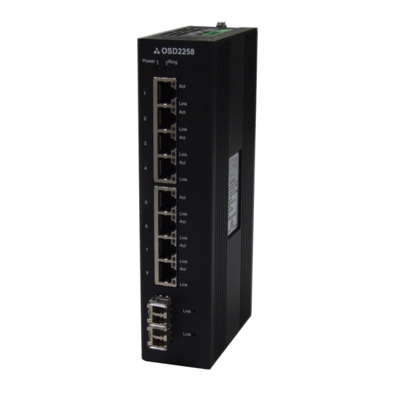
OPTICAL SYSTEMS DESIGN 3 OSD2258 FRONT AND REAR PANELS FRONT PANEL Power Ring LED Activity LED (x 8) Ports 1-4 RJ45 Copper Link LED Ports (x 10) Ports 5-8 RJ45 Copper Ports Ports 9-10 SFP Fiber Ports FIGURE 1: FRONT PANEL... -
Page 6: Top Panel
Alarm Redundant 1 LED 2 LED Output Power Input (1&2) FIGURE 2: TOP PANEL BOTTOM PANEL 8-Way Mini USB CLI USB Configuration Programming Console Switches Port Port FIGURE 3: BOTTOM PANEL DOC ID: 10117602 PAGE 6 OSD2258 QUICK START GUIDE... -
Page 7: Power Supply Connections
@ 10VA 5 Alarm Connections The OSD2258 has two monitoring alarm outputs: 1) Ring to Bus Alarm and 2) Temperature Alarm. The alarm connections and conditions for alarm outputs are as set out in Table 2. There are four pins on the 3.5mm terminal block used alarm output. -
Page 8: Switch Configuration
6 Switch Configuration The OSD2258 has an 8-way DIP switch located on the bottom of the unit to control a number of functions. Table 3 outlines the function of each switch. Default position of switch 1-8 is all Off (down position) –... -
Page 9: Led Indicators
Removing SFP – Remove fiber connector. Pull the SFP lever down to unlock SFP from housing. Using the lever, gently pull the SFP out. Fiber SFP Inserting Removing FIGURE 6: FITTING/REMOVING SFP CONNECTORS DOC ID: 10117602 PAGE 9 OSD2258 QUICK START GUIDE... -
Page 10: Cli Overview
OPTICAL SYSTEMS DESIGN 9 CLI OVERVIEW CONNECT TO CLI The Silicon Laboratories CP210x VCP Drivers is needed to be installed on the PC before connecting the switch. DOC ID: 10117602 PAGE 10 OSD2258 QUICK START GUIDE... -
Page 11: Cli Command Sfor Ip Configuration
• Parity: None • Stop Bits: 1 Flow Control: None • 3. Check the link by pressing <ENTER>. The line should jump to the next line. CLI COMMANDS FOR IP CONFIGURATION DOC ID: 10117602 PAGE 11 OSD2258 QUICK START GUIDE... -
Page 12: Gui Overview
(i.e.: 192.168.0.2). In a web browser, enter the URL default 192.168.0.99. • The GUI should now have access to the OSD2258 through the web browser • Configuration settings, Monitoring and Maintenance can all be accessed vis the drop down •... -
Page 13: Ip Configuration
CLI (see section 9) should be used. Note: All previous settings will be erased! default_setting Function: Reset configuration to default. Format: {ds} DOC ID: 10117602 PAGE 13 OSD2258 QUICK START GUIDE... -
Page 14: Warranty
For warranty period, please call your local OSD distributor. 12.2 REPAIRS Optical Systems Design reserves the right to repair or replace faulty modules/units. Please obtain a “Return Material Authorisation” (RMA) form and number before returning goods. Goods must be returned in adequate packing material to Optical Systems Design, Warriewood or its nominated authorised representative, for all repairs. - Page 15 OPTICAL SYSTEMS DESIGN DOC ID: 10117602 PAGE 15 OSD2258 QUICK START GUIDE...
- Page 16 Optical Systems Design Pty. Ltd. OPTIC L 7/1 Vuko Pl. Warriewood 2102 P.O. Box 891 Mona Vale N.S.W. Australia 2103 SYSTEMS Telephone: +61 2 9913 8540 Facsimile: +61 2 9913 8735 Email: sales@osd.com.au DESIGN Web Site: www.osd.com.au PTY LTD A.B.N. 83 003 020 504...
- Page 17 OPTICAL SYSTEMS DESIGN Printed in Australia DOC ID: 10117602 PAGE 17 OSD2258 QUICK START GUIDE...