Advertisement
Quick Links
DURApulse GS30 EtherCAT Comm Card Installation Guide
Communication Card Installation
For the GS30A-CM-ECAT card, follow the steps in this guide to install to the GS30 drive in position 2.
NOTE: The GS30A-CM-ECAT must be installed in position 2 for all drives, it cannot be installed in position 1.
Position 1
Position 2
Mounting Positions for Frames A-D
Things you'll need (most of this will come with your communication card):
• Communication card to be installed
• External mounting cover
• Removable green terminal block
• Grounding wire
• Mounting screw
• Small phillips and straight screwdriver
• Connection cable - long. Installing to position 2 requires the long connection cable
(included with your card) regardless of GS30 drive size.
NOTE: The comm card connection port will be covered by a card installed in position 1. When installing cards in both positions, the cable
for the position 2 card must be connected to the drive before the position 1 support frame is installed.
NOTE: Ensure all control board and power wires are terminated before installing the option card. Once the option card is installed, there
is no access to the control terminals on all drives, and no access to the power terminals on frames A–D.
1) Disconnect power to the drive and wait until the capacitors are fully drained (at least 5 minutes).
2) Remove the front cover of the drive.
GS30A-CM-ECAT_QSP_1ed 04/27/2023
Scan code to view
installation animation
Position 1
Position 2
Mounting Positions for Frames E-I
3) Remove the plug terminal cover from the drive control board. A small
screwdriver can be used to pry the cover from the plug.
Option Card Cable-Drive
Connection Port
4) The EtherCat card must be grounded before wiring. A ground terminal wire is included with the card. The A side of the ground terminal connects to the PE on the drive
as indicated by the red circles below. The B side of the ground terminal connects to the green removeable terminal block labeled PE on the option card. Connect the
wire then plug the terminal block back into the option card. Note, for D-I frames, snip the "A" ring of the ground terminal wire to fit the connector around the ground
screw.
Ground Terminal Wire
A
B
NOTE: For Frames A-D, continue with the steps below. For Frames E-I skip to "Installation Steps for Frame E-I".
Installation Steps for Frames A-D
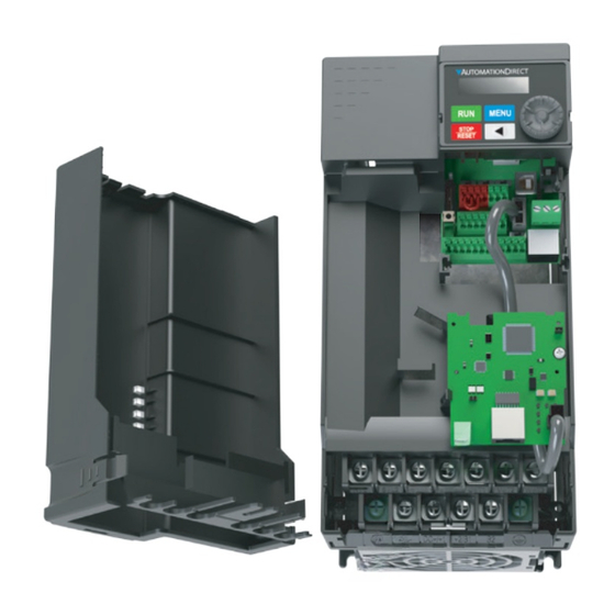
5) Detach the upper cover of the installation box and place the communication
card in the box with the terminal block and connector facing up and snap into
place.
7) Plug each end of the long control board connector cable included with the option card into the appropriate slot on the card and the drive. Apply enough pressure to
ensure the connector is properly locked in place.
8) Replace the front cover of the drive.
DURApulse GS30 EtherCAT Comm Card Installation Guide – 1st Ed 04/27/2023
Frame A–C
Frame D–F
Frame G
Frame H-I
6) Flip the installation box over and ensure the two clips are fully engaged. Then
fasten the screws as shown below (torque screws to 4-6 kg٠cm/3.5-5.2 lb-in/
0.39-0.59 N٠m).
Locked
Unlocked
9) Line up the four clips on the back of the installation box with the four slots on
the front of the GS30 drive. Press downward to engage the clips. Installation
is complete.
Page 1
Advertisement

Subscribe to Our Youtube Channel
Related Manuals for Automationdirect.com DURApulse GS30


Summary of Contents for Automationdirect.com DURApulse GS30
- Page 1 9) Line up the four clips on the back of the installation box with the four slots on the front of the GS30 drive. Press downward to engage the clips. Installation is complete. Option Card Cable-Drive Connection Port DURApulse GS30 EtherCAT Comm Card Installation Guide – 1st Ed 04/27/2023 Page 1 GS30A-CM-ECAT_QSP_1ed 04/27/2023...
- Page 2 8) Press downward to engage the clips, then fasten the screws as shown (torque 9) Replace the GS30 drive front cover. Installation is complete. screws to 4-6 kg٠cm/3.5-5.2 lb-in/ 0.39-0.59 N٠m).. DURApulse GS30 EtherCAT Comm Card Installation Guide – 1st Ed 04/27/2023 Page 2 GS30A-CM-ECAT_QSP_1ed 04/27/2023...
Need help?
Do you have a question about the DURApulse GS30 and is the answer not in the manual?
Questions and answers