Outback Excel 310 Assembly And Operating Instructions Manual
Gas bbq, 2 burner gas bbq
Hide thumbs
Also See for Excel 310:
- Assembly and operating instructions manual (27 pages) ,
- Assembly and operating instructions manual (25 pages)
Advertisement
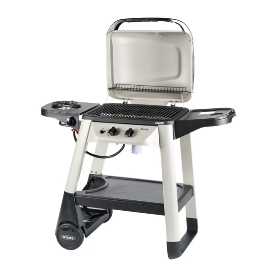
Assembly and Operating Instructions for Outback®
Excel 310 Gas BBQ and Excel Onyx 2 Burner Gas BBQ
EX310A
Photographs are not to scale.
Specifications subject to change
without prior notice.
For outdoor use only. Not for commercial use.
Read instructions before using the appliance. Failure to follow instructions
could result in death, serious bodily injury, and/or property loss.
Warning: accessible parts may be very hot. Keep young children and pets
away.
Do not move the appliance during use.
Turn off the gas supply at the gas bottle after use.
Any modification of the appliance, misuse, or failure to follow the instructions
may be dangerous and will invalidate your warranty. This does not affect your
statutory rights.
WARNING
Retain these instructions for future reference.
Leak test annually, and whenever the gas bottle is removed or replaced. Check
that the hose connections are tight and leak test each time you reconnect the
gas bottle.
For Flare-up control please refer to the 'OPERATION' section of this manual.
FOR YOUR SAFETY
If you smell gas:
1.
Shut off gas to the appliance.
2.
Extinguish any open flame.
3.
Open barbecue lid or hood.
4.
If odour continues, discontinue use and
contact your local dealer.
EX311A
FOR YOUR SAFETY
1.
Do
not
store or
use petrol or other
flammable vapours or liquids in the vicinity
of this or any other appliance.
2.
A gas bottle not connected for use must not
be stored in the vicinity of this or any other
appliance.
0359
Advertisement
Table of Contents

Related Manuals for Outback Excel 310


Summary of Contents for Outback Excel 310
- Page 1 Assembly and Operating Instructions for Outback® Excel 310 Gas BBQ and Excel Onyx 2 Burner Gas BBQ EX310A EX311A Photographs are not to scale. Specifications subject to change 0359 without prior notice. For outdoor use only. Not for commercial use.
-
Page 2: Parts List
Parts List Quantity varies according to model purchased. Specifications subject to change without prior notice. For more details on hardware, please see the corresponding ‘Hardware Reference Diagram’. CODE PART EX310A EX311A Hood (Pre-Assembled to Body) √ √ Hood Handle √ √... -
Page 3: Parts Diagram
Parts Diagram: Quantity varies according to model purchased. Specifications subject to change without prior notice. For more details on hardware, please see the corresponding ‘Hardware Reference Diagram’. - Page 4 Hardware Reference Diagram: Specifications subject to change without prior notice.
- Page 5 Assembly IMPORTANT! TOOLS NEEDED FOR ASSEMBLY: Medium size flat blade or Phillips/Crosspoint screwdriver, adjustable spanner or metric spanner set. The assembly of this barbecue requires 2 people. Whilst every care is taken in the manufacture of this product, care must be taken during assembly in ...
- Page 6 Attach right leg assembly to the bottom shelf assembly using M6x15 Bolts (D1x4pcs). Attach the Left Front Leg (C10) and Left Rear Leg (C11) to the Gas Bottle Holder (C14) using ST4.8x15 Screws (D7x4pcs).
- Page 7 C17 C18 Insert the Axle (C19) through the clamping brackets underneath the Gas Bottle Holder (C14) and tighten the clamping screws. Take care not to over tighten these screws which will damage the plastic gas bottle holder. Slide a Wheel Spacer (C16) over each end of the Axle (C19). Note: the spacers are packed in a plastic bag with the electrode, grease cup holder and grease cup.
- Page 8 Unscrew the locknut from the Heat Indicator (A4). Insert heat indicator through the Hood (A1) and fix it by tightening its locknut. Attach the Hood Handle (A2) and Hood Handle Heat Shield (A3) onto the hood using the M5x15 Bolts (D2x2pcs). Carefully place the Barbecue Body (B1) onto the tops of the legs.
- Page 9 Install a M6x15 Bolt (D1) and a Spacer (D11) into the upper fixing hole on each front leg. Place the Control Panel (B3) assembly in position by aligning the spacers with the slot on each side of control panel and fix it onto the trolley assembly using M6x15 Bolts (D1x2pcs). Feed the Grease Cup Holder (B14) through the hole in barbecue body.
- Page 10 √ View from underneath the body × Feed the Burner (B2) into barbecue body. Ensure that the burner venturi tubes are over the ends of the gas valves. They are a loose fit and not a gas tight seal. Secure the burner with the ST4.0x10 Screws (D5x2pcs).
- Page 11 Attach the Body Heat Shield (B12) to barbecue body using the M5x10 Bolts (D3x2pcs) and M5 Nuts (D10x2pcs). Attach the Flame Tamer Brackets (B5) to barbecue body using the M4x10 Bolts (D4x4pcs) and M4 Nuts (D9x4pcs).
- Page 12 Carefully lay the Flame tamer (B6) onto its brackets in the barbecue body, ensuring it lies level within the body. Lay the Cooking Grill (B7) into place. Step 1 Step 2 Step 3 Step 4 Attach the Warming Rack (A5) to the hood and barbecue body as shown. Make sure that the shorter, fixed legs go through the holes in the hood, then the swing legs fix to the body of the barbecue.
- Page 13 Attach the Side Shelf Bracket A (C2) and Side Shelf Bracket B (C3) to the Side Shelf (C1) using ST4.0x15 Screws (D6x4pcs). Slide a Shelf Spacer (D11) onto a M6x15 Bolt (D1) and screw it into the upper fixing point on the right rear leg as shown.
- Page 14 Attach the Side Burner Shelf (C6) to the left front and left rear legs using M6x15 Bolts (D1x4pcs). Remove the screws from Side Burner Valve / Hose Assembly (C9) and secure it to the side shelf with those 2 screws. Assemble the Side Burner Knob (C4) onto the side burner valve.
- Page 15 √ × Remove the wing nut from Side Burner (C7). Place the Side Burner Electrode (C8) onto the side burner shelf as shown. Then Place the side burner in position as above shown. Fit the side burner venturi tube over the gas valve outlet. This is a loose fit and not a gas tight seal.
- Page 16 Place the Side Burner Grid (C5) onto the side burner shelf. NOTE: Make sure the base of cooking utensil to put on the side burner is larger than 150mm and smaller than 220mm. Fix the Hose Clip (D12) into the upper hole of the front short leg using a ST4.0x10 Screw (D5), then feed the hose through the clip as shown.
-
Page 17: Leak Testing
Leak Test Diagram 1. Maximum diameter or breadth is 315mm. 2. Maximum height (regulator included) is 580mm. ASSEMBLY IS NOW COMPLETE. PROCEED TO THE NEXT PAGE FOR INSTRUCTIONS ON OPERATION AND MAINTENANCE ALL JOINTS AND CONNECTIONS MUST NOW BE LEAK TESTED BEFORE USING THE BARBECUE. -
Page 18: Gas, Regulator And Hose
Important Information Before you use your barbecue, perform a leak test. This is the only safe and sure way Please read these instructions carefully to detect any gas leaking from joints and before assembly and use of your barbecue. connections of the barbecue after assembly. -
Page 19: Installation
Installation surface, please use a long handled brush to apply a light coat of cooking or vegetable oil before each barbecuing session. (Note: Selecting a Location When cooking for the first time, paint colours This barbecue is for outdoor use only and may change slightly as a result. - Page 20 position for 3-5 minutes in order to pre-heat marinades sparingly and try to avoid very the barbecue. This should be done before cheap cuts of meat or meat products as each cooking session. The hood must be these tend to have a high fat and water open during preheating.
-
Page 21: Care And Maintenance
Outback® stockist. To clean a burner fully, remove it from the Even when your barbecue is covered for its barbecue. -
Page 22: Technical Specifications
Excess fat and Gas Consumption: food debris can be removed from inside the Excel 310 Gas BBQ / Excel Onyx 2 Burner Gas BBQ: 472g/hr body using a soft plastic or wooden scraper. It Side Burner: 165g/hr... -
Page 23: Troubleshooting
Troubleshooting Problem Possible Cause Solution Burner will not light using LP gas bottle is empty Replace with full bottle the ignition system Faulty regulator Have regulator checked or replaced Obstructions in burner Clean burner Obstructions in gas jets or gas hose Clean jets and gas hose Electrode or ignition button wire is loose Reconnect wire... - Page 24 OUTBACK® WARRANTY OUTBACK® barbecues are warranted for a period of one (1) year from the date of purchase to the original purchaser against defects in materials and workmanship, OUTBACK® will supply replacements for defective parts free of charge provided that: The product has not been used for trade, professional or hire purposes.
Need help?
Do you have a question about the Excel 310 and is the answer not in the manual?
Questions and answers
outback excel 310 gas bbq 2 brackets + nuts and bolts for flame tamer
You can find the brackets, nuts, and bolts for the flame tamer of an Outback Excel 310 gas BBQ as follows:
- Flame Tamer Brackets (B5)
- M4x10 Bolts (D4, 4 pieces)
- M4 Nuts (D9, 4 pieces)
These components are used to attach the flame tamer brackets to the barbecue body.
This answer is automatically generated