Table of Contents
Advertisement
Advertisement
Table of Contents

Subscribe to Our Youtube Channel
Related Manuals for Infortrend EonStor GSe Pro 1000 Series


Summary of Contents for Infortrend EonStor GSe Pro 1000 Series
- Page 1 Infortrend EonStor GSe Pro 1000 Series Hardware Manual Version 1.0...
-
Page 2: Legal Information
Infortrend, shall be subject to the latest Standard Warranty Policy available on the Infortrend website: http://www.infortrend.com/global/Support/Warranty Infortrend may from time to time modify, update or upgrade the software, firmware or any accompanying user documentation without any prior notice. Infortrend will provide access to these new software, firmware or documentation releases from certain download sections of our website or through our service partners. -
Page 3: Contact Information
Contact Information Contact Information To contact one of our world wide offices visit the following web site: Worldwide offices Contact Infortrend Contact your system vendor or visit the following support site: Customer Support EonStor GSe Pro Support... -
Page 4: Copyright Notice
Infortrend, the Infortrend logo, EonOne, SANWatch, ESVA, EonStor DS, EonStor GS(e), EonNAS, and EonPath are registered trademarks of Infortrend Technology, Inc. Other names prefixed with “IFT” and “ES” are trademarks of Infortrend Technology, Inc. Windows is a registered trademark of Microsoft Corporation. -
Page 5: Safety Precautions
Safety Precautions Safety Precautions Read these instructions carefully before you install, operate, or transport the system and expansion enclosures. Energy Hazards Precaution This equipment is intended to be used in Restrict Access Location, like computer room. The access can only be gained by SERVICE PERSONS or by USERS who have been instructed about the metal chassis of the equipment is have energy hazards that service persons have to pay special attention or take special protection before touching it. -
Page 6: Service And Maintenance
Safety Precautions If the system is not going to be used for a long period of time, disconnect it from the power mains to avoid transient over-voltage. For power source redundancy, please make sure that the two PSUs are plugged into two different power sources (i.e. -
Page 7: Important Notice
The use of Infortrend certified components is strongly recommended to ensure compatibility, quality and normal operation with your Infortrend products. Please contact your distributor for a list of Infortrend certified components (e.g. SFP, SFP+, HBA card, iSCSI cable, FC cable, memory module, etc.). -
Page 8: About This Manual
About This Manual About This Manual The manual introduces hardware components of the GSe Pro 1000 series systems. It also describes how to install, monitor, and maintain them. For non-serviceable components, please contact our support sites. Firmware operation: Consult the Firmware User Manual on the CD-ROM. EonOne: Consult the respective User Manual on the CD-ROM. -
Page 9: Table Of Contents
Table of Contents Legal Information .............. 2 Contact Information ............3 Copyright Notice ..............4 Safety Precautions ............5 Energy Hazards Precaution ................. 5 Installation and Operation ................5 Service and Maintenance ................6 Important Notice ..................7 ESD Precautions ..................7 About This Manual ............ - Page 10 Power supply unit with built-in cooling module ........... 15 The Rear Panel ..................16 Chassis ...................... 17 Front Panel ....................17 Rear Panel ....................18 Internal Backplane ..................19 Front Panel Components ................20 LED Panel ....................20 Drive Tray Bezel ..................21 Rear Panel Components ................
- Page 11 System Connection ............35 General Considerations on Making Connections ........35 Management Console Connections ............36 Connecting the system to external consoles ..........36 Power Connections..................37 Checklist ....................37 Power Cords Connections ................. 37 Power on Procedure .................. 38 Power on Status Check ................
- Page 12 Replacing a Hard Drive ................56 Appendix ................. 58 Technical Specifications ................58 Power Supply .................... 58 Dimensions ....................59 Environment ....................59 Certifications ....................60 Summary ....................60...
-
Page 13: Introduction
Introduction Product Overview This manual introduces Infortrend GSe Pro 1000 series systems that support 3Gbps / 6Gbps SATA hard drives. The enclosure is designed to utilize 2.5” or 3.5” hard drives. Model Naming Conventions The naming rules for systems are explained in the example below: GSe Pro 1004RP ... -
Page 14: Model Variations
Model Variations The systems can store hard drives and control the entire storage array. Hard drive limitation(s) may vary by model. EonStor GSe Pro 1004 EonStor GSe Pro 1008... -
Page 15: Major Components
Major Components NOTE Upon receiving your system, check the package contents against the included Unpacking List. If module(s) are missing, please contact your system vendor immediately. Controller and Interface Each controller comes with pre-installed DIMM module(s). The embedded firmware features intelligent algorithms, such as power-saving modes, variable fan speeds, and exiled drive handling, making this model a greener choice. -
Page 16: The Rear Panel
The Rear Panel 1U model 2U model... -
Page 17: Chassis
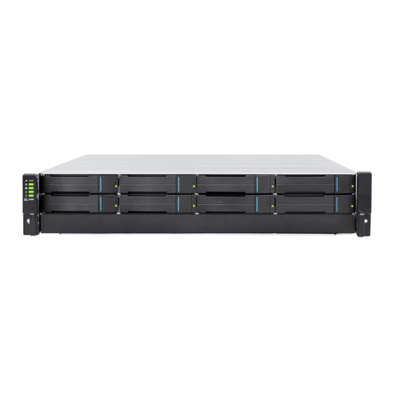
Chassis The chassis is rugged constructed and divided into front and rear sections. The chassis is designed to be installed into a rack or cabinet. Front Panel 1U model 2U model Hard drive trays (1): Each drive tray is hot-swappable and holds a 2.5 / 3.5-inch hard drive. -
Page 18: Rear Panel
Rear Panel Description Description Controller PSU + cooling module 1U model 2U model • Controllers (1): The controller module contains a main circuit board and a pre-installed DIMM module. For details, see Rear Panel Components. • PSU (2): The hot-swappable PSUs provide power to the system. There is a cooling module within each PSU. -
Page 19: Internal Backplane
Internal Backplane An integrated backplane separates the front and rear sections of the chassis. This circuit board provides logic level signals and low voltage power paths. Thermal sensors and I C devices are embedded to detect system temperatures and PSU/cooling module operating status. This board contains no user-serviceable components. -
Page 20: Front Panel Components
Front Panel Components LED Panel 1004 model: Designation Description Mute Service button Power supply status LED Cooling module status LED Temperature sensor status LED System fault LED 1008 model: Designation Description Service LED Power supply status LED Cooling module status LED Temperature sensor status LED System fault LED Mute Service button... -
Page 21: Drive Tray Bezel
Drive Tray Bezel The drive tray is designed to accommodate separately purchased SATA interface hard disk drives. There is a release button (1) that has to be used to retrieve disk drives from the chassis. To the right of the bezel plate, there is a drive busy LED (2) and a power status LED (3). -
Page 22: Rear Panel Components
Rear Panel Components System Controller Module Designation Description Designation Description Restore default button and LED USB2.0 service ports Controller status LEDs USB3.0 service ports Mini USB port (console port) iSCSI 1Gb ports WARNING The only time you should remove the controller is to install / replace the failed controller. -
Page 23: Psu & Cooling Module
PSU & Cooling Module The two redundant, hot-swappable PSUs have an extraction handle (1), cooling module (2), latch (3), PSU status LED (4) and a power socket (5). The cooling modules can operate at three rotation speed settings. Under normal operating conditions, the cooling fans run at the low speed. -
Page 24: System Monitoring Features
System Monitoring Features There are a number of monitoring approaches that provide the operating status of individual components. Main System Monitoring The system is aware of the status of components including those of: Controller (presence, voltage and thermal readings) ... - Page 25 WARNING Failing to respond when an audible alarm is heard can lead to permanent damage(s) to the system. When an audible alarm is heard, rectify the problem as soon as possible.
-
Page 26: Hot-Swapping
Hot-swapping The system comes with a number of hot-swappable components that can be exchanged while the system is still online without affecting the operational integrity. These components should only be removed from the system when they have to be replaced. The following components can be user-maintained and hot-swappable: ... -
Page 27: Hardware Installation
Hardware Installation This chapter describes how to install modular components, such as hard drives into the enclosure. NOTE Installation into a rack or cabinet should occur BEFORE hard drives are installed into the system. Installation Prerequisites Static-free installation environment: The system must be installed in a static-free environment to minimize the possibility of electrostatic discharge (ESD) damage. -
Page 28: Installation Procedures Overview
Installation Procedures Overview Following all the instructions provided below can minimize system installation time. Detailed, illustrated instructions for each component are given in the following sections. 1. Unpack: Unpack the system and confirm all components have been received against the Unpacking List. 2. -
Page 29: Unpacking The System
Unpacking the System Compare the Unpacking List included in the shipping package against the actual package contents to confirm that all required materials have arrived. Box contents For detail content(s), please refer to the unpacking list that came with the system. The accessory items include a serial port cable, screws, Quick Installation Guide, a CD containing the Management Software and its manual and Firmware Operation Manual, and a product utility CD containing the Installation and Hardware... -
Page 30: Installing Hard Drives
Installing Hard Drives Installation of hard drives should only occur after the enclosure has been placed well. Hard Drive Installation Prerequisites Hard drives are separately purchased and when purchasing hard drives, the following factors should be considered: Capacity (MB/GB): Use drives with the same capacity. RAID arrays use a “least-common-denominator”... -
Page 31: Hard Drive Designation
Hard Drive Designation Illustrations shown below are system hard drive slot number designations. Please familiarize yourself with the designations to avoid withdrawing the hard drive(s) out of the enclosure. 1U systems 2U systems... -
Page 32: Installing The Hard Drive Into Drive Tray
Installing the Hard Drive into Drive Tray Open the bezel by pressing the release button and gently pull out the tray. Place the hard drive into the drive tray, making sure that the interface connector is facing the open side of the drive tray and its label side facing up. Installing a 3.5”... -
Page 33: Installing The Hard Drive Tray Into The Enclosure
Installing the Hard Drive Tray into the Enclosure Once the hard drives have been installed in the drive trays, install the drive trays into the system. WARNING Each drive bay must be populated with a tray even if it does not contain a hard drive. An empty bay will disrupt ventilation and the system might overheat. -
Page 34: Installing The Controller
Installing the Controller After completing the battery backup unit and flash backup module installation, the controller can be re-inserted into the enclosure: 1. Insert the controller slowly into the module slot. When you feel the contact resistance, use slightly more force and then push both of the ejection levers upwards (indicated by the blue arrows) to secure the controller into chassis. -
Page 35: System Connection
System Connection This chapter outlines the general configuration rules you should follow when cabling a storage system. A complete description of the power-on and power-off procedures is also given in this chapter. General Considerations on Making Connections When selecting the number of hard drives to be included in a logical drive, the host channel bandwidth and the mechanical performance of individual disk drives should be considered. -
Page 36: Management Console Connections
Management Console Connections Designation Description Designation Description Serial port (for Telnet access) Local area network DB9 to mini USB EonOne / telnet console CAT5e LAN cable Connecting the system to external consoles Serial port (mini USB): Use the cable supplied with the system to connect to mini USB port. -
Page 37: Power Connections
Power Connections Once all hard drives have been properly installed and the I/O ports or management interfaces have been connected, the system can be powered on. Checklist BEFORE powering on the system, please check the following: Hard drives: Hard drives are correctly installed in the drive trays. ... -
Page 38: Power On Procedure
Power on Procedure To power on the system please follow the procedures below. 1. Turn on the power switches to the “on” position for every PSU (shown in blue). 2. Power on the networking devices, e.g. switches. 3. Power on the host computers. They should be the last devices to be turned on. 1U model 2U model NOTE... -
Page 39: Power On Status Check
Power on Status Check As a general rule, once the system has been powered on, there should be NO LED(s) that light up amber nor should you hear an audible alarm from the system. You may verify system status via the following monitoring interfaces: LEDs on rear chassis, including controller module, PSUs, and cooling modules (refer to System Monitoring). -
Page 40: Power Off Procedure
Power off Procedure If you wish to power down the system, please follow these steps: NOTE If you wish to power down the system, please ensure that no time-consuming processes, like “Regenerate Logical Drive Parity” or a “Media Scan,” are taking place. -
Page 41: System Monitoring
System Monitoring This system is equipped with a variety of self-monitoring features that help keep system managers aware of system operation statuses. Monitoring Features You may monitor the system through the following features: Firmware: The controller in the system is managed by a pre-installed firmware, which is accessible in a terminal program via the serial port. -
Page 42: Led Panel
LED Panel When lid amber to indicate failure, please check the corresponding module(s). For example, if the Thermal LED lights up amber, please check if there are faults on the system cooling modules (built within the PSU). 1004 model: Name Color Status 1. - Page 43 1008 model: Name Color Status White indicates that the system is being serviced or is requiring services. White Service OFF indicates that the system is not being serviced nor is requiring services. Green indicates that the system is powered properly. Green/ Power Amber...
-
Page 44: Drive Tray Led
Drive Tray LED Two LED indicators are located on the right side of each drive tray. When notified by a drive failure message, you should check the drive tray indicators to find the correct location of the failed drive. Name Color Status Flashing blue... -
Page 45: Controller Leds
Controller LEDs Name Color Status 1. Restore Lights up green after pressing and holding restore Green default button to indicate a successful reset. default Green indicates that a controller is operating healthily. Green/ Amber indicates that a component failure has 2. -
Page 46: Psu & Built-In Cooling Module Leds
PSU & Built-in Cooling Module LEDs The PSU (Power Supply Unit) contains the LEDs for the PSU and the cooling module statuses. When either of the unit fails, you need to replace the PSU as soon as possible. For details, please refer to Replacing the Power Supply Module. -
Page 47: Alarms And I2C Bus
Alarms and I2C Bus Other monitoring schemes include audible alarms and I C bus. Audible Alarms If any of the following components fails, the audible alarm will be triggered: Cooling fan modules PSU modules Hard disk drives ... -
Page 48: System Maintenance
System Maintenance WARNING Do not remove a failed component from the system until you have a replacement on hand. If you remove a failed component without immediate replacement, it will disrupt the internal airflow. Qualified engineers who are familiar with the system should be the only ones who make component replacements. -
Page 49: Restoring Default System Settings
Restoring Default System Settings NOTE Restoring default settings is a last-resort function. All configurations, such as parameters and host LUN mappings, will be erased. You may need to restore default settings in the following cases: When the firmware update procedure requires it. ... -
Page 50: Replacing The Controller Module
Replacing the Controller Module WARNING Controller firmware MUST be identical for proper functionality. DO NOT mix controller modules from different models. Each controller has a unique ID which is applied to host port names. As the result, you may encounter SAN problems with identical port names on multiple systems. - Page 51 6. Insert the new controller module. Carefully push the controller until you feel the contact resistance when the board edge connectors are engaging the backplane. Push the ejection levers upward (indicated by the blue arrows) and fasten the retention screw on the ejection levers. 7.
-
Page 52: Replacing Memory Module(S)
Replacing Memory Module(s) The controller comes with pre-installed DRAM module(s). You may upgrade it or replace it when the original module malfunctions (shown as the “NVRAM failure” event in EonOne). If you have two modules installed, please identify correctly which one has failed before proceeding with the replacement procedure. -
Page 53: Replacing The Power Supply / Cooling Module
Replacing the Power Supply / Cooling Module The power supply units (PSU) are configured in a redundant configuration with each PSU housed in a robust steel canister. Detecting a Failed PSU If a PSU module fails, the system notifies you through the following indicators: ... -
Page 54: Replacing Power Supply Unit
Replacing Power Supply Unit A failed PSU should be replaced as soon as possible, but only when you have a replacement module in your hand. Contact your vendor for more details (refer to Contact Information). WARNING Although the system can operate with a failed PSU in a system, it is not recommended to run the system with a failed PSU for an extended period of time. - Page 55 contact resistance, push the PSU module and it should engage the back-end connectors. 4. Reconnect the power cord. 5. Power on the PSU module. NOTE If a cooling fan failed within a PSU, the whole PSU module will need to be replaced.
-
Page 56: Replacing A Hard Drive
Replacing a Hard Drive WARNING Keep a replacement on hand before replacing the hard drive. Do not leave the drive tray open for an extended period of time or the internal airflow will be disrupted. Handle the hard drives with extreme care. Carry them only by the edges and avoid touching their circuits part and interface connectors. - Page 57 5. Replace the drive. After swapping the drive, fasten the retention screws back. Refer to screw locations in the previous step. 6. Insert the drive tray back into the enclosure. Install the drive tray with the front bezel open. When fully inserted, close the front bezel. 7.
-
Page 58: Appendix
Appendix Technical Specifications Power Supply Input Voltage Single-Controller model: 100VAC @ 10A 240VAC @ 5A with PFC (auto-switching) Frequency 50 to 60Hz Power rating 460W DC Output 12.0V: 38A (Max.) 5.0VSB: 2A (Max.) Input Frequency 50 to 60Hz AC Input 100VAC @ 10A or 240VAC @ 5A with PFC Power Factor Correction Hold-up Time... -
Page 59: Dimensions
Dimensions 1U series Dimensions Without chassis ears & protrusions Height 43.5mm Width 447mm Length 450mm 2U series Dimensions Without chassis ears & protrusions Height 159.3mm Width 449mm Length 450mm Environment 5 to 95% (non condensing – operating and non-operating) Humidity Operating: 5º... -
Page 60: Certifications
Certifications Summary Safety UL 60950-1, 2nd Edition BSMI CNS 14336-1: 99 年版 CB IEC 60950-1:2005 (Second Edition) + Am 1:2009 + Am 2:2013 EAC TP TC 004/2011, TP TC 020/2011 CE EN 55032:2012 +AC:2013 / EN61000-3-2:2014 / EN 61000-3-3: 2013 / EN 55024:2010+A1:2015 BSMI (CNS 13438) FCC (FCC Part 15,subpart B ) IEC 60068-2...
Need help?
Do you have a question about the EonStor GSe Pro 1000 Series and is the answer not in the manual?
Questions and answers