Table of Contents
Advertisement
Quick Links
Advertisement
Table of Contents

Subscribe to Our Youtube Channel
Related Manuals for Infortrend EonStor DS S48 Series


Summary of Contents for Infortrend EonStor DS S48 Series
- Page 1 Infortrend Hardware Manual EonStor DS S48 Series Version 1.6...
-
Page 2: Contact Information
1 Cherrywood, Stag Oak Lane Chineham Business Park Basingstoke, Hampshire RG24 8WF, UK Tel: +44-1256-707-700 Fax: +44-1256-707-889 Email, Technical Support, Website Germany/ Infortrend Deutschland GmbH Wappenhalle Business Center Konrad-Zuse-Platz 8, 81829 Munich, Germany Tel: +49-89-2070-42650 Fax: +49-89-2070-42654 Email, Technical Support,... -
Page 3: Copyright Notice
Infortrend, the Infortrend logo, SANWatch, ESVA, EonStor, EonStor DS, Trademarks EonNAS, and EonPath are registered trademarks of Infortrend Technology, Inc. Other names prefixed with “IFT” and “ES” are trademarks of Infortrend Technology, Inc. Windows is a registered trademark of Microsoft Corporation. -
Page 4: Safety Precautions
Safety Precautions Safety Precautions Read these instructions carefully before you install, operate, or transport the EonStor DS RAID systems and JBODs. Installation and Operation Install the rack cabinet and the associated equipment at a site where the ambient temperature stays lower than 35C. ... -
Page 5: Service And Maintenance
The use of Infortrend certified components is strongly recommended to ensure compatibility, quality and normal operation with your Infortrend products. Please contact your distributor for a list of Infortrend certified components (eg. SFP, SFP+, HBA card, iSCSI cable, FC cable, DRAM module, etc.). -
Page 6: Esd Precautions
ESD Precautions ESD Precautions Handle modules by their retention screws, ejector levers, or the module’s metal frame/ faceplate only. Avoid touching the PCB boards or connector pins. Use a grounded wrist strap and an anti-static work pad to discharge static electricity when installing or operating the enclosure. -
Page 7: About This Manual
About This Manual About This Manual This manual introduces EonStor DS S48 series RAID and JBOD storage expansion systems and the procedures on how to install, monitor, and maintain them. For the following subjects, consult other resources for more information: ... -
Page 8: Table Of Contents
Table of Contents Table of Contents Contact Information ....................... 2 Copyright Notice ........................3 Safety Precautions......................... 4 About This Manual ......................... 7 Table of Contents ........................8 Introduction Product Overview ..................... 11 1.1.1 Front Panel ....................... 12 1.1.2 Rear Panel ......................13 Major Components .................... - Page 9 Table of Contents 3.2.1 Fibre-Host Port....................48 3.2.2 Fibre-Host Topologies ..................48 3.2.3 Fibre Cabling..................... 49 3.2.4 Simple End-to-End Connection................. 51 3.2.5 DAS (Direct-Attached) Connection ..............52 3.2.6 Switched Fabric Connection (Dual-Controller) ..........54 3.2.7 Switched Fabric Connection (Single-Controller) ..........56 Hybrid Host Connections ..................
- Page 10 Table of Contents 5.7.3 Enclosure Replacement Procedure ..............117 Appendix Technical Specifications ..................119 6.1.1 Host/Drive Interface ..................119 6.1.2 RAID Configurations for RAID Models ............119 6.1.3 Fault Tolerance for RAID models ..............120 6.1.4 Power Supply....................121 6.1.5 Dimensions .....................
-
Page 11: Introduction
EonStor DS S48 Series Hardware Manual 1 Introduction Product Overview This manual introduces the EonStor DS S48 series RAID and JBOD storage systems that support SAS 3Gbps, SAS 6Gbps, SATA-II 3Gbps and SATA-III 6Gbps hard drives up to 3TB (refer to Installing Hard Drive Prerequisites). -
Page 12: Front Panel
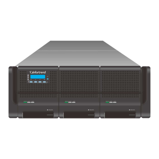
1.1.1 Front Panel The Infortrend S48 series enclosure front panel features three drawers that hold 16 hard drives each. Looking at the front panel, the S48 RAID and JBOD systems can be distinguished from the LCD panel (1) that can be found on the front panel of the RAID series enclosures. -
Page 13: Rear Panel
EonStor DS S48 Series Hardware Manual 1.1.2 Rear Panel The rear panel of S48 series comprises of (1) controller A & (2) controller B (or a (4) dummy cage for single controller models) and (3) three power supplies with built-in system cooling modules. -
Page 14: Major Components
EonStor DS S48 Series Hardware Manual Major Components NOTE On receiving and unpacking your system, check the package contents against the included Unpacking List. If any modules, contents or accessories are missing, contact your system vendor immediately. 1.2.1 Cache Backup Module (CBM) of RAID Controllers... -
Page 15: Jbod Controller And Interface
EonStor DS S48 Series Hardware Manual The use of a CBM is highly recommended in order to safeguard data integrity. If you are using the single controller models and would like to install a CBM, refer to Installing Cache Backup Module (CBM) for RAID Models. -
Page 16: Power Supply Unit (Psu) W/ Built-In Cooling Module & Drawer Fan Module
EonStor DS S48 Series Hardware Manual 1.2.3 Power Supply Unit (PSU) w/ Built-in Cooling Module & Drawer Fan Module There are three PSUs with built-in cooling modules to supply power to the S48 and cool the system. Each power supply contains the following fans:... -
Page 17: Front Panel Components
EonStor DS S48 Series Hardware Manual Front Panel Components The modular design of the active components facilitates their easy installation and removal. Hot-swap mechanisms are incorporated to eliminate power surges and signal glitches that might occur while removing or installing these modules. Each component is described below. -
Page 18: Led Panel For Jbod Models
EonStor DS S48 Series Hardware Manual 1.3.2 LED Panel for JBOD Models The LED panel on a JBOD storage expansion system can be located on the chassis ear. The LED panel contains Service/ Mute LED & button (1), a power supply status LED (2), cooling module status LED (3), temperature sensor status LED (4), System fault LED (5) and rotary ID switch (6). -
Page 19: Hard Drive Drawer
EonStor DS S48 Series Hardware Manual 1.3.3 Hard Drive Drawer Drawer fan module Dri ve Sl ot that Make sure 9 13 17 21 25 29 33 37 41 45 handles on the disk drives 6 10 14 18 22 26 30... - Page 20 EonStor DS S48 Series Hardware Manual Front of enclosure Opening the drawer There are three hard drive drawers in the S48 system and when viewed from the top, the first drawer on the left contains hard drives numbering from 1~16, the second drawer in the middle contains hard drives 17~32 and the third drawer on the right contains hard drives 33~48.
-
Page 21: Controller Interfaces
EonStor DS S48 Series Hardware Manual Controller Interfaces The RAID system’s controller features interfaces including host ports, Ethernet management port, serial port and a SAS expansion port. The JBOD system’s controller features two SAS ports to daisy chain a RAID system and other JBODs. -
Page 22: S48 Jbod
EonStor DS S48 Series Hardware Manual included in the package. For single-controller models, the serial cable is user-supplied. 4. iSCSI host ports: The S48F-G/R2842-6 RAID system utilizes a hybrid controller that combines Fibre and iSCSI connection to offer users greater versatility. -
Page 23: Power Supply Unit (Psu)
EonStor DS S48 Series Hardware Manual Power Supply Unit (PSU) The system is equipped with three redundant, hot-swappable, 530W PSUs at the rear section of the chassis. Each PSU comes with a (1) power socket and built-in (2) cooling modules to provide sufficient airflow. -
Page 24: Drawer Fan Cooling Module
EonStor DS S48 Series Hardware Manual Drawer Fan Cooling Module Situated at the end of each drawer, there is a drawer fan module at the end of each drawer. They serve to pull air in from through the convection holes on the front panel, the air cools... -
Page 25: System Monitoring Features
EonStor DS S48 Series Hardware Manual System Monitoring Features There are a number of monitoring approaches that provide the operating status of individual components. 1.7.1 Expansion Enclosure Support Monitoring: A managing RAID system is aware of the status of JBOD components including those of: ... -
Page 26: I 2 C Bus
EonStor DS S48 Series Hardware Manual JBOD Enclosure Status Monitoring: A RAID system, when connected with expansion JBODs, acquires the component status within other enclosures via a proprietary enclosure monitoring service using the in-band connectivity. No additional management connection is required. -
Page 27: Hot-Swapping
EonStor DS S48 Series Hardware Manual Hot-swapping The system comes with a number of hot-swappable components that can be exchanged while the system is still online without affecting the operational integrity. These components should only be removed from the system when they are being replaced. -
Page 28: Hardware Installation
EonStor DS S48 Series Hardware Manual 2 Hardware Installation This chapter describes how to install modular components, such as hard drives and CBM, into the chassis. Please crosscheck with the unpacking list to ensure you have received all components. NOTE The system enclosure MUST be installed into a rack or cabinet BEFORE hard drives are installed into the system. -
Page 29: Installation Procedures Overview
EonStor DS S48 Series Hardware Manual DRAM modules: If you wish to change the pre-installed DRAM module, you can find DRAM module replacement procedures in Replacing the DRAM module for RAID Models. CBM: If you wish to install Cache Backup Module (Battery Backup Unit and/or Flash Backup Module), the CBM should be installed prior to powering on the system. - Page 30 EonStor DS S48 Series Hardware Manual drives along with the system, brackets will be pre-installed onto the hard drive(s) for you while the brackets included in the accessory box will act as spares. 5. Install hard drive: After the hard drives brackets have been installed onto the hard drives, you can install it into the enclosure itself (only install hard drives AFTER the enclosure has been rack mounted onto the rack).
-
Page 31: Unpacking The System
EonStor DS S48 Series Hardware Manual Unpacking the System Compare the Unpacking List included in the shipping package against the actual package contents to confirm that all required materials have arrived. 2.3.1 Box contents Upper level box contents: The box on the upper level contains 48 sets of hard drive brackets, power cords and accessories. -
Page 32: Adjuster Pillars
EonStor DS S48 Series Hardware Manual Adjuster Pillars Adjuster Pillar Pack Contents Quanti Item Description 25mm (1 inch) adjuster pillar (left & right) 50mm (2 inch) adjuster pillar (left & right) screws Cage nut Due to the length of S48 enclosures and depending on the position where your front rack posts (1) are secured on the chassis guide (2), you may need to install adjuster pillars so the rear end of S48 will not protrude out of the rear end of the cabinet. - Page 33 EonStor DS S48 Series Hardware Manual Position A: You do not need to install adjuster pillars. Position B: You need to install the 25mm adjuster pillars. Position C: You need to install the 50mm adjuster pillars. The rack post installation positions shown conform to the rack-mount server chassis...
-
Page 34: Adjuster Pillar Installation
EonStor DS S48 Series Hardware Manual 2.4.1 Adjuster Pillar Installation The adjuster pillars (R-right / L-left) are secured at the 2U / 3U position on the rack post (indicated by the blue circles). M5 cage nuts (indicated by the blue arrows) are... -
Page 35: Installing The Enclosure (Rack-Mounting)
EonStor DS S48 Series Hardware Manual Installing the enclosure (Rack-mounting) WARNING DO NOT insert hard drive(s) into the enclosure before it is installed into the rack otherwise the enclosure will become too heavy. 2.5.1 Slide Rail Contents Quanti Item Description... -
Page 36: Slide Rail Installation Procedure
EonStor DS S48 Series Hardware Manual 2.5.2 Slide Rail Installation Procedure 1. To separate the enclosure slide rail (1) from the rack slide rail (2), you must fully extend the slide rail, press down on the release lever (indicated by the blue arrow) on the side and pull the enclosure slide rail apart from the enclosure rack slide rail. - Page 37 EonStor DS S48 Series Hardware Manual 3. To attach the rack slide rail bracket (3) and rack slide rail (2) onto the front and rear posts of the rack, adjust the bracket positions and fasten the eight M4 x 6mm retention screws (6) (4 screws on each bracket) to secure the brackets.
- Page 38 EonStor DS S48 Series Hardware Manual 5. To insert the enclosure into the rack, with at least three people lifting the enclosure, align the end of the enclosure slide rail to the opening of the rack slide rail and gently insert it into the rack. You should hear a “click” sound when the enclosure slide rail engages the rack slide rail at the release lever.
- Page 39 EonStor DS S48 Series Hardware Manual 7. Secure the system enclosure onto the rack post by opening the side chassis ears to expose the screw-holes, secure using two 20mm screws and cage nuts from the accessory box as shown in the illustration below.
-
Page 40: Installing Hard Drives
EonStor DS S48 Series Hardware Manual Installing Hard Drives 2.6.1 Installing Hard Drive Prerequisites Hard drives are separately purchased and please consider the following when purchasing hard drives: Capacity (MB/GB): RAID arrays use a “least-common-denominator” approach, meaning the maximum capacity used in each drive to compose a RAID array is the maximum capacity of the smallest drive. -
Page 41: Installing Hard Drive Brackets
EonStor DS S48 Series Hardware Manual 2.6.2 Installing Hard Drive Brackets The hard drive bracket for the S48 series comes in three pieces. There is a (1) rail plate, (2) handle anchor plate and a (3) handle plate. The three pieces are designed to be attached to the non-connector end (opposing side to the connector). -
Page 42: Installing Hard Drives Into The Drawer
EonStor DS S48 Series Hardware Manual 2.6.3 Installing Hard Drives into the Drawer Once the hard drive brackets have been installed onto hard drives that are to be installed into the drawer, open the drawer 1 (situated on the left) insert each hard drive vertically (in a specific order) while hooking the bracket handle with your index finger. -
Page 43: System Connection
EonStor DS S48 Series Hardware Manual 3 System Connection This chapter outlines some general configuration rules you should follow when cabling a storage system and introduces basic information about topologies. You can use these topologies or refer to them as a guide for developing your own unique topologies. -
Page 44: Host-Side Topologies
EonStor DS S48 Series Hardware Manual it is preferred that all the disk drives within a chassis have the same capacity. Tiered storage configuration is supported, e.g., 150GB SAS drives in your RAID enclosure and 750GB SATA drives in JBODs. -
Page 45: Maximum Concurrent Host Lun Connection ("Nexus" In Scsi)
EonStor DS S48 Series Hardware Manual 3.1.3 Maximum Concurrent Host LUN Connection (“Nexus” in SCSI) The "Max Number of Concurrent Host-LUN Connection" menu option is used to set the maximum number of concurrent host-LUN connections. Change this menu option setting only if you have more than four logical drives or partitions. Increasing this number might increase your performance. -
Page 46: Maximum Queued I/O Count
EonStor DS S48 Series Hardware Manual 3.1.4 Maximum Queued I/O Count The "Maximum Queued I/O Count" menu option enables you to configure the maximum number of I/O operations per host channel that can be accepted from servers. The predefined range is from 1 to 1024 I/O operations per host channel, or you can choose the "Auto"... -
Page 47: Fibre-Host Raid Connections
Optical cables are also less susceptible to EMI. The following transceiver and cables have been tested and proven to be compatible with your systems. Infortrend’s part numbers for cables of different lengths are: IFT-9370CSFP8GA AFBR-57D5APZ, Fibre Channel 8.5/ 4.25 / 2.125 GBd... -
Page 48: Fibre-Host Port
FC performance and reliability specifications. WARNING The SFP transceiver from Infortrend contains a laser diode featuring class 1 laser. To ensure continued safety, do not remove any covers or attempt to gain access to the inside of the product. -
Page 49: Fibre Cabling
EonStor DS S48 Series Hardware Manual This topology allows many devices to communicate at the same time. A Fibre switch is required to implement this topology. NOTE If a logical drive can be accessed by different servers, file locking, FC switch zoning, port binding, and multi-pathing access control will be necessary. - Page 50 EonStor DS S48 Series Hardware Manual 6. Remove the (4) protective caps from the LC-to-LC type cable. Save the protective caps for future use. 7. Carefully insert the cable into an SFP module that is already on the system. The cable connector is keyed and will click into place.
-
Page 51: Simple End-To-End Connection
EonStor DS S48 Series Hardware Manual 3.2.4 Simple End-to-End Connection HBA 0 HBA 0 HBA 1 HBA 1 EonPath EonPath CH0 B113 CH2 A112 CH2 B113 CH0 A112 CH3 A112 CH3 B113 CH1 B113 CH1 A112 CH2 A112 CH2 B113... -
Page 52: Das (Direct-Attached) Connection
EonStor DS S48 Series Hardware Manual 3.2.5 DAS (Direct-Attached) Connection NOTE If a logical drive can be accessed by different servers, file locking, FC switch zoning, port binding, and multi-pathing access control will be necessary in order to avoid access contention. - Page 53 EonStor DS S48 Series Hardware Manual With more disk drives over the SAS expansion links, you can create more logical groups of drives. Avail these logical drives using more host channel IDs or LUN numbers. If a server has multiple data paths to a RAID system, a multi-path software is necessary, e.g., EonPath driver.
-
Page 54: Switched Fabric Connection (Dual-Controller)
EonStor DS S48 Series Hardware Manual 3.2.6 Switched Fabric Connection (Dual-Controller) NOTE A logical partition presented through LUN Mapping can be seen by all servers across SAN. Make sure you have access control such as file-locking, switch zoning, port binding, etc., to avoid access contention. - Page 55 EonStor DS S48 Series Hardware Manual Channel link bypass is provided on external FC switches. Each of the application servers shown in the diagram is equipped with two HBAs with FC links via two FC switches to the SFP ports on individual RAID controllers.
-
Page 56: Switched Fabric Connection (Single-Controller)
EonStor DS S48 Series Hardware Manual 3.2.7 Switched Fabric Connection (Single-Controller) HBA 0 HBA 1 HBA 0 HBA 1 EonPath EonPath CH0 B114 CH1 B114 CH0 A112 CH1 A112 CH0 B113 CH1 B113 CH0 A115 CH1 A115 10 x 7 8 9 1 011 1 2... - Page 57 EonStor DS S48 Series Hardware Manual Shown on previous page is a sample drawing showing connections with each SFP port connected to FC switches and then to host adapters. See logical associations in the drawing for LUN mapping details. Use Enclosure-specific spares to prevent a spare drive from participating in the rebuild of a logical drive on another enclosure.
-
Page 58: Hybrid Host Connections
EonStor DS S48 Series Hardware Manual Hybrid Host Connections For hybrid systems that feature two additional iSCSI ports, they can be used for remote replication or be used for host LUN mapping if users wish to do so. 3.3.1 Single Hybrid Unit Connected to FC/iSCSI Hosts... -
Page 59: Utilizing Hybrid Iscsi Ports For Data Replication
EonStor DS S48 Series Hardware Manual 3.3.2 Utilizing Hybrid iSCSI ports for Data Replication HBA 0 HBA 0 HBA 0 HBA 0 HBA 1 HBA 1 HBA 1 HBA 1 EonPath EonPath EonPath EonPath FC #1 FC #2 iSCSI #1... -
Page 60: Jbod Connections
EonStor DS S48 Series Hardware Manual JBOD Connections A 50cm SFF-8088 to SFF-8088 host link cable is included per S48S JBOD purchased. Please contact your vendor if you need to purchase other cable types or if you need cable(s) of different lengths. Shown below are some details of the... -
Page 61: Expansion Links
EonStor DS S48 Series Hardware Manual 3.4.1 Expansion Links There are two principles with the combinations of RAID and JBOD: Dual-controller RAID connects dual-controller JBODs; Single-controller RAID connects to single-controller JBODs. An alternate IFT-9270CMSASCAB6, SFF-8088 to SFF-8088 170cm cable is available for making expansion links with a dual-controller configuration. - Page 62 EonStor DS S48 Series Hardware Manual firmware automatically manages these addresses. Please use a flat blade screwdriver to manually configure the rotary ID switch (refer to LED Panel for JBOD models).
-
Page 63: Configuration Rules
JBOD controller A To another JBOD JBOD controller B SAS hard drives feature dual port fault-tolerant links (the dual port fault-tolerant capability is only viable in dual controller models). SAS expansion cables will be available with Infortrend’s JBODs. Note... - Page 64 EonStor DS S48 Series Hardware Manual that if many JBODs are connected, a longer SAS external cable (e.g., a 120cm or 170cm cable; refer to JBOD Connections) may be necessary for connecting a JBOD from the opposite direction offering high redundancy.
-
Page 65: Sas Expansion Configuration
EonStor DS S48 Series Hardware Manual SAS Expansion Configuration NOTE S48 4U JBODs must be connected at the end of the daisy chain. If a S48 4U JBOD is the first JBOD connected in the chain, it is recommended to expand ONLY using S48 4U JBODs. -
Page 66: S12F-G/R2850 Raid, 2U Jbod And S48 Jbod
EonStor DS S48 Series Hardware Manual 3.5.2 S12F-G/R2850 RAID, 2U JBOD and S48 JBOD Dual-Controller Single-Controller RAID RAID ID-1 ID-1 ID-2 ID-2 ID-3 ID-3 ID-4 ID-4 ID-5 ID-5 ID-6 ID-6 ID-9 ID-9 ID-12 ID-12... -
Page 67: S16F-G/R2850 Raid, 3U Jbod And S48 Jbod
EonStor DS S48 Series Hardware Manual 3.5.3 S16F-G/R2850 RAID, 3U JBOD and S48 JBOD Dual-Controller Single-Controller RAID RAID ID-1 ID-1 ID-2 ID-2 ID-3 ID-3 ID-4 ID-4 ID-5 ID-5 ID-6 ID-6 ID-9 ID-9 ID-12 ID-12... -
Page 68: S24F-G/R2850 Raid, 3U Jbod And S48 Jbod
EonStor DS S48 Series Hardware Manual 3.5.4 S24F-G/R2850 RAID, 3U JBOD and S48 JBOD Dual-Controller Single-Controller C H 0 C H 1 C H 2 C H 3 C H 0 C H 1 C H 2 C H 3... -
Page 69: Management Console Connections
EonStor DS S48 Series Hardware Manual Management Console Connections Dual controller management Single controller management connection connection You will need the following cables to connect the RAID system to external consoles. Serial port: For dual-controller models, a (1) DB9 males to 1 female serial Y-cable is provided to connect to the (2) management console. -
Page 70: Power Connections
EonStor DS S48 Series Hardware Manual Power Connections Once all of the disk drives have been properly installed and the I/O ports or management interfaces have been connected, the system can be powered on. Checklist BEFORE powering on the system, please check the following: ... -
Page 71: Connecting Power Cords
EonStor DS S48 Series Hardware Manual 3.7.1 Connecting Power Cords Use the included cable clamps to secure power cord connections. 1. Remove power cords and cable clamps from the accessory boxes. 2. Combine cable strap with cable clamp. 3. Attach cable clamps to the power cords by opening and enwrapping the... - Page 72 EonStor DS S48 Series Hardware Manual 4. Adjust the position of cable straps using the release tab. 5. Adjust the position so that when a power plug is connected, the barb anchor can be inserted into the anchor hole above the power socket (indicated by...
-
Page 73: Power On Procedures
EonStor DS S48 Series Hardware Manual 3.7.2 Power On Procedures When powering on the system, please follow these steps: Power on expansion JBODs. If a multi-enclosure configuration is applied, Step 1. power on the expansion enclosures. Power on the RAID system. -
Page 74: Power On Status Check
EonStor DS S48 Series Hardware Manual 3.7.3 Power On Status Check As a general rule, once the system has been powered on, there should NOT be LED(s) that light up nor should you hear an audible alarm from the amber system. -
Page 75: Lcd Screen
EonStor DS S48 Series Hardware Manual 3.7.4 LCD Screen When powering on the RAID system, wait for the front panel LCD screen to show “READY” or “No Host LUN.” The LCD screen startup sequence is shown and described in the sequence below: Initializing…... -
Page 76: Power Off Procedure
EonStor DS S48 Series Hardware Manual 3.7.5 Power Off Procedure If you wish to power down the system, please follow these steps: NOTE If you wish to power down the system, please ensure that no time-consuming processes, like “Regenerate Logical Drive Parity” or a “Media Scan,” are taking place. - Page 77 EonStor DS S48 Series Hardware Manual 4. Turn off the power. Power off the system by flipping the chief power switch to the off position. Once the system has powered down, other devices/ enclosures that are connected to the system can be subsequently powered down.
-
Page 78: System Monitoring
EonStor DS S48 Series Hardware Manual 4 System Monitoring The EonStor DS series is equipped with a variety of self-monitoring features that help keep system managers aware of system operation statuses. Monitoring Features You may monitor the system through the following features: ... - Page 79 EonStor DS S48 Series Hardware Manual SANWatch: SANWatch is a Java-based Graphical User Interface (GUI) that can to monitor and manage the system locally or remotely over TCP/IP network, via the Ethernet Management port. The management session is conducted using the Ethernet management port. For more details, see the SANWatch manual in the CD-ROM.
- Page 80 EonStor DS S48 Series Hardware Manual LEDs: LED indicators notify users of system status, events, and failures. LEDs are located on both the front and rear panel of the chassis. For details, see and subsequent sections. Audible alarm: Audible alarm will be triggered in case of system failures.
-
Page 81: Front Panel
EonStor DS S48 Series Hardware Manual Front Panel 4.2.1 LCD Keypad for RAID Models Keypad Buttons The LCD keypad on RAID systems consists of five buttons, three LEDs, and a 16x2-character LCD screen that provides access to firmware-embedded utilities. Here are the definitions of the buttons and an example of the menu and sub-menus is shown on the next page. - Page 82 EonStor DS S48 Series Hardware Manual LCD panel menu and sub-menu To enter the sub-menus from the ready screen, press and hold the “Ent” button for 2 seconds. Once you’re in the sub-menus, press and up and down key (indicated by...
-
Page 83: Led Definitions For Raid Systems
EonStor DS S48 Series Hardware Manual 4.2.2 LED Definitions for RAID Systems Keypad LED definitions Name Color Status indicates that power is supplied to the Blue system, and system state is normal. 1. PWR Blue (Power) OFF indicates that no power is supplied to the system or the RAID controller has failed. -
Page 84: Led Panel For Jbod Models
EonStor DS S48 Series Hardware Manual 4.2.3 LED Panel for JBOD Models Name Color Status indicates that the system is being White serviced or is requiring services. OFF indicates that the system is not being serviced nor is requiring services. - Page 85 EonStor DS S48 Series Hardware Manual properly. Amber indicates that there is a power failure Amber in the system. indicates that the cooling fan is Green operating properly. Green/ 3. Cooling fan Amber indicates that the there is a cooling Amber fan failure in the system.
-
Page 86: Drawer & Drawer Fan Led
EonStor DS S48 Series Hardware Manual 4.2.4 Drawer & Drawer Fan LED Three LED indicators are located on the right side of the front panel of each drawer. Their definitions are as below: Name Color Status indicates the drawer is full with hard drives. -
Page 87: Hard Drive Failure Led
EonStor DS S48 Series Hardware Manual 4.2.5 Hard Drive Failure LED There is a dedicated LED for every hard drive location in the drawers. As show in the blue circles below, each LED is accompanied by a triangle indicator to let users know the lid LED refers to which hard drive in the drawer. -
Page 88: Controller Leds
EonStor DS S48 Series Hardware Manual Controller LEDs 4.3.1 Controller LED for RAID Models Designation Color Status indicates that a RAID controller is operating Green healthily. Green/ indicates that a component failure has Amber 1. Ctrl Status Amber occurred, or inappropriate RAID configurations have caused system faults. - Page 89 EonStor DS S48 Series Hardware Manual battery backup unit is capable of sustaining memory in case of power loss. Blinking indicates cached data is being transferred to the flash module after the occurrence of a power outage. Once the transfer is done, all LEDs will turn off.
-
Page 90: Ethernet Management Port Leds For Raid Models
EonStor DS S48 Series Hardware Manual 4.3.2 Ethernet Management Port LEDs for RAID Models One Ethernet management port is located on each controller’s faceplate. Two LEDs indicate Ethernet connection speed and link status. Designation Color Status indicates active data Blinking green 1. -
Page 91: Raid Fibre Host Port Leds
EonStor DS S48 Series Hardware Manual 4.3.3 RAID Fibre Host Port LEDs The FC host ports have two LEDs displaying their operating status. Designation Color Status indicates 8Gbps connection. Green Green indicates 4Gbps connection. 1. 8/4/2G Amber Amber OFF indicates 2Gbps speed or no connection. -
Page 92: Raid Iscsi Host Port Leds
EonStor DS S48 Series Hardware Manual 4.3.4 RAID iSCSI Host Port LEDs Designation Color Status indicates currently connected with GbE Green speed. Green 1. Speed OFF means connected with 10/100 speed. indicates the port is linked. Green Green 2. Link Status indicates active transmission. -
Page 93: Controller Led For Jbod Models
EonStor DS S48 Series Hardware Manual 4.3.5 Controller LED for JBOD Models Designation Color Status indicates that the controller is operating Green healthily. Green 1. Ctrl Status indicates that a component failure has Amber Amber occurred. It is also lit during the initialization process. -
Page 94: Psu & Built-In Cooling Module Leds
EonStor DS S48 Series Hardware Manual PSU & Built-in Cooling Module LEDs The PSU (Power Supply Unit) contains LED indicators that indicate PSU statuses or the statuses for the built-in cooling modules. When any of the LEDs light up red, it indicates the unit has failed, you should contact your vendor and arrange for a replacement as soon as possible. -
Page 95: Alarms And I2C Bus
EonStor DS S48 Series Hardware Manual Alarms and I2C Bus Other monitoring schemes include audible alarms and I C bus. 4.5.1 Audible Alarms If any of the following components fails, the audible alarm will be triggered: Cooling fan modules ... -
Page 96: Restoring Default System Settings
EonStor DS S48 Series Hardware Manual Restoring Default System Settings NOTE Restoring default settings is a last-resort function. All configurations, such as parameters and host LUN mappings, will be erased. You may need to restore default settings in the following cases: ... - Page 97 EonStor DS S48 Series Hardware Manual iii. Remove Controller B (indicated by the blue circle shown below) from the chassis. Please refer to Replacing the Controller Module(s): Single / Dual / Simultaneous Upgrade. Controller A Controller B 2. Power off the RAID system.
- Page 98 EonStor DS S48 Series Hardware Manual options: 1. Use the “Restore NVRAM from Disks “or “ Restore NVRAM from Files” functions in the firmware. ID/LUN mapping will be restored. 2. Use the LCD panel to restore ID/LUN mapping settings (refer to the illustration below).
-
Page 99: Restoring Default Settings For Single-Controller Models
EonStor DS S48 Series Hardware Manual 4.6.2 Restoring Default Settings for Single-Controller Models To restore default settings for single-controller models, follow these steps. 1. Stop all host I/Os. 2. Save the current configuration by using the “Export NVRAM” function. Users... - Page 100 EonStor DS S48 Series Hardware Manual 6. When the “Restore Def.” LED (2) turns on and the “Default Restored” firmware event message appear on the LCD, you may release the Restore Default button (the system default has been restored). 7. To restore previous ID/LUN mapping settings, users may use the following options: 3.
-
Page 101: System Maintenance
EonStor DS S48 Series Hardware Manual 5 System Maintenance WARNING Do not remove a failed component from the system until you have a replacement on hand. If you remove a failed component without replacing it, the internal airflow will be disrupted. -
Page 102: Replacing The Controller Module(S)
EonStor DS S48 Series Hardware Manual Replacing the Controller Module(s) WARNING Do not mix controller modules from different models. Each controller has a unique ID which is applied to host port names. As the result, you may encounter SAN problems with identical port names on multiple systems. - Page 103 EonStor DS S48 Series Hardware Manual 4. (For single controller models or when replacing both controllers simultaneously) Power off the system. Turn off the power switches and unplug the power cords from both PSUs. 5. Disconnect all cables that are connected to the controller module.
- Page 104 EonStor DS S48 Series Hardware Manual 9. Push the ejection levers upward and fasten the retention screw on the ejection levers. 10. Reattach all the cables. 11. (For single controller models or when replacing both controllers simultaneously) Power up the system. Check system message on the LCD screen, SANWatch, or firmware menu-driven utility.
-
Page 105: Replacing / Upgrading The Dram Module For Raid Models
Follow the ESD Precautions (refer to Precautions). Contact Infortrend or your system vendor for selecting a compatible DRAM module. Reusing the DRAM module removed from a failed controller is not recommended unless you have a similar RAID system to test its integrity. - Page 106 EonStor DS S48 Series Hardware Manual 2. Remove the existing (1) DRAM module from the slot by pushing down the (6) clips on both ends. 3. To install the separately purchased DRAM module, simply match the notch at the bottom of the module to the corresponding slot notch. Firmly push the module down onto the slot until the clips on both sides latch on.
-
Page 107: Replacing / Upgrading The Cbm For Raid Models
EonStor DS S48 Series Hardware Manual Replacing / upgrading the CBM for RAID Models For single controller models, upgradeable components are listed below: Battery Backup Unit (BBU): In the event of a power failure, the BBU can help store/ save cached data in the DRAM module for up to 72 hours. -
Page 108: Replacing / Upgrading The Bbu
EonStor DS S48 Series Hardware Manual 5.3.1 Replacing / upgrading the BBU To replace the BBU, follow these steps: 1. Remove the controller module from the chassis (refer to Replacing Controller Module(s): Single / Dual / Simultaneous Upgrade). 2. Loosen the (1) BBU by turning the (2) captive screw anticlockwise and gently lift the BBU off the (3) connector end. -
Page 109: Replacing / Upgrading The Fbm
EonStor DS S48 Series Hardware Manual 5.3.2 Replacing / upgrading the FBM To replace the FBM, follow these steps: 1. Remove the controller module from the chassis (refer to Replacing Controller Module(s): Single / Dual / Simultaneous Upgrade). 2. Remove the (1) BBU module (see the previous section). -
Page 110: Replacing The Power Supply Module
EonStor DS S48 Series Hardware Manual Replacing the Power Supply Module The power supply modules (PSUs are fully redundant and each PSU module is housed in a robust steel canister. 5.4.1 Detecting a Failed PSU If a PSU fails, the system notifies you through the following indicators: ... -
Page 111: Replacing The Psu
EonStor DS S48 Series Hardware Manual 5.4.2 Replacing the PSU A failed PSU should be replaced as soon as possible, but only when you have a replacement module in your hand. Contact technical support for more details (refer to Customer Support). - Page 112 EonStor DS S48 Series Hardware Manual 4. Insert the replacement module. Make sure the (1) extraction handle is held at its highest position so that the saddle notches on the sides of the handle can snap onto the metal (2) anchor pins placed along the interior walls of the PSU slot.
-
Page 113: Replacing The Drawer Fan Module
EonStor DS S48 Series Hardware Manual Replacing the Drawer Fan Module WARNING Although the cooling modules are fully redundant, it is not advisable to run the system with only one or two drawer fan module for more than five minutes. -
Page 114: Replacing A Hard Drive
EonStor DS S48 Series Hardware Manual Replacing a Hard drive WARNING Keep a replacement on hand before replacing the hard drive. Do not leave the drive tray open for an extended period of time or the internal airflow will be disrupted. - Page 115 EonStor DS S48 Series Hardware Manual 3. There are hard drive dedicated LEDs to notify which hard drive(s) are faulty. 4. Replace the drive by pulling out a hard drive vertically while hooking your index finger around the bracket handle.
-
Page 116: Replacing The Enclosure
Apart from obvious damage (circuit exposure, extreme enclosure deformation, etc.), an indication of enclosure backplane failure can be determined by differential diagnosis. The simple differential diagnosis will also assist in Infortrend Technical Support staffs to promptly identify the issue! Differential diagnosis can be done by swapping two modules to test the backplane’s integrity. -
Page 117: Enclosure Replacement Must Knows
Technical Support Staff (refer to Customer Support). Step 3. Once confirmed with Infortrend’s Technical Support staff that it is a new enclosure you need, please order the exact same model’s enclosure (Important: same model enclosure backplane board will have the same embedded license number so it is essential for you to order the same model’s enclosure!). - Page 118 EonStor DS S48 Series Hardware Manual XML format (please refer to EonStor DS SANWatch User Manual section on Replacing System Configurations). If you choose to manually set all settings, you may skip this step. Step 5. Power off the system (refer to section...
-
Page 119: Appendix
EonStor DS S48 Series Hardware Manual 6 Appendix Technical Specifications 6.1.1 Host/Drive Interface Fibre/iSCSI Hybrid-host RAID models (S48F-R/G2842-6 series) Host O/S Compatibility Host O/S independent Host Interface 8Gbps Fibre Channel + RJ-45 Gigabit Ethernet 4 pre-configured Fibre host channels (per controller) +... -
Page 120: Fault Tolerance For Raid Models
EonStor DS S48 Series Hardware Manual Real-time Clock For event messages with time record and task scheduling Text-based firmware-embedded utility over RS-232C through the serial cable Telnet via an established network connection Configuration LCD keypad panel ... -
Page 121: Power Supply
EonStor DS S48 Series Hardware Manual Salvage the 1 Temporary Failed Drive in a RAID 0 Logical Drive 6.1.4 Power Supply Features Description Input Voltage 100VAC @ 10A 240VAC @ 5A with PFC (auto-switching) Frequency 47 to 63Hz DC Output 12.0V: 43A (Max.) -
Page 122: Environment
EonStor DS S48 Series Hardware Manual 6.1.6 Environment Condition Description Humidity 5 to 95% (non condensing – operating and non-operating) Operating: 0º to 35ºC Temperature Non-operating: -40º to 60ºC Operating: Sea level to 12,000ft Altitude Packaged: Sea level to 40,000ft... -
Page 123: 8Gbps Fc Port Pinouts
EonStor DS S48 Series Hardware Manual 6.2.1 8Gbps FC Port Pinouts Name Description Transmitter ground Transmitter fault indication – High indicates a fault condition FAULT Transmitter Disable – Module electrical input disables on high or open MOD_DEF(2) Module definition 2 – Two wire serial ID interface data line (SDA) MOD_DEF(1) Module definition 1 –... - Page 124 EonStor DS S48 Series Hardware Manual RX_LOS Indicates loss of signal; High indicates loss of received optical signal No Connect Internal pullup 30KΏ to Vcc Receiver Ground Receiver Ground Inverse Received DATA Out Received Data Out Receiver ground Receiver power +3.3V Transmitter power +3.3V...
-
Page 125: Gbe Ethernet Port Pinouts For Iscsi-Host Raid Models
EonStor DS S48 Series Hardware Manual 6.2.2 GbE Ethernet Port Pinouts for iSCSI-Host RAID Models Name Name BI_DA+ BI_DC- BI_DA- BI_DB- BI_DB+ BI_DD+ BI_DC+ BI_DD- NOTE Automatic MDI/MDI-X Crossover: Crossover can be implemented internally at hub or switch or externally through twisted pair media. -
Page 126: Db-9 Serial Port & Cable For Raid Models
EonStor DS S48 Series Hardware Manual 6.2.3 DB-9 Serial Port & Cable for RAID Models Name Description DCD1 Data Carrier Detect RXD1 Receive Data TXD1 Transmit Data DTR1 Data Terminal Ready Ground DSR1 Data Set Ready RTS1 Request to Send... -
Page 127: Ethernet Management Port Pinouts For Raid Models
EonStor DS S48 Series Hardware Manual 6.2.4 Ethernet Management Port Pinouts for RAID Models Name Name LAN_TXP LAN_TXN LAN_RXN LAN_RXP... -
Page 128: Sas Expansion Port Pinouts
EonStor DS S48 Series Hardware Manual 6.2.5 SAS Expansion Port Pinouts The Mini SAS host ports comply with the SFF-8088 specification. JBOD Controller Name Name RX0+ TX0+ RX0- TX0- RX1+ TX1+ RX1- TX1- RX2+ TX2+ RX2- TX2- RX3+ TX3+ RX3-... -
Page 129: Stp Ethernet Cable (Optional Accessory: Fibre-Host Raid Models)
EonStor DS S48 Series Hardware Manual 6.2.6 STP Ethernet Cable (Optional Accessory: Fibre-Host RAID Models) This shielded twisted pair cable is an optional accessory item. More details are shown below: Description: SFTP CAT5E Ethernet cable. Color: black. Connector: 8P8C plug (covered by metal shield) -
Page 130: Certifications
EonStor DS S48 Series Hardware Manual Certifications Safety UL (60950-1 2’nd) BSMI CNS 14336: 2010 IEC 60950-1, 2’nd Edition GOST-R GOST R 60950-1-2005 EN 55022: 2006/A1:2007 EN 55024:1998/A1:2001/A2:2003 EN 61000-3-2:2006/A1:2009/A2:2009 EN 61000-3-3:2008 BSMI (CNS 13438) FCC (FCC Part 15,subpart B )
Need help?
Do you have a question about the EonStor DS S48 Series and is the answer not in the manual?
Questions and answers