Table of Contents
Advertisement
Quick Links
#M2000
NATO MUTT
®
M
U
T
T
obile
niversal
railer
ester
OPERATOR'S MANUAL
MADE IN
U S A
Battery Not
Included
Test Trailers Using 7 Round Pin and 12 Pin NATO Harnesses
Uses External 12/24 Volt Battery or Power Source
Innovative Products of America
Incorporated
®
888-786-7899 • 234 Tinker Street, Woodstock, NY 12498 • www.ipatools.com
© 2020 Innovative Products of America
Incorporated. All rights reserved. This material may not be reproduced, displayed,
®
modified or distributed without the express prior written permission of the copyright holder. For permission, contact info@ipatools.com.
Advertisement
Table of Contents

Related Manuals for iPA NATO MUTT M2000


Summary of Contents for iPA NATO MUTT M2000
- Page 1 #M2000 NATO MUTT ® obile niversal railer ester OPERATOR’S MANUAL MADE IN U S A Battery Not Included Test Trailers Using 7 Round Pin and 12 Pin NATO Harnesses Uses External 12/24 Volt Battery or Power Source Innovative Products of America Incorporated ®...
- Page 2 888-786-7899. Your satisfaction is more important to me than the sale itself. We will not be in business for long if we don’t make you completely happy with our products and service. I want IPA to be ®...
-
Page 3: Table Of Contents
TABLE OF CONTENTS PART 1: IMPORTANT SAFETY INSTRUCTIONS PART 2: WHAT’S INCLUDED PART 3: CONTROLS AND PANELS 3.1 Left and Right Side Panels 3.2 Electrical Control Panel 3.3 Air Brake Control Panel PART 4: SET-UP 4.1 Choosing a Battery 4.2 Axle and Wheel Installation PART 5: PRETESTING CHECKLIST 5.1 Cable Testing Procedure PART 6: GENERAL CONTROLS AND OPERATIONS... -
Page 4: Part 1: Important Safety Instructions
PART 1: IMPORTANT SAFETY INSTRUCTIONS IT IS IMPORTANT TO READ, UNDERSTAND AND FOLLOW ALL SAFETY MESSAGES AND INSTRUCTIONS PRINTED IN THIS MANUAL AND ON THE EQUIPMENT BEFORE OPERATING. IF SAFETY INFORMATION IS NOT HEEDED, SERIOUS INJURY OR DEATH TO THE OPERATOR OR BYSTANDERS MAY OCCUR. DANGER Indicates a hazardous situation, if not avoided, will result in death or serious injury. - Page 5 BATTERY GASES, TESTER PREPARATION AND TESTER/CHARGER LOCATION RISK OF EXPLOSION • Gases produced by a battery are highly explosive. • Wear safety goggles and protective clothing, both users and bystanders. • Use in an area having at least four air changes per hour. •...
- Page 6 GENERAL CHARGER USE RISK OF ELECTRIC SHOCK AND FIRE • Before connecting charger to unit, make sure controls are set to OFF. DO NOT • Do not remove or bypass the grounding pin. Plug Directly Into • Do not operate charger with damaged cord or plug. AC Wall Outlet Replace cord or plug immediately if damage occurs.
-
Page 7: Part 2: What's Included
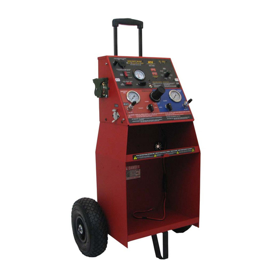
PART 2: WHAT’S INCLUDED PART 2: WHAT’S INCLUDED Handle Mute Switch Electrical Testing Main Power Panel Switch Trailer Type Switch 12 Pin NATO Out to Trailer Fuse Emergency Side Gauge 7 Round Pin Out to Shop Air Inlet Trailer 12 Pin NATO Output Service Side Gauge Emergency Side Air Chassis Ground Outlet... -
Page 8: Part 3: Controls And Panels
PART 3: CONTROLS AND PANELS An overview of the MUTT ’s controls, inputs, outputs and their functions. ® 3.1 LEFT AND RIGHT SIDE PANELS Left Side Right Side A. 12-PIN NATO CABLE OUT TO TRAILER For testing the integrity of a NATO pin trailer cable. Can also be used to verify that the MUTT is operating correctly. -
Page 9: Electrical Control Panel
3.2 ELECTRICAL CONTROL PANEL OBILE NIVERSAL RAILER ESTER NATO/7 SPADE/6/5/4 PIN MODE 7-WAY ROUND PIN MODE GROUND INTEGRITY CLEARANCE REVERSE TAIL LIGHTS LEFT TURN LEFT TURN VISIBLE ALERTS PROGRAM REMOTE: BRAKE Ground Integrity: During startup, all B/O STOP Hold down large button on remote while circuits blinking indicate poor ground ELEC. -
Page 10: Air Brake Control Panel
3.3 AIR BRAKE CONTROL PANEL Air Brake Control Panel A. Air Pressure Gauge - Emergency Side B. Air Out to Red Hose - Emergency Side C. Emergency Side Air Ball Valve D. Air Regulator Knob E. Air Pressure Gauge - Service Side F. -
Page 11: Part 4: Set-Up
PART 4: SET-UP 4.1 CHOOSING A BATTERY DC POWER The MUTT is a 12/24V DC device. Attempting to power ® Do not plug directly into your MUTT with anything other than a 12 or 24 volt DC ® AC wall outlet power source will destroy the internal circuitry and void your warranty. -
Page 12: Part 5: Pretesting Checklist
PART 5: PRETESTING CHECKLIST The pretesting checklist should always be completed prior to using the MUTT ® UNIT PLACEMENT • Place the tester on a flat, level surface. • Chock trailer wheels to avoid rolling before testing brakes. MAINTAIN CONNECTORS Dielectric grease should be used on all connections to avoid corrosion. -
Page 13: Part 6: General Controls And Operations
PART 6: GENERAL CONTROLS AND OPERATIONS 6.1 INITIAL STARTUP AND SHUTDOWN All functions of the MUTT , including air brake controls, require the Power Source ® Switch to be in BATTERY or EXTERNAL position. POWERING UP 1. Push the Power Source Switch to BATTERY or EXTERNAL. AMPERES Set Power Source to BATTERY or EXTERNAL POWERING DOWN... -
Page 14: Using The 3-Button Remote Control
6.3 USING THE 3-BUTTON REMOTE CONTROL The included remote control(s) is preprogrammed to your MUTT and should never ® lose its programming. In the event that you suspect your remote has lost its program- ming, contact technical support at 888-786-7899 or email tech247@ipatools.com. HOW TO PROGRAM THE 3-BUTTON REMOTE 1. -
Page 15: Using The 12-Button Remote Control
6.4 USING THE 12-BUTTON REMOTE CONTROL The included remote control(s) is preprogrammed to your MUTT and should never ® lose its programming. In the event that you suspect your remote has lost its program- ming, contact technical support at 888-786-7899 or email tech247@ipatools.com. HOW TO PROGRAM THE 12-BUTTON REMOTE 1. -
Page 16: Part 7: Electrical/Lighting Testing
PART 7: ELECTRICAL/LIGHTING TESTING Complete the pretesting checklist prior to all testing procedures. The MUTT is microprocessor controlled and features a special diagnostic firmware, ® designed to seamlessly integrate with your preferred methods of testing. The MUTT ® will power the selected electrical circuits and instantly alert you to any signs of a faulty condition. -
Page 17: Ground Integrity Test
7.2 GROUND INTEGRITY TEST Each time the MUTT is powered on, it automatically runs a Ground Integrity Test. A good ® ground connection must be established for the MUTT to operate a trailer’s electrical system. ® 1. Immediately after power up, the green lights around the control knob will illuminate. 2. -
Page 18: Fault Indication
7.3 FAULT INDICATION OPEN CIRCUIT The MUTT senses no load which is often the symptom of a disconnected wire, cut ® wire, poor pin connection or bad return ground. The MUTT can detect open circuits in ® two ways. 1. During Ground Integrity Test: An individual circuit will blink and no audible alerts will be present. -
Page 19: Short/Overloaded Circuit
NOTE: In some cases, a crossed circuit may be a normal function of advanced diagnostic testing, such as with certain ABS systems. SHORT/OVERLOADED CIRCUIT Short circuits or overloads can occur when a positive, hot wire touches ground. They can also occur due to faulty lights or connectors. 1. -
Page 20: Activating Hazard Lights
7.4 ACTIVATING HAZARD LIGHTS: The four-way flashers on the vehicle can be activated with the remote control. 3-Button Remote Control 1. To activate, press and hold the DOWN ARROW for five seconds. Press and Hold DOWN ARROW to Activate 12-Button Remote Control 1. -
Page 21: All Circuits On (Override) Mode
7.5 ALL CIRCUITS ON (OVERRIDE) MODE: All Circuits On Mode will engage all electrical circuits at the same time. While short circuit sensing is operational in this mode, if a short circuit is found, the MUTT will ® not be able to identify which circuit is the cause of the short. Open and crossed circuits sensing is not operational in this mode. -
Page 22: Part 8: Air Brake Testing
PART 8: AIR BRAKE TESTING Complete the pretesting checklist prior to all testing procedures. DANGER CHOCK TRAILER WHEELS WARNING!!! DO NOT CONNECT SHOP AIR UNTIL COMPLETING THE TESTING SETUP PROCEDURE STEPS 1-5. FAILURE TO FULLY UNDERSTAND THESE WARNINGS CAN RESULT IN MINOR TO SERIOUS INJURY AND POSSIBLY DEATH. -
Page 23: Setting Desired Working Pressure
8.2 SETTING DESIRED WORKING PRESSURE Set Emergency Side Air Ball Valve to OPEN, Turn Regulator to Desired PSI 1. Turn the MUTT on, by selecting Battery or External power with the Power Source ® Switch. 2. Set Emergency Side Air Ball Valve to the OPEN position. 3. -
Page 24: Leak Down Testing
8.3 LEAK DOWN TESTING You must always test the Emergency Side before testing the Service Side. Trying to test the Service Side first will result in erroneous readings. EMERGENCY SIDE LEAK DOWN TESTING Set Emergency Side Air Ball Valve to CLOSED 1. -
Page 25: Actuating Air Brakes
8.4 ACTUATING BRAKES This feature allows you to see the slacker adjustments and the pushrod travel in real time. Brakes can be activated manually or with the remote control. ACTUATE BRAKES MANUALLY Engage Brakes Disengage Brakes 1. Charge the Emergency Side to the desired working pressure and leave both the Emergency and Service Side Air Ball Valves in the OPEN position. -
Page 26: Emergency Air Exhaust
8.5 EMERGENCY AIR EXHAUST To apply the parking brake at any time during testing, simply turn the Emergency Side Air Ball Valve to the EXHAUST position. 1. Make sure the Power Source Switch on the Control Panel is on. 2. Set the Emergency Side Air Ball Valve to the EXHAUST position to exhaust air. Set Emergency Side Air Ball Valve to EXHAUST... -
Page 27: Part 9: Abs Blink Code Diagnostics
PART 9: ABS BLINK CODE DIAGNOSTICS The MUTT can be used to access ABS Blink Codes on trailers equipped with ® ABS systems. Trailers equipped with ABS feature an ABS Control Unit (ECU) which detects any electrical fault in the trailer ABS. Most trailers with ABS will also have a dedicated ABS lamp on the driver side. -
Page 28: Meritor/Wabco Blink Codes
9.1 MERITOR/WABCO BLINK CODES To access Meritor/WABCO blink codes, you must select the Auxiliary Circuit to power ON/OFF/ON in one second intervals using the following directions: 1. Make sure trailer is stationary and wheels are properly chocked. 2. On the MUTT , turn the control knob to the Auxiliary Circuit. -
Page 29: Haldex Blink Codes
9.2 HALDEX BLINK CODES To access Haldex Blink Codes, you must select the Brake Light Circuit and press the control knob to cycle the Auxiliary Circuit the appropriate number of times using the following directions: See table below for modes and sequences: Mode Description Ignition Cycles (Hold 1 Second ON/OFF) - Page 30 Fault Explanation Possible Causes Select Select Code System OK (with vehicle traveling ABS is operational displays “00” > 6 mph). when traveling > 6 MPH. Red channel wheel speed sensor Indicates a wheel speed sensor or wiring S1A has an open or short its wiring has short or open circuit.
- Page 31 Fault Explanation Possible Causes Select Select Code Loose sensor, connection, bracket Red channel wheel speed sensor or exciter, damaged exciter, sensor S1A has an erratic output voltage. is not properly adjusted or has worn cable insulation, or worn sensor block clip, wheel bearing Red channel wheel speed sensor failure, wheel bearing is not properly S1B has an erratic output voltage.
- Page 32 Fault Explanation Possible Causes Select Select Code For a 2M System, verify sensor and Slow wheel recovery on Red valve valve wiring/plumbing is correct. channel. (See Side-By-Side and Axle-By-Axle configurations). Slow brake release, Slow wheel recovery on Blue valve foundation brake mechanical faults, channel.
- Page 33 Fault Explanation Possible Causes Select Select Code Output leakage or poor insulation on any of the valve channels. Hold solenoid short circuit to perma- nent power on Red valve channel. Modulator valve solenoid failure or valve cable damage. Indicates that the Hold solenoid short circuit to perma- solenoid or its cable has a short circuit nent power on Blue valve channel.
-
Page 34: Bendix Blink Codes
9.3 BENDIX BLINK CODES To access Bendix Blink Codes you must select the Auxiliary Circuit and press the control knob to cycle the Brake Light Circuit the appropriate number of times using the following directions: See table below for modes and sequences: Mode Cycle Brake Light Power Display Active DTCs... - Page 35 SAL Sensor configuration error Verify correct ABS configuration using blink codes or other diagnostic tools. SAR Sensor configuration error If needed, reset to the default ABS configuration and power-up to initi- ate auto-configuration. POWER Over-voltage Power supply diagnostic trouble code. Low-voltage Power supply diagnostic trouble code.
- Page 36 ELECTRONIC CONTROL UNIT (ECU) ECU internal error Check for damaged or corroded connectors. Check for damaged wiring. After repairs or if no issues found, then clear faults. If faults return, replace the TABS-6 Module. ECU configuration error Verify correct ABS configuration using blink codes, PC-diagnostics or other off-board diagnostic tools.
-
Page 37: Part 10: Typical Trailer Wiring
PART 10: TYPICAL TRAILER WIRING Note: Not all trailers/vehicles are wired to this standard. The use of an electrical circuit tester is necessary to ensure proper match of vehicle’s wiring to trailer’s wiring. On some trailers with 6-way round plugs, the 12V wire and electric brake wire may be reversed (particularly horse trailers). -
Page 38: Part 11: Maintenance And Storage
PART 11: MAINTENANCE AND STORAGE • Switch power to OFF, remove all power cables, and disconnect battery before storing and cleaning. • Wipe surfaces down with a well-wrung, soft, damp cloth. • Diluted dishwashing liquid or similar substance can be used in the dampened cloth if necessary. -
Page 39: Part 13: Optional Accessories And Related Products
PART 13: OPTIONAL ACCESSORIES AND RELATED PRODUCTS #9008-SE SUPER MUTT BASE MODEL: 3-Button Remote Control, 5' 7-Way ® Cable, 8' Glad Hands. #9049M FLEET TANK SWEEPER : Extra 10 Micron Filter, Intake and ® Output Hoses, Output and Input Wands. #9060C MOBILE TIRE PRESSURE EQUALIZER: Five Color-Coded Air Hoses;... - Page 40 Innovative Products of America ® Incorporated will repair or replace the product within 24 working hours after it is received by the IPA Repair Service Center. In the event it is determined that the ®...
Need help?
Do you have a question about the NATO MUTT M2000 and is the answer not in the manual?
Questions and answers