Table of Contents
Advertisement
Quick Links
Advertisement
Table of Contents

Related Manuals for iPA SMART MUTT 9004A


Summary of Contents for iPA SMART MUTT 9004A
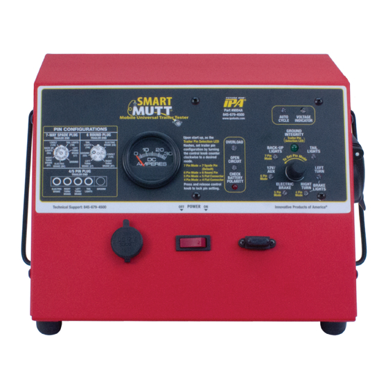
- Page 1 Mobile Universal Trailer Tester SMART MUTT (7 Spade Pin) ® #9004A OPERATOR’S MANUAL Portable Unit for Light-Duty Trailer Lights and Electric Brakes Innovative Products of America Incorporated ® 888-786-7899 • 234 Tinker Street, Woodstock, NY 12498 • www.ipatools.com...
- Page 2 LETTER FROM THE PRESIDENT OF IPA ® My name is Peter Vinci and I am the president of IPA . I would like to thank you for ® your interest in IPA ’s product line and share my commitment to you, our products ®...
-
Page 3: Table Of Contents
TABLE OF CONTENTS PART 1: IMPORTANT SAFETY INSTRUCTIONS PART 2: WHAT’S INCLUDED PART 3: CONTROLS AND PANELS PART 4: SET-UP 4.1 Choosing a Battery PART 5: PRETESTING CHECKLIST PART 6: GENERAL CONTROLS & OPERATIONS 6.1 Initial Startup and Shutdown 6.2 Auto Shutdown Feature 6.3 Using the 3-Button Remote Control PART 7: ELECTRICAL/LIGHTING TESTING 7.1 Selecting a Circuit... -
Page 4: Part 1: Important Safety Instructions
PART 1: IMPORTANT SAFETY INSTRUCTIONS IT IS IMPORTANT TO READ, UNDERSTAND AND FOLLOW ALL SAFETY MESSAGES AND INSTRUCTIONS PRINTED IN THIS MANUAL AND ON THE EQUIPMENT BEFORE OPERATING. IF SAFETY INFORMATION IS NOT HEEDED, SERIOUS INJURY OR DEATH TO THE OPERATOR OR BYSTANDERS MAY OCCUR. DANGER Indicates a hazardous situation, if not avoided, will result in death or serious injury. - Page 5 BATTERY GASES, TESTER PREPARATION AND TESTER/CHARGER LOCATION RISK OF EXPLOSION • Gases produced by a battery are highly explosive. • Wear safety goggles and protective clothing, both users and bystanders. • Use in an area having at least four air changes per hour. •...
- Page 6 GENERAL CHARGER USE RISK OF ELECTRIC SHOCK AND FIRE • Before connecting charger to unit, make sure controls are set to OFF. DO NOT • Do not remove or bypass the grounding pin. Plug Directly Into • Do not operate charger with damaged cord or plug. AC Wall Outlet Replace cord or plug immediately if damage occurs.
-
Page 7: Part 2: What's Included
PART 2: WHAT’S INCLUDED AUTO VOLTAGE CYCLE INDICATOR PIN CONFIGURATIONS GROUND INTEGRITY 7-WAY SPADE PLUG 6 ROUND PLUG Trailer Pin TRAILER END TRAILER END Selection LED 12VOLT TAIL LIGHTS TAIL ELECTRIC (12V) (TM) LIGHTS BRAKE (EB) BACK-UP TAIL (TM) BACK-UP LEFT LIGHTS LIGHTS... -
Page 8: Part 3: Controls And Panels
PART 3: CONTROLS AND PANELS An overview of the MUTT ’s controls, inputs, outputs and their functions. ® AUTO VOLTAGE CYCLE INDICATOR PIN CONFIGURATIONS 7-WAY SPADE PLUG 6 ROUND PLUG GROUND TRAILER END TRAILER END INTEGRITY 12VOLT TAIL LIGHTS TAIL Trailer Pin ELECTRIC Selection LED... -
Page 9: Part 4: Set-Up
PART 4: SET-UP 4.1 CHOOSING A BATTERY (Manufacturer’s Suggested Replacement: YUASA #YTX14 or Group 14 Equivalent) • Battery Voltage: 12/24V DC • Battery Type: Lead-Acid • Battery Compartment Dimensions: 5 7/8" L x 5 3/4" H x 3 3/8" W •... -
Page 10: Part 5: Pretesting Checklist
PART 5: PRETESTING CHECKLIST The pretesting checklist should always be completed prior to using the MUTT ® UNIT PLACEMENT • Place the tester on a flat, level surface. MAINTAIN CONNECTORS Dielectric grease should be used on all connections to avoid corrosion. If a bad connection exists at the terminal junction, you may get an erroneous reading and the MUTT will not work properly. -
Page 11: Part 6: General Controls & Operations
PART 6: GENERAL CONTROLS AND OPERATIONS 6.1 INITIAL STARTUP AND SHUTDOWN All functions of the MUTT require the Power Source Switch to be in the ON position. ® POWERING UP 1. Push the Power Source Switch to ON. Set Power Source to ON POWERING DOWN 1. -
Page 12: Using The 3-Button Remote Control
6.3 USING THE 3-BUTTON REMOTE CONTROL The included remote control(s) is preprogrammed to your MUTT and should never ® lose its programming. In the event that you suspect your remote has lost its program- ming, contact technical support at 888-786-7899 or email tech247@ipatools.com. HOW TO PROGRAM THE 3-BUTTON REMOTE 1. -
Page 13: Part 7: Electrical/Lighting Testing
PART 7: ELECTRICAL/LIGHTING TESTING Complete the pretesting checklist prior to all testing procedures. The MUTT is microprocessor controlled and features a special diagnostic firmware, ® designed to seamlessly integrate with your preferred methods of testing. The MUTT ® will power the selected electrical circuits and instantly alert you to any signs of a faulty condition. -
Page 14: Ground Integrity Test
7.2 GROUND INTEGRITY TEST Each time the MUTT is powered on, it automatically runs a Ground Integrity Test. ® A good ground connection must be established for the MUTT to operate a trailer’s ® electrical system. 1. Immediately after power up, the green lights around the control knob will illuminate. 2. -
Page 15: Crossed Circuits
CROSSED CIRCUITS The MUTT indicates that two or more circuits are back feeding or crossed. This ® can be a symptom of two wires in the same harness wearing through their insulated coating and connecting. 1. When a crossed circuit is identified, the selected circuit LED will illuminate steadily and the circuit it is crossed with will flash. -
Page 16: Activating Hazard Lights
7.4 ACTIVATING HAZARD LIGHTS The four-way flashers on the trailer can be activated with the 3-Button Remote Control. 3-Button Remote Control 1. To activate, press and hold the DOWN ARROW button for five seconds. Press and Hold DOWN ARROW to Activate 7.5 ALL CIRCUITS ON (OVERRIDE) MODE All Circuits On Mode will engage all electrical circuits at the same time. -
Page 17: Electric Brake Testing
REMOTE CONTROL 1. To activate All Circuits On Mode press and hold UP ARROW for five seconds and then release. 2. To cancel, press and release either arrow. Press and Hold UP ARROW to Activate 7.6 ELECTRIC BRAKE TESTING 1. To inspect electric brakes, first set the trailer on a flat, level surface. Place chocks in front and behind the wheels on one side of the trailer. -
Page 18: Part 8: Typical Trailer Wiring
PART 8: TYPICAL TRAILER WIRING NOTE: Not all trailers/vehicles are wired to this standard. The use of an electrical circuit tester is necessary to ensure proper match of vehicle’s wiring to trailer’s wiring. On some trailers with 6-way round plugs, the 12V wire and electric brake wire may be reversed (particularly horse trailers). -
Page 19: Part 10: Optional Accessories And Related Products
PART 10: OPTIONAL ACCESSORIES AND RELATED PRODUCTS #9008-DL SUPER MUTT PRO EDITION: (1) 12-Button Remote, ® (2) 3-Button Remotes, Face Shield, 10-ft. Chassis Ground Cable, 7-Way Cable, 8-ft. Glad Hands, Battery Charger, External Power Adapter, Rain Cover #9005A SUPER MUTT SERVICE TRUCK EDITION: (1) 12-Button Remote, ®... - Page 20 Innovative Products of America ® Incorporated will repair or replace the product within 24 working hours after it is received by the IPA Repair Service Center. In the event it is determined that the ®...
Need help?
Do you have a question about the SMART MUTT 9004A and is the answer not in the manual?
Questions and answers