Table of Contents
Advertisement
Quick Links
#5700
Alpha MUTT
®
M
U
T
T
obile
niversal
railer
ester
Operator's Manual
Tests Trailers With 7-Way Round Pin Type Connections
(Uses External 12/24 Volt Battery or Power Source)
Innovative Products of America
Incorporated
®
888-786-7899 • 234 Tinker Street, Woodstock, NY 12498 • www.ipatools.com
© 2018 Innovative Products of America
Incorporated. All rights reserved. This material may not be reproduced, displayed,
®
modified or distributed without the express prior written permission of the copyright holder. For permission, contact info@ipatools.com.
1
Advertisement
Table of Contents

Subscribe to Our Youtube Channel
Related Manuals for iPA Alpha MUTT 5700


Summary of Contents for iPA Alpha MUTT 5700
- Page 1 #5700 Alpha MUTT ® obile niversal railer ester Operator’s Manual Tests Trailers With 7-Way Round Pin Type Connections (Uses External 12/24 Volt Battery or Power Source) Innovative Products of America Incorporated ® 888-786-7899 • 234 Tinker Street, Woodstock, NY 12498 • www.ipatools.com ©...
- Page 2 888-786-7899. Your satisfaction is more important to me than the sale itself. We will not be in business for long if we don’t make you completely happy with our products and service. I want IPA to be different and be known ®...
-
Page 3: Table Of Contents
TABLE OF CONTENTS PART 1: IMPORTANT SAFETY INSTRUCTIONS PART 2: WHAT’S INCLUDED PART 3: CONTROLS AND PANELS 3.1 Left, Right and Back Panels 3.2 Electrical Control Panel 3.3 Air Brake Control Panel PART 4: SET-UP 4.1 Choosing a Battery 4.2 Lifting the Unit PART 5: PRETESTING CHECKL IST 5.1 Cable Testing Procedure PART 6: GENERAL CONTROLS AND OPERATIONS... -
Page 4: Part 1: Important Safety Instructions
PART 1: IMPORTANT SAFETY INSTRUCTIONS IT IS IMPORTANT TO READ, UNDERSTAND AND FOLLOW ALL SAFETY MESSAGES AND INSTRUCTIONS PRINTED IN THIS MANUAL AND ON THE EQUIPMENT BEFORE OPERATING. IF SAFETY INFORMATION IS NOT HEEDED, SERIOUS INJURY OR DEATH TO THE OPERATOR OR BYSTANDERS MAY OCCUR. DANGER Indicates a hazardous situation, if not avoided, will result in death or serious injury. - Page 5 BATTERY GASES, TESTER PREPARATION AND TESTER/CHARGER LOCATION RISK OF EXPLOSION • Gases produced by a battery are highly explosive. • Wear safety goggles and protective clothing, both users and bystanders. • Use in an area having at least four air changes per hour. •...
- Page 6 GENERAL CHARGER USE RISK OF ELECTRIC SHOCK AND FIRE • Before connecting charger cable to unit, make sure controls are set to OFF. DO NOT • Do not remove or bypass the grounding pin. Plug Directly Into • Do not operate charger with damaged cord or plug. AC Wall Outlet Replace cord or plug immediately if damage occurs.
-
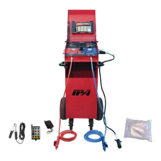
Page 7: Part 2: What's Included
PART 2: WHAT’S INCLUDED Face Shield Main Power Switch Mute 10" Tablet USB Tablet Charging Port 7-Way Round Pin LCD Menu Screen 7-Way Round Pin Tester Input Cable Out to Trailer Electrical Testing Panel Service-Side Air Out Shop Air (Blue Hose) Inlet Circuit Indicators Chassis... -
Page 8: Part 3: Controls And Panels
PART 3: CONTROLS AND PANELS An overview of the MUTT ’s controls, inputs, outputs and their functions. ® 3.1 LEFT, RIGHT AND BACK PANELS Left Side Right Side BACK A. 7-WAY ROUND PIN CABLE TEST INPUT For testing the integrity of a 7-way round pin trailer cable. Can also be used to verify that the MUTT is operating correctly. -
Page 9: Electrical Control Panel
3.2 ELECTRICAL CONTROL PANEL A. LCD MENU SCREEN B. LCD MENU CONTROL KNOB Knob activates all menu options and modes. C. BLUETOOTH PAIRED INDICATOR ® Steady blue light indicates paired device. D. CONTROL KNOB Knob activates all electrical test modes and circuits to be diagnosed. E. -
Page 10: Air Brake Control Panel
L. HAZARD BUTTON Activates the four-way flashers on trailer. M. 30 AMP FUSE SOCKET Overload protection. N. MUTE BUTTON Mute all alerts. 3.3 AIR BRAKE CONTROL PANEL AIR BRAKE CONTROLS EMERGENCY SERVICE SIDE SIDE WARNING: CHOCK ALL TRAILER WHEELS BEFORE APPLYING AIR PRESSURE 80 100 80 100 PULL KNOB TO ADJUST... -
Page 11: Part 4: Set-Up
PART 4: SET-UP 4.1 CHOOSING A BATTERY DC POWER The MUTT is a 12/24V DC device. Attempting to power ® Do not plug directly into your MUTT with anything other than a 12 or 24 volt DC ® AC wall outlet power source will destroy the internal circuitry and void your warranty. -
Page 12: Part 5: Pretesting Checklist
PART 5: PRETESTING CHECKLIST The pretesting checklist should always be completed prior to using the MUTT ® UNIT PLACEMENT • Place the tester on a flat, level surface. • Chock trailer wheels to avoid rolling before testing brakes. MAINTAIN CONNECTORS Dielectric grease should be used on all connections to avoid corrosion. -
Page 13: Part 6: General Controls And Operations
PART 6: GENERAL CONTROLS AND OPERATIONS 6.1 INITIAL START-UP AND SHUTDOWN All functions of the MUTT , including air brake controls, require the Power Source ® Switch to be in BATTERY or EXTERNAL position. POWERING UP 1. Push the Power Source Switch to BATTERY or EXTERNAL. BATTERY Set Power Source to BATTERY or EXTERNAL POWERING DOWN... -
Page 14: Using The 3-Button Remote Control
6.3 USING THE 3-BUTTON REMOTE CONTROL The included remote control(s) is preprogrammed to your MUTT and should never lose ® its programming. In the event that you suspect your remote has lost its programming, contact Technical Support at 888-786-7899 or email tech247@ipatools.com. HOW TO PROGRAM THE 3-BUTTON REMOTE 1. -
Page 15: Using The Tablet
6.5 Using the Tablet The Alpha MUTT comes equipped with a Samsung Galaxy Tablet, Model TAB A with ® 10.1" screen running on an Android Operating System. These tablets are industry leading for performance, battery life, screen resolution and security integration. Multi-view Charging Port Home... - Page 16 OPERATING THE APP Your Trailer Tester Application can be found on the Home Screen of the tablet. Press the icon to launch the application. The application is designed to be intuitive and easy to use. Review the Application Overview Guide for basic operation flow. For technical assistance, please call 888- 786-7899.
-
Page 17: Part 7: Electrical/Lighting Testing
PART 7: ELECTRICAL/LIGHTING TESTING Complete the pretesting checklist prior to all testing procedures. The MUTT is microprocessor controlled and features a special diagnostic firmware, ® designed to seamlessly integrate with your preferred methods of testing. The MUTT ® will power the selected electrical circuits and instantly alert you to any signs of a faulty condition. -
Page 18: Ground Integrity Test
7.2 GROUND INTEGRITY TEST Each time the MUTT is powered on, it automatically runs a Ground Integrity Test. A good ® ground connection must be established for the MUTT to operate a trailer’s electrical system. ® 1. Immediately after power up, the green lights around the Control Knob will illuminate. 2. -
Page 19: Fault Indication
7.3 FAULT INDICATION OPEN CIRCUIT When the MUTT senses no load, it is often a symptom of a disconnected wire, cut ® wire, poor pin connection or bad return ground. The MUTT can detect open circuits ® in two ways. 1. -
Page 20: Short/Overloaded Circuit
NOTE: In some cases, a crossed circuit may be a normal function of advanced diagnostic testing, such as with certain ABS systems. SHORT/OVERLOADED CIRCUIT Short circuits or overloads can occur when a positive/hot wire touches ground. They can also occur due to faulty lights or connectors. 1. -
Page 21: Activating Hazard Lights
7.4 ACTIVATING HAZARD LIGHTS: The four-way flashers on the vehicle can be activated manually or with the remote control. MANUALLY 1. To activate, press the Hazard Button. Press the Hazard Button Once 2. To deactivate, press the Hazard Button again. Press the Hazard Button Again REMOTE CONTROL 1. -
Page 22: All Circuits On (Override) Mode
7.5 ALL CIRCUITS ON (OVERRIDE) MODE: All Circuits On Mode will engage all electrical circuits at the same time. While short circuit sensing is operational in this mode, if a short circuit is found, the MUTT will ® not be able to identify which circuit is the cause of the short. Open and crossed circuit sensing is not operational in this mode. -
Page 23: Part 8: Air Brake Testing
PART 8: AIR BRAKE TESTING Complete the pretesting checklist prior to all testing procedures. DANGER CHOCK TRAILER WHEELS WARNING!!! DO NOT CONNECT SHOP AIR UNTIL COMPLETING THE TESTING SET-UP PROCEDURE. FAILURE TO FULLY UNDERSTAND THESE WARNINGS CAN RESULT IN MINOR TO SERIOUS INJURY AND POSSIBLY DEATH. -
Page 24: Setting Desired Working Pressure
8.2 SETTING DESIRED WORKING PRESSURE Set Emergency-Side Air Ball Valve to OPEN, Turn Regulator to Desired PSI 1. Turn the MUTT on by selecting BATTERY or EXTERNAL power with the Power ® Source Switch. 2. Set the Emergency-Side Air Ball Valve to the OPEN position. 3. -
Page 25: Actuating Air Brakes
SERVICE-SIDE LEAK DOWN TESTING Set Service-Side Air Ball Valve to CLOSED 1. Set the Emergency-Side and Service-Side Air Ball Valves to the OPEN position. Set the Service-Side Brake Control Switch to the PRESSURIZE position. (This fills the Service Side air lines.) 2. -
Page 26: Emergency Air Exhaust
ACTUATE BRAKES WITH REMOTE CONTROL Press ON/OFF Button Set Service and Emergency-Side Air Ball Valves to OPEN 1. Charge the Emergency Side to the desired working pressure. 2. With both Air Ball Valves in OPEN position, set the Service-Side Brake Control Switch to REMOTE. -
Page 27: Part 9: Abs Blink Code Diagnostics
PART 9: ABS BLINK CODE DIAGNOSTICS The MUTT can be used to access ABS Blink Codes on trailers equipped with ABS ® systems. Trailers that are equipped with ABS feature an ABS Control Unit (ECU) which detects any electrical fault in the trailer ABS. Most trailers with ABS will also have a dedicated ABS lamp on the driver side. -
Page 28: Meritor/Wabco Blink Codes
9.1 MERITOR/WABCO BLINK CODES To access Meritor/WABCO blink codes, you must select the Auxiliary Circuit to power ON/OFF/ON in one-second intervals using the following directions: 1. Make sure the trailer is stationary and wheels are properly chocked. 2. On the MUTT , turn the Control Knob to the Auxiliary Circuit. -
Page 29: Haldex Blink Codes
9.2 HALDEX BLINK CODES To access Haldex Blink Codes, you must select the Brake Light Circuit and press the Control Knob to cycle the Auxiliary Circuit the appropriate number of times using the following directions: See table below for modes and sequences: Mode Description Ignition Cycles (Hold One Second ON/OFF) - Page 30 System OK (with vehicle traveling ABS is operational. Displays “00” > 6 mph). when traveling > 6 mph. Red channel wheel speed sensor wiring S1A has an Open or Short circuit. Indicates a wheel speed sensor or its Red channel wheel speed sensor wiring has short or open circuit.
- Page 31 Fault Explanation Possible Causes Select Select Code Loose sensor, connection, bracket or Red channel wheel speed sensor exciter, damaged exciter, sensor is not S1A has an erratic output voltage. properly adjusted or has worn cable Red channel wheel speed sensor insulation or worn sensor block clip, S1B has an erratic output voltage.
- Page 32 Fault Explanation Possible Causes Select Select Code For a 2M System, verify sensor and valve Slow wheel recovery on Red valve wiring/plumbing is correct. (See Side-By- channel. Side and Axle-By-Axle configurations). Slow brake release, foundation brake Slow wheel recovery on Blue valve mechanical faults, dry bushings, broken channel.
- Page 33 Fault Explanation Possible Causes Select Select Code Output leakage or poor insulation on any of the valve channels. Hold solenoid short circuit to Permanent Power on Red valve channel. Modulator valve solenoid failure or valve cable damage. Indicates that Hold solenoid short circuit to Permanent the solenoid or its cable has a short Power on Blue valve channel.
-
Page 34: Bendix ® Blink Codes
9.3 BENDIX BLINK CODES ® To access Bendix Blink Codes you must select the Auxiliary Circuit and press the ® Control Knob to cycle the Brake Light Circuit the appropriate number of times using the following directions: See table below for modes and sequences: Mode Cycle Brake Light Power Display Active DTCs... - Page 35 SAL Sensor configuration error. Verify correct ABS configuration using blink codes or other diagnostic tools. SAR Sensor configuration error. If needed, reset to the default ABS configuration and power-up to initiate auto-configuration. POWER Power supply diagnostic trouble Over-voltage. code. Power supply diagnostic trouble Low-voltage.
- Page 36 ELECTRONIC CONTROL UNIT (ECU) Check for damaged or corroded connectors. Check for damaged wiring. ECU internal error. After repairs or if no issues found, then clear faults. If faults return, replace the TABS-6 Module. Verify correct ABS configuration using blink codes, PC-diagnostics or other off-board diagnostic tools.
-
Page 37: Part 10: Typical Trailer Wiring
PART 10: TYPICAL TRAILER WIRING Note: The standard wiring pictured below is viewed from the front of the connector. Not all trailers/vehicles are wired to this standard. The use of an electrical circuit tester is necessary to ensure proper match of vehicle’s wiring to trailer’s wiring. -
Page 38: Part 11: Maintenance And Storage
PART 11: MAINTENANCE AND STORAGE • Switch power to OFF, remove all power cables and disconnect battery before storing and cleaning. • Wipe surfaces down with a well-wrung, soft, damp cloth. • Diluted dishwashing liquid or similar substance can be used in the dampened cloth if necessary. -
Page 39: Part 13: Optional Accessories And Related Products
PART 13: OPTIONAL ACCESSORIES AND RELATED PRODUCTS #9008-DL SUPER MUTT PRO EDITION: 12-Button Remote Control, (2) 3-Button ® Remote Controls, 5' 7-Way Cable, Chassis Ground Cable, External Battery Connector, 8' Gladhands, 10A Smart Battery Charger, Face/Battery Shield and Rain Cover. #9049M FLEET TANK SWEEPER (2) 17-Micron Filter, 6' Long 3/4"... - Page 40 Limited Three-Year Warranty #5700 ALPHA MUTT ® obile niversal railer ester Innovative Products of America has established a Limited Three-Year Warranty Policy ® for the #5700 Alpha MUTT (Mobile Universal Trailer Tester), not including any wearable ® parts, i.e. batteries (30-day warranty), battery clips, etc. Three-Year Limited Warranty/Return or Replace Policy: The product is covered for three years from the date of original user purchase under the stipulations of the Standard Warranty.
Need help?
Do you have a question about the Alpha MUTT 5700 and is the answer not in the manual?
Questions and answers