Table of Contents
Advertisement
Quick Links
Advertisement
Table of Contents

Related Manuals for Elcometer CG100ABDL


Summary of Contents for Elcometer CG100ABDL
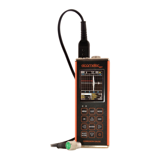
- Page 1 Model CG100ABDL, CG100BDL & CG100B Corrosion Gauge Operating Instructions...
- Page 2 Elcometer NDT Ultrasonic Couplant Material Safety Data Sheet : www.elcometerndt.com/images/MSDS/elcometer_ultrasonic_couplant_hi_temp.pdf All other trademarks acknowledged. © Elcometer Limited 2011/2012. All rights reserved. No part of this document may be reproduced, transmitted, transcribed, stored (in a retrieval system or otherwise) or translated into any language, in any form or by any means (electronic, mechanical, magnetic, optical, manual or otherwise) without the prior written permission of Elcometer Limited.
-
Page 3: Table Of Contents
12 Flaw Mode (CG100ABDL gauges only) ........ -
Page 4: About Your Gauge
Thank you for purchasing this Elcometer NDT product. Welcome to Elcometer NDT. The CG100 series of Corrosion Gauges are world beating products. With the purchase of these gauges you now have access to the worldwide service and support network of Elcometer. For more information visit our website at www.elcometer.com. -
Page 5: The Keypad
Data can be downloaded to a computer for analysis and storage. To maximise the benefits of your new Elcometer NDT gauge, please take some time to read these Operating Instructions. Do not hesitate to contact Elcometer NDT or your Elcometer NDT supplier if you have any questions. -
Page 6: Getting Started
Elcometer, the orientation of the dual coaxial connectors is not critical; either plug may be fitted to either socket. Further information on fitting the transducer can be found on the Elcometer NDT Knowledge Centre on www.elcometerndt.com. 3.3 SWITCHING ON/OFF To switch on or off, press the on/off key The gauge will switch off automatically after 5 minutes of inactivity. -
Page 7: The Measurement Screen
4.2 HOT KEY MENU (CG100ABDL gauges only) Press MEAS once to Press MEAS to scroll Use UP, DOWN, LEFT Alternatively, adjust access the right along the hot and RIGHT to adjust values by pressing measurement screen. menu functions and the value of the... - Page 8 • Gain Setting (VLOW, LOW, MED, HI, VHI) CG100B & CG100BDL • Gain Value - CG100ABDL only See “Measurement - Modes” on page 10 etc for further information Measurement View Area RF, RECT, B-SCAN or DIGITS view area. Measurement Labels...
- Page 9 5.2 RF A-SCAN MEASUREMENT SCREEN Hot Menu Disabled Hot Menu Enabled ((CG100ABDL gauges only) The RF view shows the full sound wave as received by the gauge. The vertical axis indicates the amplitude of the received wave and the horizontal position indicates the time it is received, which is converted into thickness units using the material velocity.
- Page 10 DELAY and RANGE - see instructions below. • Use the Auto Find function - see “Auto Find (CG100ABDL gauges only)” on page 18. Note: Even if the waveform is outside of the viewable range of the display, a measurement can be taken and viewed using the DIGITS view.
-
Page 11: Measurement - Modes
5.10 GATES (CG100ABDL gauges only) Your gauge is equipped with gates which control the time measurement process. For instructions on how to use gates, see “Gates (CG100ABDL gauges only)” on page 18. 6 MEASUREMENT - MODES Your gauge has two basic measurement modes, Pulse-Echo and Echo-Echo, plus a number of... - Page 12 6.6 COATING ONLY MODE (CT), COATING ONLY Note: Similar to the PECT mode but reports the coating thickness only. 6.7 FLAW MODE Your gauge includes a Flaw Mode. For instructions see “Flaw Mode (CG100ABDL gauges only)” on page 21. PECT PECT...
-
Page 13: Setting Up The Gauge
7 SETTING UP THE GAUGE 7.1 AUTOMATIC TRANSDUCER IDENTIFICATION If using a coating thickness transducer, the gauge will ask you to confirm the transducer type. 1. Press OK to use the identified transducer. Note: Always select OK to use the identified transducer type. 2. - Page 14 7.4 OFF BLOCK ZERO (AUTOMATIC PROBE ZERO) 1. When the ZERO PROBE screen is displayed, remove all couplant from the face of the transducer and check that the wearface of the transducer is clean and free of any debris. 2. Press OK (or ESC to cancel). When the automatic probe zero is completed the measurement screen is displayed.
- Page 15 1. Press MULTI, scroll to COATING ONLY (CT) and press ENTER.. The measurement screen is displayed. 2. Apply a drop of couplant on the transducer and place the transducer in steady contact with the probe zero disk (battery cover) and obtain a steady reading - see illustration. Note: Disregard the value displayed;...
- Page 16 7.7.2 Known Velocity Calibration If the material velocity is known, you can enter the velocity value directly into the gauge. A list of the sound velocities of common materials is given at the end of this instruction manual. 1. Select MENU CAL/VELOCITY . 2.
- Page 17 • In PECT mode a one point calibration is required • In CT mode a 2 - point calibration is required. 7.8.1 Known Coating Velocity If the coating velocity is known, you can enter the velocity value into your gauge. 1.
-
Page 18: Measurement - Taking Readings
5. Press ENTER to display the Digits Edit Box. 6. Press OK to set the coating velocity and return to the measurement screen, or ESC to cancel. Note: CHECK YOUR CALIBRATION. Place the transducer back on both calibration points. If the coating thickness readings match the known thickness values of each sample calibration has been successful and you are now ready to take measurements. -
Page 19: Gates (Cg100Abdl Gauges Only)
9 GATES (CG100ABDL gauges only) 9.1 INTRODUCTION Further information on gates may be found on the Elcometer NDT Knowledge Centre on www.elcometerndt.com 9.2 ADJUSTING THE GATES The quickest way to adjust the settings of the three gates is directly from the hot menu. Alternatively, adjust the values using the menus: 1. - Page 20 11.2 HIGH SPEED SCAN Although your gauge excels at making single point measurements, it is sometimes desirable to examine a larger region, searching for the thinnest point. The gauge includes a feature, called SCAN MODE, which allows it to do just that. This mode increases the overall repetition rate to a maximum of 50Hz with a high speed screen refresh rate of 25 times a second.
- Page 21 (above or below the x axis in the RF A-Scan) and the Rectified A-Scan display (whether the top or bottom half of the RF display is shown. For further information refer to the Elcometer NDT Knowledge Centre on www.elcometerndt.com. To adjust POLARITY: Set the measurement screen view to RF.
-
Page 22: Flaw Mode (Cg100Abdl Gauges Only)
12 FLAW MODE (CG100ABDL gauges only) 12.1 INTRODUCTION Your gauge includes a basic flaw prove up mode. Further information on flaw detection can be found on the Elcometer NDT Knowledge Centre on www.elcometerndt.com 12.2 FLAW MODE VIEW Feature Description Horizontal gridlines on the display represent... -
Page 23: Measurement - Recording Your Readings (Cg100Dl Gauges Only)
13 MEASUREMENT - RECORDING YOUR READINGS (CG100DL gauges only) Your gauge is equipped with a data logger -. With a data file open, all your measurements are saved into the file for later review and download to PC. 13.1 ABOUT THE DATA LOGGER With a data file open, as you take measurements, the measurement data is stored in files in the gauge memory. - Page 24 13.2 CREATING A NEW DATA LOGGER FILE - GRID FORMAT To create a GRID log data file: 1. Select MENU/DATA/NEW 2. Use (LEFT) or (RIGHT) to choose between grid and sequential log types 3. Press ENTER to continue 4. Fill in a name and a note (if desired) for your data logger file 5.
- Page 25 Note: Once the file is open, it will remain open until it is closed or another file is opened. If the gauge is switched off, the file will be opened automatically when the gauge is switched on again. Press the ENTER key to display the file from the measurement screen. 2.
-
Page 26: Gauge Setups
13.8 DELETING A DATA LOGGER FILE 1. Select MENU/DATA/DELETE ONE FILE. 2. Press ENTER. The OPEN LOG screen is displayed and lists all the data files stored in your gauge memory. 3. Scroll through the list until the data file you want to delete is highlighted. 4. -
Page 27: Data Transfer Software
15 DATA TRANSFER SOFTWARE Software is available which allows data to be transferred from your gauge to a PC. Presently Elcometer supplies NDT Link software for this purpose. To set-up other types of communications software: 1. Start the communications software. -
Page 28: Storage
The gauge does not contain any user-serviceable components. In the unlikely event of a fault, the gauge should be returned to your local Elcometer NDT supplier or directly to Elcometer NDT. The warranty will be invalidated if the instrument has been opened. -
Page 29: Technical Specification
18 TECHNICAL SPECIFICATION 18.1 PERFORMANCE Range Pulse-Echo P-E 0.63 mm to 500 mm (0.025” to 19.999”) Pulse-Echo Coating PECT Material: 0.63 mm to 500 mm (0.025” to 19.999”) Coating: 0.01 mm to 2.54 mm (0.001” to 0.100”) Pulse-Echo Temp Comp 0.63 mm to 500 mm (0.025”... -
Page 30: Warranty
Additionally, Elcometer NDT warrants transducers and accessories against such defects for a period of 90 days from receipt by the end user. If Elcometer NDT receives notice of such defects during the warranty period, Elcometer NDT will either, at its option, repair or replace products that prove to be defective. -
Page 31: Condition And Preparation Of Surfaces
10 MHz 3/16” Microdot Side Mini Angle Beam Transducer, 70 Degree TF10M0B70M-1 Calibration blocks Elcometer NDT offer a comprehensive range of calibration blocks to suit a wide range of applications and standards. Selecting the correct calibration block for the application is essential to ensure accurate evaluation. -
Page 32: Sound Velocities Of Common Materials
23 SOUND VELOCITIES OF COMMON MATERIALS Sound velocity Sound velocity Material Material (m/s) (in/µs) (m/s) (in/µs) Aluminium 6350 0.250 Paraffin 2210 0.087 Bismuth 2184 0.086 Platinum 3962 0.156 Brass 4394 0.173 Plexiglas 2692 0.106 Cadmium 2769 0.109 Polystyrene 2337 0.092 Cast Iron 4572 0.180... -
Page 33: The Menu Commands
24 THE MENU COMMANDS Menu Function Description ZERO PROBE Zeros your gauge in much the same way that a mechanical (PROBE) micrometer is zeroed. If your gauge is not zeroed correctly, all of the measurements made may be in error by some fixed value. - Page 34 Menu Function Description DISP VIEW Choose between RF wave, RECT (rectified) wave, BSCAN (DISPLAY) (cross section), and DIGITS (large digits) views. DELAY Adjust where the left side of the display window starts (B-START) according to thickness, in inches or millimetres. RANGE Set the overall depth of the viewable measurement area.
- Page 35 Menu Function Description GATE2 WIDTH Sets the overall width of the gate, in terms of distance, from (GATE 2) the starting value of HOLDOFF 2. (ABDL only) HOLDOFF 2 Delay the starting point of Gate2 a specific distance from the first detection point found inside of the boundaries of the Gate 1 settings.
- Page 36 DATA a computer to your gauge via the RS232 port. ABOUT Provides Elcometer NDT contact information and your gauge software version. Refer to the help section of your gauge NDT Link software for a complete electronic manual covering data transfer.
-
Page 37: Index
26 INDEX Adjusting the Gates Known Material Calibration Alarm Attenuation Attenuator Measurement Modes Auto Find Measurement Procedure Automatic Transducer Identification Measurement Screens Measuring Coatings Memory Batteries B-SCAN Measurement Screen B-Scan Scroll Speed Off Block Zero On Block Zero One Point calibration Calibration Calibration One Point 16, 17... - Page 38 Transducer delay line Tuning Two Point Calibration Viewable Range Viewing Readings Wide Pulse Zero Coating Zeroing...
Need help?
Do you have a question about the CG100ABDL and is the answer not in the manual?
Questions and answers