Table of Contents
Advertisement
Advertisement
Table of Contents

Subscribe to Our Youtube Channel
Related Manuals for Elcometer CG30


Summary of Contents for Elcometer CG30
- Page 1 Model CG30 Model CG50, CG50DL Corrosion Gauge Operating Instructions...
- Page 2 These operating instructions are available for download on our website www.elcometerndt.com. The following trademark is a registered trademark of Elcometer Limited, Edge Lane, Manchester, M43 6BU. United Kingdom: All other trademarks acknowledged.
-
Page 3: Table Of Contents
Contents About your gauge ............3 The keypad. -
Page 4: About Your Gauge
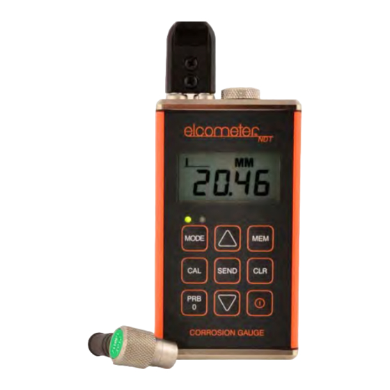
• The Model CG30 is the basic model. • The Model CG50 includes all features of the CG30 plus differential mode, an alarm and data output. • The Model CG50DL model includes all the features of the Model CG50 model plus a data-logging (memory) facility which allows readings to be stored in batches before being downloaded to a computer. - Page 5 Your gauge is packed inside its carrying case within a cardboard box. Please ensure that this packaging is disposed of in an environmentally sensitive manner. Please consult your Local Environmental Authority for further guidance. Model CG30 Model CG50 Model CG50DL MODE SCAN SEND CORROSION GAUGE Figure 1. Models CG30 - CG50 - CG50DL...
-
Page 6: The Keypad
2 THE KEYPAD MODEL CG30 (6 BUTTONS) AND CG50 (9 BUTTONS) Press to switch the gauge on or off. CG30 When switching off, the gauge retains all of its settings. CG50 If the gauge is idle for 5 minutes, it will switch itself off. -
Page 7: Getting Started
To fit or replace batteries: 1. Locate battery compartment cover (Figure 2) at top of gauge. Elcometer 206 Elcometer 208 2. Unscrew battery compartment cover. 3. Referring to battery polarity instructions on rear of gauge, insert batteries into gauge ensuring correct polarity. - Page 8 Alternatively contact Elcometer NDT, your local Elcometer NDT supplier or visit www.elcometerndt.com. 3.3 FITTING THE TRANSDUCER The transducer transmits (see Figure 3) and receives ultrasonic sound waves that the gauge uses to calculate the thickness of the material being measured.
-
Page 9: The Display
4 THE DISPLAY Stability Units indicator (IN, MM (see IN/µs, below) MM/s) INMM/ s µ Thickness value/ Menu items Stability indicator One bar - no readings are being taken Less than 5 bars - reading is unstable and may be inaccurate More than 5 bars - reading is stable Refer to “Read display”... - Page 10 4. Press the transducer against the probe-disc, making sure that the transducer is flat against the surface (Figure 5). The display should show some thickness value, and nearly all the bars of the stability indicator should be illuminated. Elcometer 206 Elcometer 208 Figure 5. Transducer pressed against probe-disc 5.
- Page 11 5.2.1 One-point calibration This procedure requires a sample piece of the material to be measured, the exact thickness of which is known, e.g. from having been measured by some other means. 1. Switch on the gauge. 2. Set the zero point of the gauge - see “Transducer - Zeroing” on page 8. 3.
-
Page 12: Taking A Reading
5.2.3 Known velocity calibration This procedure requires that the operator knows the sound-velocity of the material to be measured. A table of common materials and their sound-velocities can be found in “Sound velocities of common materials” on page 24. 1. Press ON/OFF key to switch on the gauge. 2. -
Page 13: Measurement Options
This feature can be used in conjuction with the alarm limit feature. To switch scan mode on/off: Model CG50DL Model CG30/CG50 Switch on the gauge. Switch on the gauge. Press UP/SCAN key to toggle the status of Press MODE key to activate features and the Scan mode. - Page 14 7.2 DIFFERENTIAL MODE - CG50 AND CG50DL ONLY Your gauge includes Differential Mode which allows it to display the positive or negative difference from an entered nominal value. To switch differential mode on/off and enter the value: Model CG50 Model CG50DL 1.
- Page 15 To switch beeper on/off Model CG50 Model CG50DL 1. While the gauge is off, press and hold 1. Switch on the gauge. down ALRM key. 2. Press MODE key to activate features and 2. Switch on the gauge. settings. 3. Release ALRM key. 3.
-
Page 16: Measurement - Recording Your Readings (Cg50Dl Only)
AUTO - backlight automatically illuminates while the gauge is making a measurement and switches off after several seconds (to conserve battery life). To set backlight mode Model CG30/CG50 Model CG50DL 1. Switch on the gauge. 1. Switch on the gauge 2. - Page 17 • a measurement that was previously stored • CLr in the display, indicating that the memory location is empty • ObSt (obstruct) in the display, indicating that a measurement could not be obtained 7. Press the UP / DOWN arrow keys to advance to the desired memory location. 8.2 STORING A MEASUREMENT 1.
-
Page 18: Transferring Readings To A Computer - Cg50/Cg50Dl Only
Model CG50DL and is available as an optional accessory for the Model CG50 (see “Spares” on page 19). Elcometer NDT recommends the use of NDT Link communications software to transfer the data - see “Data transfer software” on page 23. Other types of software may also be used. -
Page 19: Storage
9.2.4 Installing NDT Link NDT Link comes on a CD-ROM with an automatic installer program. Place the CD in your computer's CD tray and close the door. Open the CD-ROM by double clicking on the My Computer ICON, then double click on the CD. Finally, double click on the SETUP icon to begin the installation. Refer to the help section in NDT Link software for the complete operating manual, setup, and operation. -
Page 20: Maintenance
The gauge does not contain any user-serviceable components. In the unlikely event of a fault, the gauge should be returned to your local Elcometer NDT supplier or directly to Elcometer NDT. The warranty will be invalidated if the instrument has been opened. Contact details can be found at www.elcometerndt.com. -
Page 21: Warranty
Additionally, Elcometer NDT warrants transducers and accessories against such defects for a period of 90 days from receipt by the end user. If Elcometer NDT receives notice of such defects during the warranty period, Elcometer NDT will either, at its option, repair or replace products that prove to be defective. - Page 22 The measurement range • The type of material to be tested • The design of the transducer probe type For full details of the Elcometer NDT range of transducers contact your local Elcometer NDT supplier, or visit the Elcometer NDT website www.elcometerndt.com...
-
Page 23: Condition And Preparation Of Surfaces
16 CONDITION AND PREPARATION OF SURFACES The shape and roughness of the test surface are of paramount importance when carrying out ultrasonic thickness testing. Rough, uneven surfaces may limit the penetration of ultrasound through the material, and result in unstable, and therefore unreliable, measurements. The surface being measured should be clean, and free of any small particles, rust, or scale. - Page 24 Presently Elcometer NDT supplies NDT Link. The Model CG50 gauge is supplied without any software but NDT Link is available as a free download from the Elcometer NDT website www.elcometerndt.com. The Model CG50DL gauge is supplied with a CD containing NDT Link.
-
Page 25: Sound Velocities Of Common Materials
18 SOUND VELOCITIES OF COMMON MATERIALS Sound-velocity Sound-velocity Sound-velocity Sound-velocity Material Material (m/s) (in/µs) (m/s) (in/µs) Aluminium 6350 0.CG30 Paraffin 2210 0.087 Bismuth 2184 0.086 Platinum 3962 0.156 Brass 4394 0.173 Plexiglas 2692 0.106 Cadmium 2769 0.109 Polystyrene 2337 0.092...
Need help?
Do you have a question about the CG30 and is the answer not in the manual?
Questions and answers