Table of Contents
Advertisement
Quick Links
Advertisement
Table of Contents

Subscribe to Our Youtube Channel
Related Manuals for Boser HS-7002


Summary of Contents for Boser HS-7002
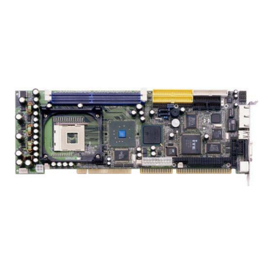
- Page 1 HS-7002 800MHz FSB Pentium® 4 Industrial Single Board Computer •Full-size•800MHz FSB•DDR•GPIO• •CRT/LVDS Panel•TV-Out•Dual Giga LAN• •Audio•Serial ATA•ATA/33/66/100• •RS-232/422/485•4 COM•PC/104•IrDA• •USB2.0•WDT•H/W Monitor• •PICMG Bus Industrial Single Board computer•...
- Page 2 Copyright Disclaimers The accuracy of contents in this manual has passed thorough checking and review before publishing. BOSER Technology Co., Ltd., the manufacturer and publisher, is not liable for any infringements of patents or other rights resulting from its use. The...
-
Page 3: Table Of Contents
Table of Contents Chapter 1 General Description……………………..1 Major Features ..............2 Specifications ...............3 Board Dimensions............4 Chapter 2 Unpacking………………………………..5 Opening the Delivery Package ........5 Inspection..............5 Chapter 3 Hardware Installation…………………...7 Before Installation ............7 Board Layout ..............8 Jumper List ..............9 Connector List ..............9 Configuring the CPU ..........10 System Memory ............10 VGA Controller............10 Serial ATA Function ............12... - Page 4 Chapter 4 Award BIOS Setup……………………..27 Starting Setup .............27 Using Setup..............28 Main Menu ..............29 Standard CMOS Features ..........30 Advanced BIOS Features ..........31 Advanced Chipset Features ........32 Integrated Peripherals..........33 Power Management Setup.........35 PnP/PCI Configurations ..........36 4.10 PC Health Status............36 4.11 Frequency/Voltage Control........37 4.12 Load Fail-Safe Defaults..........37 4.13...
- Page 5 Fasten the ALLIGATOR clip of the strap to the end of the shielded wire lead from a grounded object. Please wear and connect the strap before handling the HS-7002 to protect yourself from the discharge of any static electricity through the strap.
-
Page 7: General Description
TV-Out, dual Giga LAN, audio, serial ATA, 4 COM port interface, and more. Its onboard ATA/33/66/100 connected to IDE drive interface architecture allows the HS-7002 to support data transfers of 33, 66 or ® 100MB/sec. for each IDE drive connection. Designed with the Intel 82865GV/82801EB core logic chipset, the board supports all PGA 478 ®... -
Page 8: Major Features
RJ-45 connectors for use of one 100/1000 and one 10/100 OR two 10/100 Base-TX Ethernet interfaces. Major Features The HS-7002 comes with the following features: ® ® PGA 478 for Intel Pentium 4 CPU with Hyper-Threading Technology clocking up to 3.2GHz... -
Page 9: Specifications
Specifications ® ® CPU: PGA 478 for Intel Pentium 4 CPU with Hyper-Threading Technology clocking up to 3.2GHz Bus Interface: PICMG Bus Front Side Bus: Supports 400MHz/533MHz/800MHz FSB Memory: Two DDR sockets supporting DDR-266/333/400 up to 2GB ® Chipset: Intel 82865GV/82801EB I/O Chipset: Winbond W83627 x 2 ISA Bridge: ITE IT8888 (16-bit) -
Page 10: Board Dimensions
Board Dimensions... -
Page 11: Unpacking
Chapter 2 Unpacking Opening the Delivery Package The HS-7002 is packed in an anti-static bag. The board has components that are easily damaged by static electricity. Do not remove the anti-static wrapping until proper precautions have been taken. Safety Instructions in front of this manual describe anti-static precautions and procedures. - Page 12 It is recommended that you keep all the parts of the delivery package intact and store them in a safe/dry place for any unforeseen event requiring the returned shipment of the product. In case you discover any missing and/or damaged items from the list of items, please contact your dealer immediately.
-
Page 13: Hardware Installation
Chapter 3 Hardware Installation This chapter provides the information on how to install the hardware using the HS-7002. This chapter also contains information related to jumper settings of switch, watchdog timer selection, etc. Before Installation After confirming your package contents, you are now ready to install your hardware. -
Page 14: Board Layout
Board Layout... -
Page 15: Jumper List
Jumper List Jumper Default Setting Setting Page Use RS-232 or RS-422/485 Select: JP1 / JP2 / JP4 / JP5 2-3 Short RS-232 Clear CMOS: Normal Operation 1-2 Short Connector List Connector Definition Page CN1 / CN5 4-pin/20-pin ATX Power Connectors CN3 (1-3-5-7) Speaker Connector CN3 (9-11) -
Page 16: Configuring The Cpu
The onboard Intel 82865GV with 1MB/8MB/16MB (default) memory supports CRT displays up to 1600 x 1200 x 32-bit. The HS-7002 provides two methods of connecting VGA device. CN20 offers a single standard CRT connector (DB15). And J2, J3 offers LVDS Panel... - Page 17 CN20: 15-pin CRT Connector (DB15) Description Description Green Blue HSYNC VSYNC J1: Inverter Power Connector PIN Description VCC12 VCC12 VCC5 ENABKL ENAVDD J3: LVDS Panel Connector PIN Description PIN Description VCC3 VCC3 CLK1M CLK1P J2: LVDS Panel Connector PIN Description PIN Description VCC3 VCC3 CLK2M...
-
Page 18: Serial Ata Function
Serial ATA Function You can connect the Serial ATA device to this connector which provides you high speed transfer rates (150MB/sec.). If you wish to use RAID function, please note that these two Serial ATA connectors just support RAID0 and only compatible with WIN XP. J7: Serial ATA Connector Description SATA0TXP... -
Page 19: Pci E-Ide Drive Connector
PCI E-IDE Drive Connector CN7 and CN6 are standard 40-pin daisy-chain driver connectors that serve the PCI E-IDE drive provisions onboard the HS-7002. A maximum of four ATA/33/66/100 IDE drives can be connected to the HS-7002 via CN7 and CN6. - Page 20 CN6: Secondary IDE Connector Description Description RESET SDATA 7 SDATA 8 SDATA 6 SDATA 9 SDATA 5 SDATA 10 SDATA 4 SDATA 11 SDATA 3 SDATA 12 SDATA 2 SDATA 13 SDATA 1 SDATA 14 SDATA 0 SDATA 15 SDREQ SIOW# SIOR# SIORDY...
-
Page 21: Floppy Disk Drive Connector
3.10 Floppy Disk Drive Connector The HS-7002 uses a standard 34-pin header connector, CN10, for floppy disk drive connection. A total of two FDD drives may be connected to CN10 at any given time. CN10: FDD Connector Description Description DRVDEN0... -
Page 22: Serial Port Connectors
3.11 Serial Port Connectors The HS-7002's CN21, CN8, CN12 and CN14 provide four high speed NS16C550 compatible UART with Read/Receive 16 byte FIFO serial ports. CN21: COM1 Connector (5x2 Header) PIN Description PIN Description DCD0 DSR0 DCD0 DSR0 RXDD0 RTS0... -
Page 23: Irda Connector
CN14: COM4 Connector (5x2 Header) PIN Description PIN Description DCD3 DSR3 DCD3 DSR3 RXDD3 RTS3 RXDD3 RTS3 TXDD3 CTS3 TXDD3 CTS3 DTR3 DTR3 The onboard COM2 may be configured as RS-232, RS-422, or RS-485. CN11: RS-422/485 Connector (5x2 Header) PIN Description PIN Description RTS- RTS- RTS+... -
Page 24: Parallel Connector
3.13 Parallel Connector CN9 is a standard 26-pin flat cable connector designed to accommodate parallel port connection onboard the HS-7002. CN9: Parallel Connector Description PIN Description Strobe Auto Form Feed DATA 0 ERROR# DATA 1 Initialize DATA 2 Printer Select LN#... -
Page 25: Ethernet Connector
3.14 Ethernet Connector The HS-7002 provides one 10/100 and one 100/1000 OR two 10/100 Base-TX LAN interface connectors. Please refer to the following for its pin information. CN18: Dual RJ-45 Connector PIN Description PIN Description R/C GND R/C GND R/C GND... -
Page 26: Cmos Data Clear
The HS-7002 provides one 4-pin and one 20-pin ATX power connectors at CN1 and CN5. The HS-7002 must use P4 power supply. One of 4-pin connectors is for +12V lead which should be connected to CN1. A 20-pin ATX Power Connector can be connected to Backplane or to CN5. - Page 27 PWORK +5Vsb +12V CN23: 5-pin ATX Power Connector PIN Description PIN Description PS_ON +12V 5Vsb Connector FN1, FN2 and FN3 onboard HS-7002 are 3-pin fan power connectors. FN1~FAN3: Fan Power Connectors Description FAN In 1 +12V +12V Fan In 1...
-
Page 28: Keyboard/Mouse Connector
Mouse Clock 3.19 System Front Panel Connectors The HS-7002 has one system front panel connectors at location CN3 that indicates the power-on status. This visual feature of the IDE LED may also be connected to an external IDE LED via connector CN3(13-15). -
Page 29: Watchdog Timer
3.20 Watchdog Timer Once the Enable cycle is active, a Refresh cycle is requested before the time-out period. This restarts counting of the WDT period. When the time counting goes over the period preset of WDT, it will assume that the program operation is abnormal. A System Reset signal will re-start when such error happens. -
Page 30: Audio Connectors
AOUT_R MIC IN 3.22 TV-Out Function The HS-7002 can support TV-Out function whose input could be up to 800 x 600 graphics resolutions. World Wide Video standards are supported including NTSC-M (North America, Taiwan), NTSC-J (Japan), PAL-B, D, G, H, I (Europe, Asia), PAL-M (Brazil), PAL-N (Uruguay, Paraguay) and PAL-NC (Argentina). -
Page 31: Pc/104 Connectors
3.24 PC/104 Connectors The PC/104 expansion bus offers provisions to connect all types of PC/104 modules. With the PC/104 bus being known as the new generation of industrial embedded 16-bit PC standard bus, thousands of PC/104 modules from multiple vendors can be easily installed onboard. - Page 32 PC2: 64-pin PC/104 Expansion Slot Description PIN Description Connector diagram rotated 90 degrees IOCHECK* clockwise from RESETDRV original position IRQ9 DRQ2 -12V 0WS* +12V IOCHRDY SMEMW* SA19 SMEMR* SA18 IOW* SA17 IOR* SA16 DACK3* SA15 DRQ3 SA14 DACK1* SA13 DRQ1 SA12 REFRESH* SA11...
-
Page 33: Award Bios Setup
Chapter 4 Award BIOS Setup The HS-7002 uses Award BIOS for the system configuration. The Award BIOS setup program is designed to provide the maximum flexibility in configuring the system by offering various options that could be selected for end-user requirements. This chapter is written to assist you in the proper usage of these features. -
Page 34: Using Setup
Using Setup In general, you use the arrow keys to highlight items, press <Enter> to select, use the <PageUp> and <PageDown> keys to change entries, press <F1> for help and press <Esc> to quit. The following table provides more details about how to navigate in the Setup program using the keyboard. -
Page 35: Main Menu
Main Menu Once you enter the Award BIOS CMOS Setup Utility, the Main Menu will appear on the screen. The Main Menu allows you to select from several setup functions and two exit choices. Use the arrow keys to select among the items and press <Enter> to enter the sub-menu. Phoenix –... -
Page 36: Standard Cmos Features
Standard CMOS Features The Standard Setup is used for the basic hardware system configuration. The main function is for Data/Time and Floppy/Hard Disk Drive settings. Please refer to the following screen for the setup. When the IDE hard disk drive you are using is larger than 528MB, you must set the HDD mode to LBA mode. -
Page 37: Advanced Bios Features
Advanced BIOS Features This section allows you to configure your system for the basic operation. You have the opportunity to select the system’s default speed, boot-up sequence, keyboard operation, shadowing and security. Phoenix – AwardBIOS CMOS Setup Utility Advanced BIOS Features Virus Warning Disabled Item Help... -
Page 38: Advanced Chipset Features
Advanced Chipset Features This section allows you to configure the system based on the specific features of the installed chipset. This chipset manages bus speeds and the access to the system memory resources, such as DRAM and the external cache. It also coordinates the communications between the conventional ISA and PCI buses. -
Page 39: Integrated Peripherals
Integrated Peripherals The IDE hard drive controllers can support up to two separate hard drives. These drives have a master/slave relationship that is determined by the cabling configuration used to attach them to the controller. Your system supports two IDE controllers--a primary and a secondary--so you can install up to four separate hard disks. - Page 40 Phoenix – AwardBIOS CMOS Setup Utility Onboard Device USB Controller [Enabled] Item Help USB 2.0 Controller [Enabled] Menu Level USB Keyboard Support [Enabled] USB Mouse Support [Disabled] AC97 Audio [Auto] : Select Item + / - /PU/PD: Value F10: Save ESC: Quit F1: General Help F5: Previous Values...
-
Page 41: Power Management Setup
Power Management Setup The Power Management Setup allows user to configure the system for saving energy in a most effective way while operating in a manner consistent with his own style of computer use. Phoenix – AwardBIOS CMOS Setup Utility Power Management Setup ACPI function [Enabled]... -
Page 42: Pnp/Pci Configurations
PnP/PCI Configurations This section describes configuring the PCI bus system. PCI, or Peripheral Components Interconnect, is a system that allows I/O devices to operate at speeds nearing the speed the CPU itself uses when communicating with its own special components. This section covers some very technical items and it is strongly recommended that only experienced users should make any changes to the default settings. -
Page 43: Frequency/Voltage Control
4.11 Frequency/Voltage Control Phoenix – AwardBIOS CMOS Setup Utility Frequency/Voltage Control CPU Clock Ratio [8X] Item Help Auto Detect DIMM/PCI Clk [Enabled] Menu Level Spread Spectrum [Disabled] Change the day, month, year and century : Select Item + / - /PU/PD: Value F10: Save ESC: Quit F1: General Help... -
Page 44: Load Optimized Defaults
4.13 Load Optimized Defaults When you press <Enter> on this item you get a confirmation dialog box with a message similar to the figure below. This option allows you to load/restore the default values to your system configuration, optimizing and enabling all high performance features. Pressing ‘Y’ loads the default values that are factory settings for optimal performance system operations. -
Page 45: Set Supervisor/User Password
4.14 Set Supervisor/User Password Phoenix – AwardBIOS CMOS Setup Utility Standard CMOS Features Frequency/Voltage Control Advanced BIOS Features Load Fail-Safe Defaults Advanced Chipset Features Load Optimized Defaults Integrated Peripherals Set Supervisor Password Power Management Setup Set User Password PnP/PCI Configurati t Setup Enter Password : PC Health Status... -
Page 46: Save & Exit Setup
When a password has been enabled, you will be prompted to enter it every time you try to enter Setup. This prevents an unauthorized person from changing any part of your system configuration. Additionally, when a password is enabled, you can also require the BIOS to request a password every time your system is rebooted. -
Page 47: Exit Without Saving
4.16 Exit Without Saving Pressing <Enter> on this item asks for confirmation: Quit without saving (Y/N)? Y This allows you to exit Setup without storing in CMOS any change. The previous selections remain in effect. This exits the Setup utility and restarts your computer. - Page 48 This Page is intentionally left blank.
-
Page 49: Software Utilities
IDE Driver Installation 5.1.1 Installing Intel Chipset Software Utility Insert Utility CD Disk into your CD ROM drive. The main menu will pop up as shown below. Select on the HS-7002 button to launch the installation program. - Page 50 Click on the ICH5 Driver button to continue. Click on the Windows 9X button to continue.
- Page 51 Immediately after clicking the IDE button in Step 1, the program launches the InstallShield Wizard that will assist you in the installation process. Click on the Next > button to proceed. The Intel OEM Software License Agreement dialog box then appears on the screen.
- Page 52 When the Readme Information dialog box pops up, just click on the Next button to proceed. Once the Install Shield Wizard finishes updating your system, it will prompt you to restart the computer. Tick on the “Yes, I want to restart my computer now” followed by a click on the Finish button to reboot.
-
Page 53: Vga Driver Installation
VGA Driver Installation Insert Utility CD Disk into your CD ROM drive. The main menu will pop up as shown below. Select on the HS-7002 button to launch the installation program. Click on the VGA Driver button to continue. - Page 54 Click on the OS button to continue. When the dialog box below appears, make sure you close all other Windows applications and then click on the Next > button to proceed.
- Page 55 Immediately after clicking the IDE button in Step 1, the program launches the InstallShield Wizard that will assist you in the installation process. Click on the Next > button to proceed. The Intel OEM Software License Agreement dialog box then appears on the screen.
-
Page 56: Lan Driver Installation
Finish button to reboot. Only after your computer boots will the new settings take effect. LAN Driver Installation 5.3.1 Win 95/98/2K/XP Insert Utility CD Disk into your CD ROM drive. The main menu will pop up as shown below. Select on the HS-7002 button to launch the installation program. - Page 57 Click on the LAN Driver button to continue. Click on the WIN9X/WIN2K/WINXP button to continue.
- Page 58 The Intel OEM Software License Agreement dialog box then appears on the screen. Choose Accept to proceed. When the dialog box below appears, make sure the folder you’ll save file in, then Click on the Next >...
- Page 59 When the dialog box below appears, make sure you close all other Windows applications and then click on the Install Base Driver button to proceed. Once the setup program finishes copying files into your system, it will prompt you to restart the computer. Tick on the Restart now to reboot.
- Page 60 Tick on the Wired to Network once the following screen appears. Click on Next > to proceed. Click on the Start Search button for the program to locate the Network Adapter.
- Page 61 Once setup finishes the search, it will list a number of adapters for you to choose from. Press on the Have Disk button to assign the driver path location. Setup now asks you for the location of the driver. When you have entered the new driver path, press on the OK button to continue.
- Page 62 When Setup finds the information it needs about the new driver, it will display the device it found on the following screen. If using 82562EZ, please choose “Intel(R) PRO/100 Family Adapter”. If using 82540EM or 82547EI, please choose “Intel(R) PRO/1000 Family Adapter”. Press on the OK button to accept and proceed.
- Page 63 The Network Setup Wizard then allows you to set the Network Protocols on your network. Select the appropriate protocol and then click on Next to continue. Before Setup starts installing the components found and the settings you made, it will give you the option to proceed or go back for changes from the following screen.
- Page 64 10. Windows NT Setup will then need to copy files necessary to update the system information. Specify the path and then press Continue. 11. When Setup asks if you wish to change the TCP/IP settings of your system, select them appropriately. The default choice is No. 12.
- Page 65 14. Setup then prompts you that it is ready to start the network. You may complete the installation thereafter. Click on Next to continue. 15. Assign the workgroup or domain setting of your computer. Click on Next to continue.
- Page 66 16. Click on the Yes button to restart your computer. The LAN1 driver installation for WIN NT4.0 is now complete. 17. With the Utility CD Disk still in your CD ROM drive, we can install LAN2. Right click on “Network Neighborhood” icon from the desktop.
-
Page 67: Audio Driver Installation
19. Click on the Close button. The LAN2 driver installation for WIN NT4.0 is now complete. Audio Driver Installation Insert Utility CD Disk into your CD ROM drive. The main menu will pop up as shown below. Select on the HS-7002 button to launch the installation program. - Page 68 Click on the AUDIO Driver button to continue. Click on the OS button which you use.
- Page 69 When the dialog box below appears, make sure you close all other Windows applications and then click on the Next > button to proceed. Once the InstallShield Wizard completes the operation and update of your AC’97 driver, it will ask you to remove disks from their drives, and prompt you to restart your system.
-
Page 70: Usb2.0 Driver Installation
USB2.0 Driver Installation 5.5.1 Win 95/98 Insert Utility CD Disk into your CD ROM drive. The main menu will pop up as shown below. Select on the HS-7002 button to launch the installation program. Click on the USB2.0 Driver button to continue. - Page 71 Click on the WIN9x button to continue. The Intel OEM Software License Agreement dialog box then appears on the screen. Choose Yes to proceed.
- Page 72 Once the setup program finishes copying files into your system, it will prompt you to restart the computer. Tick on the “Yes, I want to restart my computer now” followed by a click on the Close button to reboot. Only after your computer boots will the new settings take effect.
- Page 73 The Universal Serial Bus (USB) Controller Properties screen then appears, allowing you to re-install the driver. Select Update Driver from the main menu to proceed. When the dialog box below appears, make sure you close all other Windows applications and then click on the Next > button to proceed.
- Page 74 Tick on the “Search for a suitable driver for my device (recommended)” once the following screen appears. Click on the Next to proceed. Once the program returns to the Add New Hardware Wizard screen, your specified location will appear. Press on the Next button to continue...
- Page 75 Choose sisusb2.inf and press on the Open button to accept and proceed. Once the InstallShield Wizard completes the operation and update of your USB2.0 driver, click on the Finish button to complete the installation process.
- Page 76 5.5.3 Win XP Please make sure you have already installed Service NOTE: Pack1. With the Utility CD Disk still in your CD ROM drive, right click on “My Computer” icon from the Windows menu. Select on System Properties and then proceed to the Device Manager from the main menu.
- Page 77 Once the InstallShield Wizard completes the operation and update of your USB2.0 driver, click on the Finish button to complete the installation process.
- Page 78 This page is intentionally left blank.
Need help?
Do you have a question about the HS-7002 and is the answer not in the manual?
Questions and answers