
Related Manuals for Response CWK5


Summary of Contents for Response CWK5
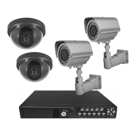
- Page 1 Camera Wired Coloured CCTV Kit CWK5 Installation and Operating Instructions These instructions should be retained in a safe place for future reference.
-
Page 2: Table Of Contents
CONTENTS INTRODUCTION System 6.5.1 Hard Disk Setup 2 KIT CONTENTS 6.5.2 Account Setup 6.5.3 Password Setup 3 DVR FEATURES 6.5.4 Clear Account Info 6.5.5 Keypad Tone 4 PHYSICAL UNIT 6.5.6 Time Set Front Panel 6.5.7 Event List 4.1.1 DVR Button Functions (Playback Feature) Rear Panel Language... -
Page 3: Introduction
The Response 4 Channel DVR provides a total video security solution for 4 channel digital surveillance supporting duplex (simultaneous playback and record) functionality. -
Page 4: Kit Contents
CONTENTS Section 2 x 4 Channel DVR unit (with a 160GB hard drive unit fitted in the drawer) x Wired Heavy Duty Colour Cameras 2 x Wired Internal Dome Colour Cameras 2 x 10m camera extension cable 2 x 20m camera extension cable 1 x Power adaptor and power cord 1 x 1 to 5 way power splitter cable assembly 1 x Video output to monitor cable (1m) -
Page 5: Dvr Features
DVR FEATURES Section 3 True duplex functionality: simultaneous play / record PAL / NTSC operation 160GB installed hard drive unit High quality colour Video at 50fps or 60fps recording / playback Recording speed: PAL max. 50fps (quad); NTSC max. 60fps (quad) Recording mode: continuous, motion detection, time schedule hours continuous recording at 25fps with the 160GB hard drive. -
Page 6: Physical Unit
PHYSICAL UNIT Section 4 4.1 Front Panel Channel Buttons 1-4 Quad Button Hard Drive Drawer QUAD MENU PAUSE PLAY STOP EDIT DOWN Hard Drive LED Lights Rewind, Pause, Play, Up/Down, SEL Drawer Lock Forward, Stop and Menu, ESC and Record Buttons EDIT Buttons LED Lights: GREEN (PWR): The DVR unit is powered up and running. - Page 7 – Quad Use this button for full screen display of all 4 video channels on the monitor screen. If you push this button, the DVR will display all 4 channels (cameras) at the same time in quad screen. – (REC) Press “REC”...
-
Page 8: Rear Panel
– UP / DOWN To change the menu field, use the up “ ” or down “ ” buttons. – SEL Use this button to change values on main menu or sub menu setting. Also use this button to increase values when adjusting parameters. Rear Panel AC-DC Power Vent for Internal... -
Page 9: Hardware Setup
HARDWARE SETUP Section 5 5.1 Hard Disk Drive Installation Note: Only read if you wish to replace / upgrade the existing supplied 160GB hard drive unit fitted in the DVR. Unlock the front hard drive drawer using the key supplied. 2. -
Page 10: Installation
Installation Dome Cameras Installation The Response Dome Camera is only suitable for internal use and should not be installed outside. It is also recommended to install the cables for the dome camera in the ceiling and passed down the wall through a cable conduit. -
Page 11: Heavy Duty Cameras
5. Mount the base to the ceiling using the supplied fixing screws and plugs. Adjust the tilt and panning positions of the camera lens as shown (Fig. 3). Loosen Screw to Adjust Panning Position Adjust Tilt Fig. 3. 6. Refit the cover of the camera on to its base. 7. - Page 12 outside the property, it is recommended to use cable conduit to hide the cable and reduce the chances of it being tampered with. 2. Screw the post bracket to the main housing and tighten the nut until secure (Fig. 5). Now pass the Cameras video / power lead through the main bracket and then secure the lower part of the post on to the main bracket (Fig.
-
Page 13: Connection
5.3.2 Connection Connect between “VIDEO IN” of your DVR and the “VIDEO OUT” of the camera(s) with the video extension cable(s) supplied. If any additional camera(s) have an extension cable with a RCA male plug then use one of the supplied BNC to RCA adaptors to convert to a BNC type for connection to the DVR. -
Page 14: Dvr Power Connection
DVR Power Connection Connect the power adaptor's output plug into the DVR to power the DVR. Connect the power adaptor’s mains lead into the adaptor and plug into the mains (240VAC) wall socket and switch ON. The DVR will boot up. The screen shown in Fig. -
Page 15: Setup
SETUP Section 6 you have just replaced the existing hard drive with a new hard drive on the system, it is advised to format the hard drive first. Please refer to Section 6.5, pages 22- 23. The system includes a login window, and there are three password levels in the system, including... -
Page 16: Set Up Using The Mouse 16
Set up using the Mouse After the system has booted-up, click the right mouse button and the login window will appear. Move the cursor to “Account”, and click the left mouse button and input the correct account by moving the cursor over the correct numbers/characters and left clicking the mouse button to select them. -
Page 17: Camera
Camera Use this option for video colour adjustment for each channel (1, 2, 3, 4). Move to the “Display” option to enable or disable the screen display of each camera. Modify the camera name of each channel (Figs. 6.04 and 6.05). Fig. -
Page 18: Record Framerate]
6.2.1 [RECORD FRAMERATE] Change the record frame rate for each channel - see Fig. 6.07. The higher the record frame rate, the more natural movement you will see in playback. Independent setting for each channel is possible. For PAL video output format, the system Fig. -
Page 19: Alarm (Optional)
period. The user can select the same record method for the whole 24 hr period in one go. Move the cursor to 24 and press [QUAD] button in the DVR front panel, or left click the mouse button on the time period 24. Grey bar Red bar Green bar... -
Page 20: Event Rec Duration]
6.3.2 [EVENT REC DURATION] This sets the recording duration (in seconds) after motion recording is activated. Selection values are “ 05, 10, 15, 20, 25, 30 ” (in seconds). 6.3.3 [MOTION DETECTION] [CHANNEL] Select the channel (1, 2, 3, 4) for recording by motion detection (Fig. -
Page 21: Screen
[MOTION AREA] Note: To start Motion Record, the user must complete the “Motion Area” setup. Use this option to select the range of motion detection area. Use the DVR’s front panel buttons or mouse click to assign the area. The front panel and mouse control instructions are below. [Using the front panel buttons] Press [SEL] once to pitch on the area, press [SEL] twice to cancel the area. -
Page 22: Video Adjustment]
6.4.3 [VIDEO ADJUSTMENT] You can move the entire video screen up, down, left and right using this option. Keypad assignment on the front panel is below. – CH1 for up, CH2 for down, CH3 for left, CH4 for right. Mouse function is below: Click the right mouse button and the following icons will appear: . -
Page 23: Hard Disk Setup
6.5.1 Hard Disk Setup [OVERWRITE ENABLED] you select Yes, then recording continues and overwrites the previous recording when the hard disk drive space is full. If you select No, then recording stops when the hard disk drive is full. It won’t record until “overwrite enable”... -
Page 24: Account Setup
6.5.2 Account Setup Log into the main menu (see 6. SETUP). Move the cursor down to ‘System’ and press [SEL] button or click the left mouse button to select. In the system menu select ‘Account’ and the following screen will appear. Once the user is logged into the system at admin level, the Account Setup allows the administrator to add new users,... -
Page 25: Password Setup
6.5.3 Password Setup The default password is 111111. numbers, letters and symbols in the box can be used to set the password (Fig. 6.22). Press [SEL ] to input values, and move the prompt to the option of “Enter”, press [SEL ] to input current password. -
Page 26: Time Set
6.5.6 Time Set You can adjust the current time, date and year at any time by region. Set your region first and then set the current time so that the video back-up data can be played without time shifting later on. Fig. -
Page 27: Language
To playback by Event list, using the [UP] / [DOWN] or channel number (CH3 for Page Up or CH4 for Page Down) key on the front panel, select the event that you want to playback and press the [PLAY] button. Another way is to move the mouse up or down and click the left mouse button (“... -
Page 28: Playback With Time Search Function
PLAYBACK WITH TIME SEARCH FUNCTION Section 7 This is an enhanced playback option, which enables the user to manually adjust to a specific starting time for playback (Fig 7.01). Fig. 7.01 Front Panel Control: order to playback with time search function, press the [PLAY] button on the front panel first. Press the [SEL] button to change the value of the playback start date &... -
Page 29: Backup Via Usb Memory Stick
BACKUP VIA USB MEMORY STICK Section 8 Note: The USB memory stick is not supplied with this kit. Please purchase only the listed USB models in the Appendix section (12.1) as only they are compatible with this DVR. The DVR system has an enhanced back-up feature so that it’s possible to transfer the video data image recorded on the hard drive to a USB memory stick. - Page 30 Fig. 8.02 Fig. 8.03 Select “Start” on the screen to begin the back up process (Figs. 8.02 to 8.04). Fig. 8.04 It will take a few minutes to write the video data to the USB memory stick. The file size number displayed will grow until it’s completed with the message below: WRITING…...
-
Page 31: Recording Length
RECORDING LENGTH - PAL SYSTEM Section 9 Estimate recording time basing on a 160GB hard drive. The best record quality is 3, and the lowest record quality is 1. Record Speed REC Quality DATA RATE Record Time (GB/Hour) (Hour) 50F/sec 25F/sec... -
Page 32: Playback With Backed-Up Video Data On Pc
PLAYBACK WITH BACKED-UP VIDEO DATA ON PC Section 10 10.1 Software Installation The PC backup CD provided is only compatible with Windows based operating systems including Vista. 1. Insert the Driver Program CD in your CD-ROM. 2. Install by setup. (Fig. 10.01). 3. -
Page 33: Button Functions
10.3 Button Functions Fig. 10.04 Open File 2. Fast Rewind 3. Play Reverse 4. Previous Frame 5. Pause 6. Next Frame 7. Play 8. Fast forward 9. Still Capture 10. Split 1 11. Split 4 12. Volume Scroll Bar 13. Mute On / Off 14. - Page 34 2. Still Capture. Click “ ” to capture an image from a video. Click the right mouse button to select “Options…” to setup the path for still capture. Click the left mouse button to select the folder that you want. For example select the folder as “E: \ VOC 4CH \ backup”. 3.
- Page 35 5. Translating the “VVF File Format (*.VVF)” into “AVI File Format (*.AVI)”. After translating to an AVI file, the file can then be played back using software such as Windows Media player or played back on an MP4 player for example. First click the right mouse button to select the option “Export”, and then click the left mouse button to see the window “Export To AVI”.
-
Page 36: Maintenance
6. Capture. If you want to save part of a VVF file (*.VVF) on your computer rapidly, you must ensure any video playback is paused. Drag the playing scroll bar to select the start time, click the right mouse button to select the option “Capture”, then left click “Mark In”. -
Page 37: Trouble Shooting
TROUBLE SHOOTING Section 12 PROBLEM SOLUTION picture can be viewed The power supply adaptor for the camera(s) or DVR is not plugged in. Check all video cable connectors between the cameras and the DVR. The TV is not tuned to view the correct channel. Poor picture quality Clean the camera lens. -
Page 38: Appendix
APPENDIX Section 13 13.1 Compatible USB Memory Sticks with the DVR Note that only the following USB devices are compatible with this DVR model. Working Device List Maker Model Size Sony MICROVAULT (SOK-USM1GJ) Samsung SUM-LCB1 Transcend JF V30 Apacer Weblink (SYE5003358) Sandisk CRUZER micro Flex... -
Page 39: Specification
13.2 Specification ITEM 4 CHANNEL DVR Video format PAL / NTSC Operation system Linux Video input 4 channel composite BNC Video output 1 channel composite BNC Display speed PAL: 100fps (4 x 25fps) NTSC: 120fps (4 x 30fps) Display resolution PAL: 704 x 576 NTSC:... - Page 40 ITEM HEAVY DUTY CAMERA Image sensor 1/4” Sharp CCD Video format PAL / NTSC Pixel resolution PAL: 512 (H) x 582 (V) NTSC: 510 (H) x 492 (V) Horizontal resolution 420 TV lines Viewing angle 50° Lens size Night vision range Up to 20m Number of infra-red LEDs IP rating...
- Page 41 ITEM DOME CAMERA Image sensor 1/4” Sharp CCD Video format PAL / NTSC Pixel resolution PAL: 512 (H) x 582 (V) NTSC: 510 (H) x 492 (V) Horizontal resolution 420 TV lines Viewing angle 72° Lens size 3.6mm Night vision range IP rating IP40 - Internal use only Operating temperature...
-
Page 42: Accessories In The Range
ACCESSORIES IN THE RANGE Section 14 There are a range of accessories available in the Response CCTV product range to expand your system: CWK1 Wired Colour Camera CCTV Kit 2 Channel Digital Video Image Recorder LCD Screen for Wireless / Wired CCTV Kits... -
Page 43: Disposal - Recycling Instructions
DISPOSAL – RECYCLING INSTRUCTIONS Section 15 Directive (2002/96/EC) This product is classified by the Waste Electrical or Electronic Equipment (WEEE) Directive. It should not be disposed of with other household or commercial waste. At the end of its useful life the packaging and product should be disposed of via a suitable recycling centre. -
Page 44: Customer Helpline
1. Proof of purchase. 2. A full description of the fault. 3. All relevant batteries (disconnected). Response is a trademark of Novar ED&S. CUSTOMER HELPLINE Most issues can be solved over the phone in a few minutes. Please contact our Helpline Team on the number below for any...
Need help?
Do you have a question about the CWK5 and is the answer not in the manual?
Questions and answers