Crestron HTT-B10EX Operations & Installation Manual
Tabletop keypad with in net ex
Hide thumbs
Also See for HTT-B10EX:
- Design manual (84 pages) ,
- Operations & installation manual (2 pages)
Advertisement
Quick Links
HTT-B10EX
TableTop Keypad with in NET EX
Operations & Installation Guide
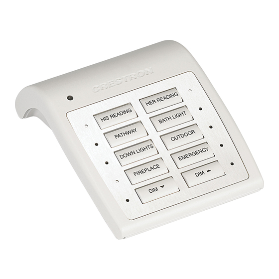
Description
The HTT-B10EX provides a simple, convenient wireless controller for lighting, home
automation, and entertainment in the home or of ce. Two-way in NET EX
operation supports true feedback, allowing lighting and security settings to be checked
and changed with con dence from any room. A clean array of 10 backlit push buttons with
individual feedback LEDs affords easy, tactile control of any custom function. The
HTT-B10EX is a fully programmable controller designed to operate as part of a complete
Crestron
®
automation system, communicating via the in NET EX wireless control network.
Additional Resources
Visit the product page on the Crestron website (www.crestron.com) or
scan the QR code to the right for additional information and the latest
rmware updates.
Button Installation
NOTES: Observe the following points.
• This product should be installed and used in accordance with appropriate electrical
codes and regulations.
• This product should be installed by a quali ed electrician.
The HTT-B10EX is shipped with 10 blank buttons (two columns of ve buttons). To replace
one or both button columns, follow this procedure:
1. Disconnect the 12 volt power pack and remove the batteries.
2. Remove the four Phillips screws from the four corners on the bottom of the unit.
3. Remove the faceplate from the front of the unit.
4. Remove the old button column(s) and replace it with the new one(s). Make sure the
column is seated in the two small holes on the side. No screws are required.
5. Replace the faceplate on the front of the unit.
6. Replace the four Phillips screws on the bottom of the unit.
7. Reinstall the batteries or reconnect the 12 volt power pack.
HTT-B10EX Button Installation
NOTE: The HTT-B10EX comes from the factory with a protective plastic overlay
installed to prevent scratches on the metal face. Remember to remove this overlay prior
to handing the product over to the customer.
®
wireless
®
Local Button Feedback
Local button feedback provides positive con rmation for a button press. When enabled,
the LED next to the pressed button lights for as long as the button is pressed. Use SIMPL
Windows to enable or disable local button feedback.
When local button feedback is disabled (default) in SIMPL Windows, all button feedback is
governed by the control system program.
Hardware Hookup
The only connection to the HTT-B10EX is for the included 12 volt power pack.
NOTE: The HTT-B10EX cannot charge rechargeable AA batteries.
When connecting the HTT-B10EX, consider the following:
• Use Crestron power supplies for Crestron equipment.
• The included cable cannot be extended.
Hardware Connections for the HTT-B10EX
12V 0.5A:
AC Power Pack
Wireless Communications
The device connects to the Crestron network via the in NET EX communications protocol.
Use the procedures outlined below to join or leave an in NET EX network and to verify
communications between the device and the control system.
Joining an in NET EX Network
Before a device can be used in a lighting system, it must rst join an in NET EX network
by being acquired by an in NET EX gateway.
NOTE: A device can be acquired by only one gateway.
1. Put the in NET EX gateway into Acquire mode from the unit itself or from Crestron
Toolbox™, as described in its manual at www.crestron.com/manuals.
NOTE: In an environment where multiple gateways are installed, only one
gateway should be in Acquire mode at any time.
2. Place the device into Acquire mode.
a. Tap either the left or right top buttons three times, and then press and hold it
down (tap-tap-tap-press+hold) until the corresponding LED on the device ashes
once (this can take up to 10 seconds).
b. Release the button to start the acquire process. The left or right top button LED
blinks slowly to show that the device is actively scanning the in NET EX network.
• The device is acquired when the left or right top button LED lights solid for 5
seconds and then turns off.
• If the acquire process fails, the left or right top button LED flashes rapidly. Tap
the left or right top button to acknowledge failure to acquire the infiNET EX
network. The LED times out automatically when under battery power. Ensure
gateway is in Acquire mode and within range before attempting the acquire
process again.
3. Once all devices have been acquired, take the gateway out of Acquire mode. Refer
to the gateway's operations guide for details.
Leaving an in NET EX Network
To leave an in NET EX network, put the device into Acquire mode, as described in
"Joining an in NET EX Network" above, when no gateway is in Acquire mode.
Verifying Communications Status
To check the communications status of the device, tap either the left or right top button
three times and then press and hold it down (tap-tap-tap-press+hold) for up to 2 seconds.
The left or right top button LED blinks to indicate the communications status. Refer to the
following table for details.
LED
Turns on for 5 seconds
Device is communicating with the control system.
Blinks three times
Device is communicating with the gateway but the
(12 volt operation only)
gateway is not communicating with the control system.
Blinks twice
Device was previously joined to the network but is not
communicating with the gateway.
Blinks once
Device is not joined to the network.
COMMUNICATIONS STATUS
Advertisement

Related Manuals for Crestron HTT-B10EX


Summary of Contents for Crestron HTT-B10EX
- Page 1 NOTE: A device can be acquired by only one gateway. HTT-B10EX Button Installation 1. Put the in NET EX gateway into Acquire mode from the unit itself or from Crestron Toolbox™, as described in its manual at www.crestron.com/manuals. NOTE: In an environment where multiple gateways are installed, only one gateway should be in Acquire mode at any time.
- Page 2 As of the date of manufacture, the HTT-B10EX has been tested and found to comply with equivalent isotropically radiated power (e.i.r.p.) is not more than that necessary for successful speci cations for CE marking.
Need help?
Do you have a question about the HTT-B10EX and is the answer not in the manual?
Questions and answers