
Subscribe to Our Youtube Channel
Related Manuals for Beckhoff CP9030


Summary of Contents for Beckhoff CP9030
- Page 1 Operating instructions for Beckhoff CP9030 / CP9035 CP-Link Cards Version: 1.5 Date: 2009-10-05...
-
Page 2: Table Of Contents
Boser HS6237 SBC Inside Technology 686LCD SBC MITAC 251 SBC Vampower 7 Graphic Card Vampower 8 Graphic Card View of the CP9030 Slot Cover CP9030 DPRAM Memory Allocation CP9030 card pin assignments Description of the Status LEDs Jumper Assignments ISA bus current consumption... - Page 3 General instructions CP9030 / CP9035...
-
Page 4: General Instructions
© This documentation is copyrighted. Any reproduction or third party use of this publication, whether in whole or in part, without the written permission of Beckhoff Automation GmbH, is forbidden. CP9030 / CP9035... -
Page 5: Beckhoff Cp-Link System Description
Beckhoff CP-Link System Description Beckhoff CP-Link System Description System LCD grafic- CP-Link CP-Link TFT display controller Control Panel multiplexer multiplexer ouch screen Motherboard - Keyboard PC keyboard - Serial interface CP-Link - Diskette drive PLC keys giga bit serial link... -
Page 6: Example: Cp-Link "Single" Connection
Beckhoff CP-Link System Description Example: CP-Link "Single" Connection One Control Panel with Touchpad and Touchscreen The signals required for the touchpad (RS232) and touchscreen (RS232) are distributed through connector ST303 to the computer's individual COM ports. The sequence of the COM ports only has to be maintained for the installation of the corresponding drivers. -
Page 7: Multi Cp-Link
Beckhoff CP-Link System Description Multi CP-Link Up to three Control Panels Up to three Control Panels can be connected to one PC. Each Control Panel can be installed at a distance of up to 100 m from the PC, which ensures maximum flexibility in locating the Control Panel on the equipment. -
Page 8: Example: Cp-Link "Double" Connection
Beckhoff CP-Link System Description Example: CP-Link "Double" Connection One Control Panel with Touchscreen and one Control Panel with Touchpad If we assume that the Control Panel with touchpad is connected to CP-Link 1 and that the Control Panel with touchscreen is connected to CP-Link 2,... -
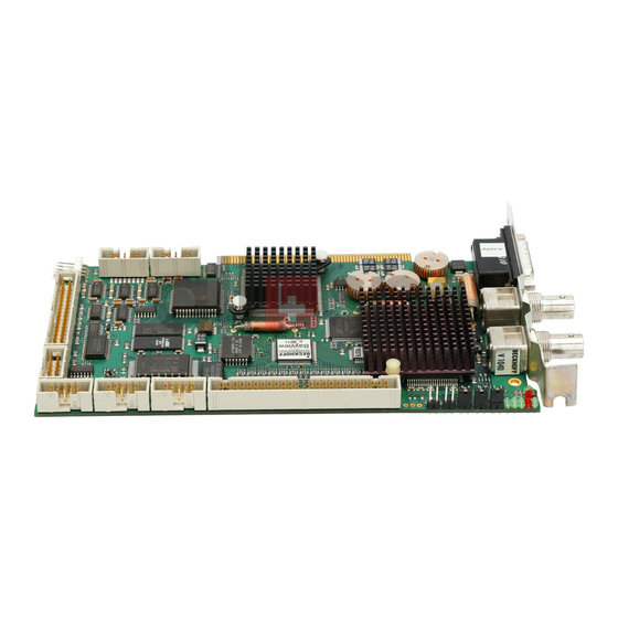
Page 9: Technical Data Cp9030
Technical Data CP9030 Technical Data CP9030 Layout of the BECKHOFF CP-Link Card CP9030_3 Fig. 5 CP9030 / CP9035... - Page 10 Technical Data CP9030 Configuration jumpers on the CP9030_3 Fig. 6 J249 J250 J247 J248 J245 J246 J243 J244 J241 J242 J239 J240 J237 J238 J235 J236 J233 J234 J231 J232 J229 J230 J227 J228 J225 J226 J223 J224 J221 J222...
- Page 11 Technical Data CP9030 CP9030_4 Fig. 7 CP9030 / CP9035...
- Page 12 Technical Data CP9030 Configuration jumpers on the CP9030_4 Fig. 8 J249 J250 J247 J248 J245 J246 J243 J244 J241 J242 J239 J240 J237 J238 J235 J236 J233 J234 J231 J232 J229 J230 J227 J228 J225 J226 J223 J224 J221 J222...
- Page 13 Technical Data CP9030 CP9030_5 Fig. 9 ST600 ST306 ST404 CP9030 / CP9035...
- Page 14 Technical Data CP9030 Configuration jumpers on the CP9030_5 Fig. 10 J249 J250 J247 J248 J245 J246 J243 J244 J241 J242 J239 J240 J237 J238 J235 J236 J233 J234 J231 J232 J229 J230 J227 J228 J225 J226 J223 J224 J221 J222...
-
Page 15: Cable And Jumper Configurations
Technical Data CP9030 Cable and jumper configurations Advantech SBC CLOSED J207, J208, J209, J210, J214, J239, J240, J245 LO100 (CP9030_4) for 15 inch display OPEN It is essential that the remaining jumpers are OPEN to avoid damaging the CP-Link card or the graphic card / SBC! Ribbon Cable ST205 (50 pin RM2.0) -
Page 16: Inside Technology 686Lcd Sbc
Technical Data CP9030 Inside Technology 686LCD SBC CLOSED J203, J209, J212, J214, J217, J220, J223, J226, J229, J232, J235, J238, J240, J245, J250 LO100 (CP9030_4) for 15 inch display OPEN It is essential that the remaining jumpers are OPEN to avoid damaging the CP-Link card or the graphic card / SBC! Ribbon Cable ST202 (50 pin RM2.54) -
Page 17: View Of The Cp9030 Slot Cover
Technical Data CP9030 View of the CP9030 Slot Cover Fig. 2 CP9030 / CP9035... -
Page 18: Cp9030 Dpram Memory Allocation
Technical Data CP9030 CP9030 DPRAM Memory Allocation Address Denomination BIT 7 BIT 6 BIT 5 BIT 4 BIT 3 BIT 2 BIT 1 BIT 0 0x03FF Request Active Toggle 0x03FE Ready COM_F Toggle 0x03FD ..Ident String „CP9030 v1.730“ 0x03F0... - Page 19 Technical Data CP9030 LED1..256 Output for LEDs; "1" = LED on Up to 256 LEDs can be controlled BUTTON1..256 Inputs for buttons; "1" = button pressed Up to 256 buttons can be read No. of pd outp. words (number of process data output words) A reference value with which the output status derived from the Control Panel (CP2020 pd outp.words) is compared.
- Page 20 Technical Data CP9030 Control BLOFF : "1" switches the background illumination off Keyb_on : "1" disables the Control Panel's membrane keypad J300 (CP9030_3) J501 and J502 must be set Ident String Returns the current firmware status of the CP-Link card...
-
Page 21: Cp9030 Card Pin Assignments
HSYNC VSYNC DISPCLK IC201 indicates the programmed graphic card adaptation and its version. IC500 indicates the revision of the BECKHOFF firmware for the CP-Link card. ST305 (Keyboard switching for the next CP-Link card) Signal Signal PCKCI PCKDI ST304 (External keyboard connection) - Page 22 Technical Data CP9030 ST203, ST600 (FDD connection for the Control Panel) Signal Signal Signal DENSEL MTR1 WRTPRT RDATA INDEX STEP HDSEL WDATA DSKCHG WGATE ST501 (24V UPS control) Signal Signal PCL0 PCL1 PCH0 PCH1 ST302 (Touchscreen connection)* Signal Signal ST301 (Touchpad/RS232 connection)
- Page 23 Technical Data CP9030 ST303 external connection ST303 RS232 Touchscreen Keyboard Keyboard Mouse D-SUB 9 D-SUB 9 DIN 5 PS/2 PS/2 female* female * The RS232 and Touchpad connections are identical CP9030 / CP9035...
- Page 24 Technical Data CP9030 SW500 (Index setting) Signal ON DIP 2 3 4 SW400 (Address setting) Segment C800 1 2 3 4 5 6 7 8 C880 C900 "1"=ON - "0"=OFF C980 CA00 CA80 CB00 CB80 CC00 CC80 CD00 CD80 CE00...
-
Page 25: Description Of The Status Leds
If the LED is lit, the clock signal from the video card is present. If it is not lit, then either the video card is not operating correctly, or the connection of the video card to the CP9030 is not made properly. LED 03 - Receive PLL locked If the LED is lit, data are being sent from the Control Panel to the PC. -
Page 26: Jumper Assignments
JU402 to be set. Do not change any of the factory settings without first contacting our Technical Support. ISA bus current consumption The CP9030 card is powered primarily from the PC's ISA bus. At larger distances (> 50 m) it is recommended that the additional power supply connection, ST404, is used. -
Page 27: Technical Data Cp9035
Technical Data CP9035 Technical Data CP9035 Layout of the BECKHOFF CP-Link Card CP9035_1 Fig. 11 CP9030 / CP9035... - Page 28 J234 J233 J232 J231 J230 J229 J228 J227 J226 J225 J224 J223 J222 J221 J220 J219 J218 J217 J216 J215 J214 J213 J212 J211 J210 J209 J208 J207 J206 J205 J204 J203 J202 J201 BECKHOFF CP9035_ 1 CP9030 / CP9035...
-
Page 29: Cable And Jumper Configurations
Technical Data CP9035 Cable and jumper configurations The jumper and cable configurations are compatible with the CP9030 ISA version. CP9035 card pin assignments ST202 [RM2.54] / ST204 [RM2.0] – display connection The assignment varies according to the programming. Signal Signal... - Page 30 ST600 (FDD connection for the Control Panel) Signal Signal Signal DENSEL MTR1 WRTPRT RDATA INDEX STEP HDSEL WDATA DSKCHG WGATE ST501 (24V UPS control) Signal Signal PCL0 PCL1 PCH0 PCH1 ST302 (Touchscreen connection)* Signal Signal ST301 (Touchpad/RS232 connection) Signal Signal CP9030 / CP9035...
- Page 31 Technical Data CP9035 ST401 (Voltage connection for the CP-Link card) Signal ST303 external connection ST303 RS232 Touchscreen Keyboard Keyboard Mouse D-SUB 9 D-SUB 9 DIN 5 PS/2 PS/2 female* female * The RS232 and Touchpad connections are identical CP9030 / CP9035...
-
Page 32: Description Of The Status Leds
If the LED is lit, the clock signal from the video card is present. If it is not lit, then either the video card is not operating correctly, or the connection of the video card to the CP9030 is not made properly. LED 102 - Receive PLL locked If the LED is lit, data are being sent from the Control Panel to the PC. -
Page 33: Jumper Assignments
The CP9035 card is powered exclusively through the ST401 power supply connector. It cannot be powered via the PCI bus - this could damage the motherboard. Current consumption 5V: approx. 1.0 A Current consumption 12V: approx. 1.5 A CP9030 / CP9035... -
Page 34: View Of The Cp9035 Slot Cover
Technical Data CP9035 View of the CP9035 Slot Cover Fig. 13 CP9030 / CP9035... -
Page 35: Technical Data Cp9035 With Dvi-Add Card
Connect power supply Take care that the connectors ST101 and ST401 are connected to the Note power supply. ST101 and ST401 are connected via a Y-cable, which is included in delivery. The LED 100 indicates the correct power supply. CP9030 / CP9035... -
Page 36: Multi Cp-Link Cable-Sets
One multi CP-Link cable set is needed to connect multiple Control Panel to a PC. Multi CP- Cable sets for installation of multiple CP-Link-Interface cards Link CP9030 into one PC C9900-K240 cable set for multi CP-Link for installation of 2 CP-Link interface cards CP903x into C6140, C6150, C6240, C6250 or other PCs... -
Page 37: Cp-Link Connecting Cable
2 cables included C9900-K126 CP-Link cable set with BNC connectors – length 100 m (for easy installation at the PC and the mounting arm: 1 m Aircell7 + 91 m Cellflex + 8 m Aircell7), 2 cables included CP9030 / CP9035... - Page 38 – length 15 m (cable type RG214 HIFLEX, bending radius 35 mm), 2 cables included C9900-K144 CP-Link cable set with BNC connectors, suitable as trailing cable – length 20 m (cable type RG214 HIFLEX, bending radius 35 mm), 2 cables included CP9030 / CP9035...
Need help?
Do you have a question about the CP9030 and is the answer not in the manual?
Questions and answers