Table of Contents
Advertisement
Quick Links
Advertisement
Table of Contents

Related Manuals for Beckhoff CX2550-0010


Summary of Contents for Beckhoff CX2550-0010
- Page 1 Manual CX2550-0010 Extension module for CX2000 Version: Date: 2016-08-31...
-
Page 3: Table Of Contents
5.3.3 Deactivating the Disk Defragmenter service .............. 24 Setting up a RAID system...................... 25 5.4.1 Using the Beckhoff USB stick for setting up the system .......... 26 5.4.2 Using the Intel Manager for setting up the system............ 27 5.4.3 Replacing storage media .................... 30 5.4.4... - Page 4 Table of contents Version: 1.1 CX2550-0010...
-
Page 5: Foreword
EP0851348, US6167425 with corresponding applications or registrations in various other countries. ® EtherCAT is registered trademark and patented technology, licensed by Beckhoff Automation GmbH, Germany Copyright © Beckhoff Automation GmbH & Co. KG, Germany. The reproduction, distribution and utilization of this document as well as the communication of its contents to others without express authorization are prohibited. -
Page 6: Safety Instructions
All the components are supplied in particular hardware and software configurations appropriate for the application. Modifications to hardware or software configurations other than those described in the documentation are not permitted, and nullify the liability of Beckhoff Automation GmbH & Co. KG. Personnel qualification This description is only intended for trained specialists in control, automation and drive engineering who are familiar with the applicable national standards. -
Page 7: Documentation Issue Status
Foreword Documentation issue status Version Modifications First version Chapter Recovery mode added CX2550-0010 Version: 1.1... -
Page 8: Product Overview
When components are being fitted or removed, the supply voltage must be switched off. Software knowledge System malfunctions Mandatory software knowledge! Every user must be familiar with any of the functions of the software installed on the PC that he can reach. Attention Version: 1.1 CX2550-0010... -
Page 9: System Overview
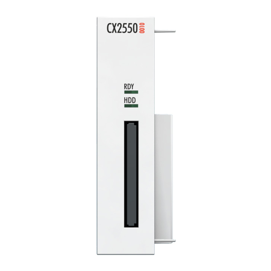
The internal SATA-6G-Port also offers sufficient bandwidth for the latest SSD storage media. The CX2550-00100 extension module has a CFast slot for CFast cards. Up to two CX2550-0010 CFast modules can be connected, so that a total of up to three CFast slots are available. -
Page 10: Cx2550-0010 - Technical Data
Product overview CX2550-0010 - Technical data Dimensions Technical data Technical data CX2550-0010 Interfaces SATA Connection type CFast slot Power supply via system bus (through CX2100-0xxx power supply modules) Dimensions (W x H x D) 24 mm x 99 mm x 91 mm Weight approx. -
Page 11: Unpacking And Transport
5. Check the contents for visible shipping damage. 6. If you notice any shipping damage or inconsistencies between the contents and your order, you should notify Beckhoff Service. Shipping and relocation Despite the robust design of the unit, the components are sensitive to strong vibrations and impacts. -
Page 12: Installing The Extension Module
1. Put a screwdriver into the recess on the short side of the protective cap and lever it off. 2. Remove the protective cap to expose the bus connector. 3. If a power supply unit is already connected, remove it from the basic CPU module. Version: 1.1 CX2550-0010... - Page 13 5. The module clicks into the basic CPU module and the power supply unit. ð The extension module has been installed successfully, if the individual modules were connected straight and flush. Next, you can install the bar clips, thereby reinforcing interlocking of the modules. CX2550-0010 Version: 1.1...
-
Page 14: Installing The Bar Clips
ð The bar clips have been installed successfully, if they don't protrude and are level with the cooling fins of your modules. Once all extension modules are locked, the whole assembly can be installed on the mounting rail. Version: 1.1 CX2550-0010... -
Page 15: Installation On The Mounting Rail
The images below show the permitted and two unacceptable installation positions: Incorrect installation positions The CX20x0 system must not be operated vertically on the DIN rail. This installation position provides insufficient ventilation for the devices. In horizontal position the devices are not sufficiently ventilated either. CX2550-0010 Version: 1.1... - Page 16 The CX20x0 can easily be installed on the mounting rail. The housing is designed such that it can be pushed against the mounting rail and engaged on it. Install the devices on the mounting rail as follows: 1. Unlock the latches at the top and bottom. Version: 1.1 CX2550-0010...
- Page 17 3. Then lock the latches again. ð The devices are now installed successfully. Verify that the devices are installed correctly and that all devices are engaged on the mounting rail. In the next step you can commission the devices. CX2550-0010 Version: 1.1...
-
Page 18: Commissioning
Once the software has been stopped, the operating system can be shut down. Only then should the power supply be interrupted. If the electricity supply for the power supply unit is switched off, the basic CPU module and the extension module are also switched off. Version: 1.1 CX2550-0010... -
Page 19: Installing And Removing Cfast Cards
Save your data and switch off the devices before you install or remove storage media. Note The extension module CX2550-0010 expands the basic CPU module and makes additional CFast slots available. The CX2550-0010 extension modules can be used for additional storage media to provide additional memory or to set up a RAID system. -
Page 20: Partitioning Storage Media
These instructions are intended for Embedded PCs and Industrial PCs with the Windows Embedded Standard (WES) 7 operating system or higher. The following sections contain further information on: • activating the Windows Disk Defragmenter service and • partitioning of your storage media. Version: 1.1 CX2550-0010... -
Page 21: Activating The Disk Defragmenter Service
3. Double-click on Disk Defragmenter. The Disk Defragmenter Properties window appears. 4. Under Startup type select the option Automatic and click OK. ð The Disk Defragmenter service is now enabled. In the next step you can partition a storage medium. CX2550-0010 Version: 1.1... -
Page 22: Partitioning
2. Click on Administrative Tools, then Computer Management. The Computer Management window appears. 3. In the tree view click on Disk Management. The installed storage media are displayed. 4. Right-click on a storage medium, then click on Shrink Volume in the context menu. Version: 1.1 CX2550-0010... - Page 23 ð You have now successfully partitioned a storage medium. The new storage medium appears next to the reduced storage medium. Be sure to disable the Disk Defragmenter service after the partitioning, so that this function is not available to unauthorized users. CX2550-0010 Version: 1.1...
-
Page 24: Deactivating The Disk Defragmenter Service
2. Click on Administrative Tools, then Services. The Services window opens. 3. Double-click on Disk Defragmenter. The Disk Defragmenter Properties window appears. 4. Under Startup type select the option Disabled and click OK. ð The Disk Defragmenter service is now disabled. Version: 1.1 CX2550-0010... -
Page 25: Setting Up A Raid System
• Using a Beckhoff USB stick with integrated Beckhoff Service Tool (see: Using the Beckhoff USB stick for setting up the system [} 26]). • Using the Intel Manager, which is pre-installed on your device. This method has the advantage that the image does not have to be reinstalled (see: Using the Intel Manager for setting up the system [} 27]). -
Page 26: Using The Beckhoff Usb Stick For Setting Up The System
Save your data before continuing. Note With this method the RAID system is set up with the aid of a Beckhoff USB stick. The data on the storage medium is mirrored to a second storage medium, which enhances the data security. -
Page 27: Using The Intel Manager For Setting Up The System
• At least two storage media have to be installed in the device. How to set up a RAID system with the Intel Manager: 1. Start the Intel Manager under Start > All Programs > Intel > Intel Rapid Storage Technology. 2. In the toolbar click on Create. CX2550-0010 Version: 1.1... - Page 28 2. Select the option Yes: Disk on port 2 to determine which storage medium is to be mirrored. The option Disk on port 2 matches the system drive C:, on which the image is installed. 6. Click on Next. Version: 1.1 CX2550-0010...
- Page 29 ð The RAID system is created. The Intel Manager changes to status view and shows the newly created RAID system and the storage media used. In addition, the progress of the data migration to the second storage medium is displayed in percent. CX2550-0010 Version: 1.1...
-
Page 30: Replacing Storage Media
The new storage medium, which was installed as replacement, is shown below. 2. Click on Rebuild to another disk to integrate the new storage medium in the RAID system. Version: 1.1 CX2550-0010... - Page 31 Commissioning 3. Select the option Disk on port 0 and click on Rebuild. ð You have successfully replaced a damaged storage medium and restored the RAID system. The progress of the restoration is indicated in percent. CX2550-0010 Version: 1.1...
-
Page 32: Deleting A Raid System
3. Click on Yes to acknowledge the warning. ð The RAID system was deleted successfully. The storage media are displayed individually in the status overview of the Intel Manager and are no longer part of a RAID system. Version: 1.1 CX2550-0010... -
Page 33: Using The Recovery Mode
1. Start the Intel Manager under Start > All Programs > Intel > Intel Rapid Storage Technology. 2. In the toolbar click on Create. 3. Under Select Volume Type select the option Flexible data protection (Recovery). 4. Click on Next. CX2550-0010 Version: 1.1... - Page 34 Recovery system and the storage media used. In addition, the progress of the data migration to the Recovery storage medium is displayed in percent. Klick on Update data to manually copy data from master to the recovery storage media. Version: 1.1 CX2550-0010...
-
Page 35: Error Handling And Diagnostics
6. Any components / software used The quickest response will come from support / service in your country. Therefore please contact your regional contact. For details please refer to our website at www.beckhoff.de or ask your distribution partner. CX2550-0010 Version: 1.1... -
Page 36: Removal And Disposal
2. Remove the wiring from the first terminal next to the power supply unit. 3. Pull the orange tab to remove the terminal. 4. Release the DIN rail mounting by pushing the latches outwards with a screwdriver. Version: 1.1 CX2550-0010... - Page 37 Once the bar clips have been removed successfully, the modules can be separated from each other. Disposal The device must be fully dismantled in order to dispose of it. Electronic components must be disposed of according to national electronic waste regulations CX2550-0010 Version: 1.1...
-
Page 38: Appendix
All products of the Embedded PC family are CE, UL and GOST-R certified. Since the product family is continuously developed further, we are unable to provide a full listing here. The current list of certified products can be found at www.beckhoff.com. FCC Approvals for the United States of America... -
Page 39: Support And Service
Beckhoff's branch offices and representatives Please contact your Beckhoff branch office or representative for local support and service on Beckhoff products! The addresses of Beckhoff's branch offices and representatives round the world can be found on her internet pages: http://www.beckhoff.com You will also find further documentation for Beckhoff components there.
Need help?
Do you have a question about the CX2550-0010 and is the answer not in the manual?
Questions and answers