Table of Contents
Advertisement
Quick Links
Advertisement
Table of Contents

Related Manuals for Beckhoff CX2500-0061


Summary of Contents for Beckhoff CX2500-0061
- Page 1 Manual CX2500-0061 Power over Ethernet (PoE) module Version: Date: 2016-07-13...
-
Page 3: Table Of Contents
Documentation issue status...................... 5 2 Product overview............................ 6 Intended use ............................. 6 System overview.......................... 7 CX2500-0061 - Technical data ...................... 8 3 Unpacking and transport .......................... 9 4 Mounting and wiring .......................... 10 Installing at the CX20x0 system ..................... 10 Installing the bar clips ........................ 12 Installation on the mounting rail ...................... -
Page 4: Foreword
EP0851348, US6167425 with corresponding applications or registrations in various other countries. ® EtherCAT is registered trademark and patented technology, licensed by Beckhoff Automation GmbH, Germany Copyright © Beckhoff Automation GmbH & Co. KG, Germany. The reproduction, distribution and utilization of this document as well as the communication of its contents to others without express authorization are prohibited. -
Page 5: Safety Instructions
All the components are supplied in particular hardware and software configurations appropriate for the application. Modifications to hardware or software configurations other than those described in the documentation are not permitted, and nullify the liability of Beckhoff Automation GmbH & Co. KG. Personnel qualification This description is only intended for trained specialists in control, automation and drive engineering who are familiar with the applicable national standards. -
Page 6: Product Overview
When components are being fitted or removed, the supply voltage must be switched off. Software knowledge System malfunctions Mandatory software knowledge! Every user must be familiar with any of the functions of the software installed on the PC that he can reach. Attention Version: 1.0 CX2500-0061... -
Page 7: System Overview
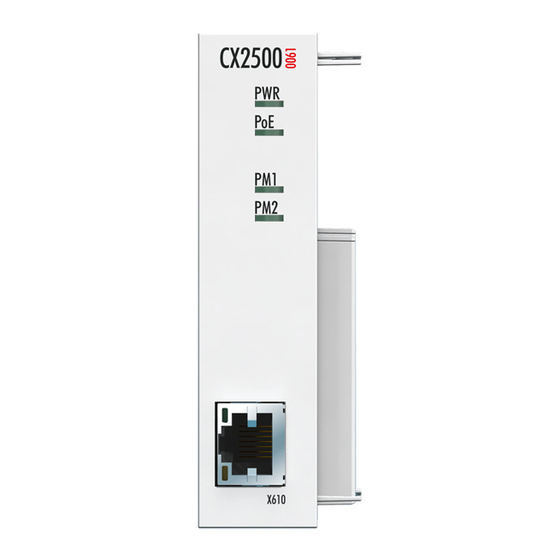
Power over Ethernet (PoE) module CX2500-0061 The CX2500-0061 Power over Ethernet module supports devices with PoE class 0, 1, 2, 3 and 4 in accordance with the PoE standard IEEE 802.3af-2003. The maximum PoE power output is 15.4 W. The PoE supply voltage is generated internally, no external power supply is necessary. -
Page 8: Cx2500-0061 - Technical Data
Product overview CX2500-0061 - Technical data Dimensions The system module CX2500-0061 provides a further Power over Ethernet (PoE) interface for the CX20x0. Technical data CX2500-0061 Interfaces 1 x RJ45, 10/100/1000 MBit/s with Power-over-Ethernet (PoE) max. PoE power delivery 15,4 W... -
Page 9: Unpacking And Transport
5. Check the contents for visible shipping damage. 6. If you notice any shipping damage or inconsistencies between the contents and your order, you should notify Beckhoff Service. Shipping and relocation Despite the robust design of the unit, the components are sensitive to strong vibrations and impacts. -
Page 10: Mounting And Wiring
1. Put a screwdriver into the recess on the short side of the protective cap and lever it off. 2. Remove the protective cap to expose the bus connector. 3. Insert the system module on the left-hand side of the basic CPU module. Version: 1.0 CX2500-0061... - Page 11 4. The module clicks into the basic CPU module. ð The system module has been installed successfully, if the individual modules were connected straight and flush. Next, you can install the bar clips, thereby reinforcing interlocking of the modules. CX2500-0061 Version: 1.0...
-
Page 12: Installing The Bar Clips
ð The bar clips have been installed successfully, if they don't protrude and are level with the cooling fins of your modules. Once all fieldbus modules are locked, the whole assembly can be installed on the mounting rail. Version: 1.0 CX2500-0061... -
Page 13: Installation On The Mounting Rail
The images below show the permitted and two unacceptable installation positions: Incorrect installation positions The CX20x0 system must not be operated vertically on the DIN rail. This installation position provides insufficient ventilation for the devices. In horizontal position the devices are not sufficiently ventilated either. CX2500-0061 Version: 1.0... - Page 14 The CX20x0 can easily be installed on the mounting rail. The housing is designed such that it can be pushed against the mounting rail and engaged on it. Install the devices on the mounting rail as follows: 1. Unlock the latches at the top and bottom. Version: 1.0 CX2500-0061...
- Page 15 3. Then lock the latches again. ð The devices are now installed successfully. Verify that the devices are installed correctly and that all de- vices are engaged on the mounting rail. In the next step you can commission the devices. CX2500-0061 Version: 1.0...
-
Page 16: Ethernet Interface (X610)
(X610). The required voltage is generated internally in the CX2500-0061 system module. An external power supply unit is not necessary. Devices that are not PoE-capable can also be connected to the Ethernet interface (X610). The CX2500-0061 system module checks connected devices before the start and tests them for their PoE capability. -
Page 17: Error Handling And Diagnostics
The LED flashes if data traffic takes place. SPEE Indicates the connection green The LED is green if the speed is 10 or 100 speed. Mbit. In 1000 Mbit mode (Gigabit) the LED is red. CX2500-0061 Version: 1.0... -
Page 18: Faults
6. Any components / software used The quickest response will come from support / service in your country. Therefore please contact your regional contact. For details please refer to our website at www.beckhoff.de or ask your distribution partner. Version: 1.0... -
Page 19: Removal And Disposal
2. Remove the wiring from the first terminal next to the power supply unit. 3. Pull the orange tab to remove the terminal. 4. Release the DIN rail mounting by pushing the latches outwards with a screwdriver. CX2500-0061 Version: 1.0... - Page 20 Once the bar clips have been removed successfully, the modules can be separated from each other. Disposal The device must be fully dismantled in order to dispose of it. Electronic components must be disposed of according to national electronic waste regulations Version: 1.0 CX2500-0061...
-
Page 21: Appendix
All products of the Embedded PC family are CE, UL and GOST-R certified. Since the product family is continuously developed further, we are unable to provide a full listing here. The current list of certified products can be found at www.beckhoff.com. FCC Approvals for the United States of America... -
Page 22: Support And Service
Beckhoff's branch offices and representatives Please contact your Beckhoff branch office or representative for local support and service on Beckhoff products! The addresses of Beckhoff's branch offices and representatives round the world can be found on her internet pages: http://www.beckhoff.com You will also find further documentation for Beckhoff components there.
Need help?
Do you have a question about the CX2500-0061 and is the answer not in the manual?
Questions and answers