
Related Manuals for XCMG XE17U

Summary of Contents for XCMG XE17U
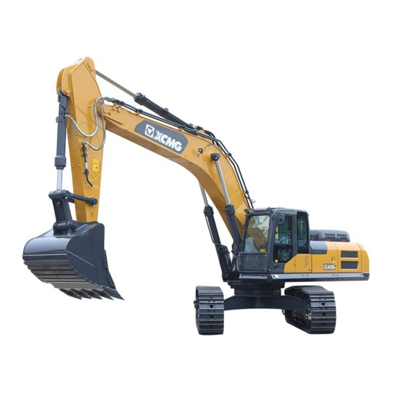
- Page 1 XUZHOU XCMG EXCAVATOR MACHINERY CO., LTD. Hydraulic Excavator XE17U Instructions Manual ( EN ) Subject to technical modifications Original status: 2020-07...
- Page 2 The overload warning system of the lifting operation is optional. If the machine is used for lifting, please contact your XCMG dealer, and confirm whether the system has been installed. If not, it is forbidden to use it for lifting. Otherwise, any accident occurred has no responsibility with XCMG.
- Page 3 Hydraulic Excavator XE17U EC Declaration of Conformity Xuzhou XCMG Excavator Machinery Co., Ltd. No.39 Gaoxin Road, Economic and Technological Development Zone, Xuzhou, Jiangsu 221004, P.R. China Hereby declares that the product: Product name: XCMG Zero Tail Excavator Model: XE17U Serial number (PIN):...
- Page 4 XCMG's key to unlocking global markets. XUZHOU XCMG EXCAVATOR MACHINERY CO., LTD., as the core pillar of XCMG, is a new “fist” enterprise that XCMG strives to build. It is committed to providing customers with the best solutions of construction machinery.
-
Page 5: Table Of Contents
Hydraulic Excavator XE17U Table of Content: 1 User Guide ..........................1 1.1 Key groups of users ......................1 1.2 Setup of User’s Instructions .................... 2 Safety Notes ....................... 2 Tips, Hints, Recommendations ................2 ... - Page 6 Hydraulic Excavator XE17U Fire ........................24 2.8 Safety Signs and Labels ....................26 Mandatory Signs ....................26 Prohibition Signs ....................27 Warning Signs ....................28 Rescue Signs ....................29 ...
- Page 7 Hydraulic Excavator XE17U 4.7 Electrical Schematic Diagram ..................65 4.8 Part identification and name plates ................65 Nameplate – Serial Number................66 Engine ....................... 66 Hydraulic Travel Motor ..................66 ...
- Page 8 Hydraulic Excavator XE17U 5.4 Control Lever ......................... 97 Control Stand – Cabin Overview ............... 97 Working Control ....................97 Dozer Lever Control Function ................99 Boom Deflection Pedal ..................99 ...
- Page 9 Hydraulic Excavator XE17U Fuel Tank ......................153 Water Separator ..................... 153 Fuel Filter ......................155 6.10 Maintenance of Clean Air System ................156 Air Cleaning Filter ................... 156 6.11 Maintenance of Engine Cooling System ..............157 ...
- Page 10 Hydraulic Excavator XE17U 12 Decommissioning and disposal ..................196 12.1 Properly disassemble the unit ..................196 12.2 Disposal........................196 09.2020 Seite X...
-
Page 11: User Guide
To ensure the documentation is always complete, up to date and close to the respective machine: – Do not remove individual pages from the instruction for use. – Request any missing or uncomprehensive parts of the instruction for use from XCMG after sales service. – Include new documents supplied as a result of modifications immediately. -
Page 12: Setup Of User's Instructions
Setup of User’s Instructions Safety Notes 1.2.1.1 Setup of Safety Notes Warning signs are structured as follows: Signal word 1. Kind and source of hazard (hazard’s gravity) 2. Possible consequences of ignoring the warning 3. Measures/precautions to take to avoid/prevent the hazard 1.2.1.2 Graduation of the Safety Notices Safety notices vary with decreasing hazard gravity as follows: Danger! -
Page 13: Product Description
Position lines in an image end with: o A dot, if they denote visible parts, o An arrow when pointing towards invisible/indicated direction Information such as left/right and front/rear refers to the seating position of the operator in the driver's cabin with the spraygun pointing backwards. -
Page 14: Intended Use
The EU declaration of conformity, in its present version and language, is valid in all countries of the European Union, as well as in countries that recognize the guideline 2006/42/EU. Additional documents such as prototype testing reports or international testing approvals shall also be part of the technical documentation file. -
Page 15: Special Modes Of Operation
– All safety instructions in this instruction for use must be observed during use – All valid national and international safety regulations to be observed – Only the operating materials listed in the instruction for use must be used – All persons involved in the machine’s operation must follow the safety instructions according to the instruction for use. -
Page 16: Space Boundaries
– Predictable misuse – Various steps within product lifecycle (assembly, commissioning/delivery, set up, regular operation, cleaning, maintenance & servicing, appropriate disposal) – Operator’s skills, experience and knowledge Operator, maintenance personnel in terms of training, experience, skills – Inexperienced/more vulnerable people o Vulnerable groups (e.g. -
Page 17: Reasonably Foreseeable Misuse
Reasonably Foreseeable Misuse "Reasonably foreseeable misuse" means the use of machinery in a way not prescribed in the instruction for use, but which may result from readily predictable human behaviors This includes any undeclared application or type of misuse listed in the Machine Directive (2006/42/EG). –... - Page 18 – Transport of persons along with the load or with equipment not intended for this purpose. – Lifting of persons with inadequate equipment or for unintended purposes – Lifting of other devices on/beneath which persons are located. – Lifting of loads attached to several lifting devices without considering the load limits defined in the instruction for use –...
-
Page 19: Safety And Hazards
2 Safety and Hazards Safety instructions are provided to prevent personal injury or property and/or environment damage. This chapter deals with the following issues: Responsibilities of participants: users, operators, drivers, support and maintenance staff PPE Risk of injuries ... -
Page 20: Detailed Tasks And Responsibilities
Detailed tasks and responsibilities The manufacturer is responsible for the technical safety of the machine and its accessories. ensures operational readiness of the machine and its accessories supervises the product’s performance in all periods of its life cycle ... -
Page 21: The Owner
consults with the manufacturer or their authorized representative before making any modification to the machine uses original XCMG spare parts only – as given in the spare part lists The operator ensures that only trained personnel operate or service the machine. -
Page 22: The Driver
Informs the operator of any safety-related changes/modifications on the machine. Performs modifications on the machine only after consulting the manufacturer. uses original XCMG spare parts only Additional requirements for this position: Qualifications and skills of the maintenance technician: ... -
Page 23: General Requirements For All Responsible Parties
General requirements for all responsible parties The operating personnel needs to: o Be physically and mentally suitable to operate the machine. This includes: o Good eyesight and hearing o Good spatial perception o Physical capacity o Good reflexes o Craftsmanship o Be qualified by appropriate training and instructions for operating the machine. -
Page 24: Hazards And Risks Of Injury
Hazards and Risks of Injury Before putting the machine into operation, check the following: o Machine indications and safety are not reporting any fault or warning o Driving machine work correctly o When loading the machine, make sure that nobody is coming under the lifted load. During operation, observe the followings: ... - Page 25 - Wipe any spilled diesel fuel off the machine - Neutralise spillages on the ground with bonding agents - Do not clean the machine with flammable fluids. - Do not store any cleaning cloths in the engine compartment and remove flammable residues, e.g.
-
Page 26: Lightning Strike
- Slowly move the slewing gear and observe any unusual noise or behaviour. - Start to move the boom and buckle and observe any unusual noise or behaviour Inspect the boom and buckle for damage. Contact XCMG for after-sales service. First Aid Measures –... -
Page 27: Injury From Mechanical Parts
- Never attempt to locate the leakage point with your hand or other parts of the body - Damaged hydraulic components must be replaced immediately with original XCMG spares - Check all hydraulic lines regularly (at least once a year) for damages and leaks - Replace damaged hydraulic lines immediately ... - Page 28 Contact with hot surfaces and consumables! High surface and equipment temperatures can lead to burns or scalding. Observe handling-specific and situation-specific safety notes. Observe the following safety notes: - Always wear suitable protective gloves when working on hot components. - Only carry out work on the machine after it has cooled down and is stopped.
-
Page 29: Chemical Burns
Chemical Burns Warning Contact with corrosive and chemical consumables! Acids and bases cause chemical burns to skin and tissue, and blindness if they come in contact with the eyes. Acids and bases will damage clothing. Observe handling-specific and situation-specific safety notes. ... -
Page 30: Environmental Risk
Inadequate ventilation or fresh air! - Poisonous vapours or other atmospheres hazardous to health can lead to poisoning or suffocation. Observe handling-specific and situation-specific safety notes. Observe the following safety notes: - Only operate machine in well-ventilated areas - Ensure adequate ventilation in the cabin. -
Page 31: Safety Distance To Overhead Power Lines Above Cabin
Safety distance to overhead power lines above cabin Treat the overhead power lines as live until shutoff has been confirmed in writing by the responsible authority. Pay attention to distances between overhead lines and spray beam. Break off if in doubt. Fig. -
Page 32: Safety Distance To Underground Power Lines/Water Supply
Safety distance to underground power lines/water supply Start working only after explicit approval or confirmation of the shutoff of the underground power supply lines by the responsible authority. Treat the underground power lines as live until shutoff has been confirmed in writing by the responsible authority. - Page 33 22 KV 3.0m 66 KV 4.0m 154 KV 5.0m 187 KV 6.0m 275 KV 7.0m 500 KV 11.0m First Aid Measures 1. Protection/personal safety • Identify - what kind of emergency? • Think - what dangers are there for the injured or helper? •...
-
Page 34: How To Act In Dangerous Situations
How to act in dangerous situations In the event that current is conducted to the machine from coming into contact with a power line, the current is distributed from the point of entry in the earth. The voltage decreases according to a funnel-shaped curve - a resistance area is formed. The machine contacts with the power supply line First response –... - Page 35 – Fire extinguishers are subject to national regulations! Take fire extinguishers on the machine off the holders Make it ready for operation. Fight the source of the fire with several short bursts. While fighting the fire, ask personnel to alert the fire brigade. First Aid 1.
-
Page 36: Safety Signs And Labels
If any safety sign is missing/damaged, contact Xuzhou XCMG Excavator Machinery Co. Ltd. immediately to have them replaced. – Do not hesitate to contact an XCMG agent for any other ambiguity or issue as well Mandatory Signs General mandatory action signs... -
Page 37: Prohibition Signs
Prohibition Signs A “prohibition sign” means a safety sign prohibiting behaviour likely to cause a risk to health or safety. Common prohibition signs Description Prohibition Signs Description Smoking forbidden Fire, open ignition sources and smoking are forbidden Pedestrians forbidden Forbidden for ground conveyors Access for persons with No access for unauthorized pacemakers or implanted... -
Page 38: Warning Signs
Warning Signs Warning signs indicate risks or hazards (ISO 7010) Common warning signs Description Warning Sign Description Warning of non-ionizing radiation Warning of obstacles on the ground Warning of fall hazard Warning of slipping hazard Warning of electric voltage Warning of suspended loads Warning of hot surfaces Warning of automatic start Warning of crushing hazard... -
Page 39: Rescue Signs
Rescue Signs Rescue signs mark the locations of first aid equipment and emergency exits. Description Rescue sign Description First aid Place where to find a first aid kit or simillar Emergency exit (door) Door useable to exit in case of emergency (alarm may turn on when opened;... -
Page 40: Machinery Specific Signs And Labels
Machinery Specific Signs and Labels Specifically Designed Warning Signs Sign Design Sign Description Danger! - high voltage Bringing the machine too close to power supply lines may cause electric shocks Keep it at a safe distance from power lines when operating/driving a machine Warning! - risk of injury due to improper window fixing Opening the front window may result in falling out of the machine Be sure to lock the windows properly with designated pins when opening them... - Page 41 Do not stick your hand or head out of the cabin window during machine operation. Prohibition to use high-pressured water or steam to clean the machine Risk of electric shocks and irreversible damage through shortcut Do not use water or steam sprayers to clean the machine (even outer parts) Warning! –...
- Page 42 Caution! – Unstable area There is risk to trip and fall in this area Standing in this area is prohibited to prevent injuries Warning! – working area of a moving boom You may collide with the machine’s device inside of its moving scope Keep a safe distance from the boom while it is operated.
-
Page 43: Specific Designed Signs For Functions And Operation
Read and comprehend all safety information contained in this manual and the safety symbols related to the machine. Keep safety symbols in good condition; if any is missing or damaged, replace it immediately. If you have any question, contact an XCMG agent or Xuzhou XCMG Excavator Machinery Co. Ltd. -
Page 44: Safe Operation Of Machine
3 Safe Operation of Machine Safety for Children Children are normally attracted to machines and their operation.If children are in the vicinity of the machine and are not at a suitable distance and in the field of vision of the operator, this can lead to serious accidents or even death of the children. -
Page 45: Safety Rules
Safety Rules Notice – When servicing the machine, do not use any worn-out/damaged tools to prevent injuries or unsatisfactory maintenance. – Check the fire extinguisher regularly and exchange/refill them if needed. – Ensure effective emergency training of all field personnel. –... - Page 46 Handrails and steps To avoid injury when climbing up and down the machine, use the handrails and steps marked by the triangular arrows in the drawing below. To ensure safe boarding: – Always face the machine while boarding or leaving it. –...
-
Page 47: Pre-Inspections And Safety
Pre-inspections and Safety Warning! Never start the engine/touch any part of the machine: 1. during maintenance/service by other personnel or 2. when a warning sign is hung on the joystick control In the last case, wait for the warning sign to be removed by the placer before operating the machine again. -
Page 48: Starting The Engine
– Check the belt, buckle and tightening parts carefully. If there is any damage or wearout/tear, have the broken parts replaced before using the machine again. – Don’t forget to buckle up firmly. – NOTE: abnormalities of the machine may not be found right away after engine starts, so that personal injury or machine breakdown may occur. -
Page 49: Checks After Starting The Engine
3.3.2.2 – Precaution measures for operation in snowy weather Warning! – Due to additional hazards on frozen and slippery ground, slowly and extra carefully – The iced ground surface becomes soft when the temperature rises up, and the machine will tip over. –... -
Page 50: Inspection Before Operation
Inspection before Operation After starting the engine: Notice – Check up if the engine or fuel oil is leaking. – Check for unusual sounds, vibrations, abnormal heat emissions or peculiar smells – Check if the instruments on the dashboard show unusual values after start-up –... -
Page 51: During Machine Operation
During machine operation Warning! Safety Rules: Before moving, orient the upper structure so that the carrier roller is located to the rear of the cabin. If the carrier roller is in front of the cabin, the steering axis and directions will be reversed (e.g.: going forward will result in moving backward and turning left will actually turn right. -
Page 52: Machine Operation And Maintenance
Machine Operation and Maintenance Safety Rules for moving the Machine Notice Take extra care when driving the machine over traffic bridges or through buildings under construction Always confirm the above situation with your supervisor. When the trailers drive on the road: Check the trailer’s loading capacity If required, obtain the authorisation to drive on the road When crossing a river:... - Page 53 If the bucket/knapper touches the ground, the machine may lose balance and be damaged Observe the following requirements to avoid rollovers or sideslips of the machine: When moving upslope: Fold the boom and bucket close to a 90° angle as shown in the first picture Make sure to keep the bucket/breaker at least 20 to 30cm (8 to 12 inches) above the ground.
- Page 54 Parking the machine: Park the machine on firm and flat ground. Park on a spot free of falling rocks or other hazards. Lower the interchangeable equipment fully to the ground Parking on a slope Adjust the upper structure toward the slope and stuff the interchangeable equipment into ground like on the picture.
-
Page 55: Towing Broken Machines
Towing broken machines Warning! Safety rules and advice Serious injury or death may occur if: – If the faulty machine is not towed according to the instruction for use or – The wire ropes used are too thin/weak or not fixed in the prescribed manner Wear leather gloves when handling wire ropes. - Page 56 Warning! Safety rules for object lifting When lifting objects: Do not lift objects on slopes, soft ground or other places where the machine may become unstable. Make sure the used wire ropes meet the required standards. Keep focused at any time during lifting jobs. Stop the process instantly if you feel the machine is about to tip over.
-
Page 57: Interchangeable Equipment (Optional Components)
NOTE: The standard package for excavators does not include safety devices or a knapper. – Contact an authorized special parts dealer or XCMG to have them install the knapper during the first time. – Listen carefully to the installation instructions to manage the task by yourself in the future –... - Page 58 Notice Advice for using the knapper Main Functions of the Knapper The Knapper is generally used for: 1. demolishing buildings 2. crushing road surfaces 3. excavating/building tunnels 4. crushing cinders and 5. crushing/cutting rocks – Press the drill rods tightly onto the surface at a right angle, as shown in the sketch.
- Page 59 Notice Special cases for Knapper Operation – During operation, the rip end should not be reached. – Keep a distance of about 5 cm instead. – Press the drill rod with additional force to avoid void striking if needed – Do not swing the rod while it pierces the rock.
-
Page 60: Safety Rules For Handling The Battery
Safety Rules for Handling the Battery Hazards involved with the battery: Danger! Caution! The battery’s electrolytes contain sulfuric acid, which is corrosive! DANGER! When charging the battery, beware of the highly flammable and explosive hydrogen gas generated in the process! Non-conformed handling of the battery may cause serious damage to it, the environement, or cause fire hazards. - Page 61 switch the battery OFF when: – Not operating the machine for more than one month. – Maintaining the electrical system. – Disposing of the battery. – Replacing the fuse and/or fuse link. – Connecting the auxiliary cables. – NOTE: Disconnect the operation of the accumulator jar switch one minute later after the engine is turned off.
-
Page 62: Starting The Engine Using Auxiliary Cables
Starting the engine using auxiliary cables Warning! The battery may explode if the auxiliary cables are connected the wrong way. Make sure to observe the following rules: – Two persons are necessary when starting the engine using auxiliary cables: one operates the machine from the cabin, seat, and the other levers the battery. -
Page 63: Forbidden Operation
Forbidden Operation Safety Warnings: Danger! Dismantling or demolition tasks must not be carried out below the machine. WARNING! A dismantling process will unbalance the machine, increasing the risk of tip-over. You must not operate the machine on buildings or foundations, as they may crumble down due to its massive weight Do not dismantle/demolish the area right above the machine. - Page 64 Before excavating, adjust the dozer blade so as to form a right angle with the waysides or cliffs in front of the sprockets to ensure an easy getaway in case of a ground collapse (see the sketch) 09.2020 Seite 54 / 197...
-
Page 65: Location Of Safety Signs On Machine
Location of Safety Signs on Machine 1 Arm safety sign 21 Authorization sign 2 Corporate logo 22 CE sign 3 Lift sign 23 Noise sign 4 Squeezing safety sign 24 Counterweight squeeze safety sign 5 Operation sign 25 Reflector sign 6 Safety sign for leaving the operator’s seat 26 Corporate logo 7 “Read the operating and maintenance manual”... - Page 66 36 Guard safety sign 43 Lubrication and maintenance sign 37 Belt drive safety sign 44 Whole machine travel sign 38 “Prevent scald” safety sign 45 Forbidden sign 39 Knapper safety sign 46 Single and double direction circuit switch sign 40 Engine start safety sign 47 Model sign 48 TOP &...
-
Page 67: Machine Overview
4 Machine Overview Machine Arrangement (1) Arm (9) Arm cylinder (2) Bucket cylinder (10) Boom (3) Bucket link 2 and 3 (11) Working headlight (4) Bucket link 1 (12) Canopy(Rops / Fops) (5) Bucket (13) Boom cylinder (14) Sprocket (6) Swing bracket (7) Crawler tracks (15) Idler (8) Dozer blade... -
Page 68: Machine Data
Machine Data Overall Data Machine model XE17U Unit Operation weight 1795 Standard bucket capacity 0.04 Length/width/height 3560/1240/2350 A Total length 3560 B Total width 1240 C Total length of cab 2350 D Width of platform E Overall width of chassis... -
Page 69: Working Range
Working Range A :Max. digging height 3475 B :Max. dumping height 2415 C :Max. digging depth 2290 Working range D :Max. vertical wall digging depth 1750 E :Max. digging reach 3900 F :Min. swing radius 1550 G :Min. tail swing radius 09.2020 Seite 59 / 197... -
Page 70: Operating Conditions
Operating Conditions – Ambient temperature: -15°C--40°C – Altitude: 0m-2000m – Slope of the ground: less than 15°. – Wind speed: lower than 5m/s. – Working place: Non-swamp – Job object: 3 or less grade soil level and loose materials – Requirements for ground: the ground must be solid and flat. - Page 71 Machine Typical Vibration levels Standard deviaton/ scenario factors type operation X axis Y axis Z axis X axis Y axis Z axis condition Compact Excavating 0.33 0.21 0.19 0.19 0.12 0.10 crawler Knapper 0.49 0.28 0.36 0.20 0.13 0.17 excavator application (service weight...
- Page 72 – Use an operator seat according to the ISO 7096 requirements. Keep the operator seat in a good condition and adjust it correctly: a) Adjust the operator seat and suspension to the operator’s weight and size. b) Check and maintain the seat adjustment and suspension. –...
-
Page 73: Technical And Performance Data
Technical and Performance Data Notice! This machine is a backhoe hydraulic crawler excavator with full swing and single bucket. It is widely used in urban and rural construction like municipal construction, irrigation and water conservancy as well as earth-working construction. Engine Model D902... -
Page 74: Hydraulic Schematic Diagram
Hydraulic Schematic Diagram 09.2020 Seite 64 / 197... -
Page 75: Electrical Schematic Diagram
Electrical Schematic Diagram Part identification and name plates Notice 09.2020 Seite 65 / 197... -
Page 76: Nameplate - Serial Number
– Record all part numbers correctly for future maintenance or reference – Make sure to send a copy of this information to your distributors. – If this copy of instruction for use is stored inside the machine, make sure to keep its part numbers in a separate place. -
Page 77: Hydraulic Swing Motor
Hydraulic Swing Motor Travel motor Model: ___________________ No.: _____________________ Hydraulic Pump Hydraulic pump Model: ____________________ No.:_____________________ Frame Frame No.:_____________________ Boom Boom base No.:_____________________ 09.2020 Seite 67 / 197... -
Page 78: Arm
Boom top No.:_____________________ Bucket Bucket No.:_____________________ 09.2020 Seite 68 / 197... -
Page 79: Driver's Cab
Driver's Cab 1. Travel speed control pedal 8. Engine speed control lever 2. Auxiliary pressure port pedal 9. Display and button unit 10. Engine starter switch 3. Left traveling control lever 4. Right traveling control lever 11. Safety lever 5. Boom deflection pedal 12. -
Page 80: Left Travel Control Lever And Pedal, Right Travel Control Lever And Pedal
Left travel control lever and pedal, right travel control lever and pedal – The left and right travel control levers/pedals are used to control the traveling movements. – Each lever/pedal controls the respective track (see sketch on the right). Right joystick This joystick is for controlling the boom and bucket movements. -
Page 81: Wheel Track
Wheel track When the instrument displays the stretch of undercarriage, loosen the control lever and it will be back to the neutral position automatically, the undercarriage will stop immediately. A. Post-pull control lever undercarriage becomes wider (990mm→1240mm) B. Front-push control lever undercarriage becomes narrower (1240mm→990mm)... -
Page 82: Display And Button Unit
Display and button unit (See section 5.4 for detailed functions and usage) Engine starter switch (See section 4.9.13.2 for detailed function and usage) Operator’s seat Engine speed control lever This engine speed control lever adjusts the engine speed. The limits are: A. -
Page 83: Left Joystick
Left joystick This joystick controls the arm and rotational movements. Safety lever Used to lock the machine to prevent misuse or unforseeable movements 09.2020 Seite 73 / 197... -
Page 84: Monitor And Switches (Refer To Section 5 For Purpose During Operation)
Monitor and switches (refer to section 5 for purpose during operation) – When the engine starter switch is set on “I” position (power “on”), the control system will do a self-check. – At this moment: o All signal lights should light up o A beep sound should be heard for 2s NOTE: –... - Page 85 Functions and desriptions Button Icons 1) Menu / Back button – Enter menu operation / return to the previous menu, delete figures 2) Function selector button – Functions differ depending on the display shown 3) Function selector button – Functions differ depending on the display shown 4)Confirm / Silence button –...
- Page 86 13)Preheating indicator(s) When the ambient temperature is low (below 0 ℃), the engine ECU automatically – controls the preheating of the engine, and a indicator will appear in the display. 14) Battery (charge) fault code – The monitor shows A501 if: The generator does not charge the battery.
- Page 87 4.9.13.2 Frame light switch This switch is used for turning on/off the frame light. – O. In this position, the frame light turns off. – I. In this position, the frame light turns on. 4.9.13.3 Key switch The key switch has four levels arranged from the left to the right in the following order, each having their respective function: position: used for electric preheating in freezing days...
-
Page 88: Other Electrical Devices Inside The Cabin
Other electrical devices inside the cabin 4.9.14.1 Joystick (the pilot shut-off switch) shut-off switch The safety leve which mounted on the left control console can close or open the pilot oil circuit of the excavator. – When the safety lever is on the locking position, the lever shuts off the joystick’s functions and makes it unusable.The whole equipment cannot be operated under this condition. -
Page 89: Driver's Seat
Driver's Seat Warning! Safety advice – – When switching the operator or operating conditions on the machine, make sure to readjust the seat for a safe and comfortable use. – It can only adjust the seat when the safety lever is put on the locked position. -
Page 90: Recommended Use Of Machines
– Select the appropriate machine, equipment and ancillary devices for your purpose/task. – Replace damaged seats only by equivalents manufactured by XCMG. – Always adjust the seat and the suspension frame according to the size and weight of the operator before operating the machine. -
Page 91: Safety Lever
If the equipment still moves when all control elements are in the centered “idle" position – Switch the safety lever back to the "lock" position and shut off the engine immediately. – Contact an XCMG dealer to report the machine’s failure. 09.2020 Seite 81 / 197... -
Page 92: 4.10 Crawler Type Selection And Applications
– If the used crawler is wider than needed, it will unnecessarily increase the load stress on itself, become bent or loosen up. The link or pin-axis may even break. XE17U Technical specification Type Standard Rubber crawler block... -
Page 93: 4.11 Hammer-Type Knapper (Optional) Application
Basic Machine Hammer-style knapper Type Standard Weight, kg XE17U Standard Refer to the provided diagram to install the knapper tubing properly Left pedal Caution! Important: when connecting tubes of the hammer-style knapper, pay close attention to the following advice: –... -
Page 94: Hammer-Style Knapper - Specifications
Refer to all relevant documents to prevent any accident! – The following list shows several hammer-style knapper, which can be fixed on XCMG excavators. Before the adoption, please inquire the dealer of hammer- style knapper in earnest. Type of Excavator... -
Page 95: 4.12 Working Loads - Operational Weight Data
4.12 Working Loads – Operational Weight Data Low density Intermediate density High density Material ≤1100kg/m ≤1600kg/m ≤2000kg/m Charcoal Coke Coal, asphalt Coal, stone coal Dry ball clay 1000 Wet clay of 1750 raw subgrade Dry particles of common concrete 1500 Dolomite fragments 1500 Dry or soft soil... -
Page 96: Operation
5 Operation Operating Rules - Operating Instructions for new machines and machine scope Notice Altitude: below 2000m above sea level Ambient Temperature: to +40 Job Object: 3 or less grade soil level and loose materials Soil conditions Ideally solid and flat. slopes up to 15° upwards are ok Working environnement: Non-swampy –... -
Page 97: Start And Shutdown
Start and Shutdown Warning! Keep combustible materials like tree leaves, paper, etc. off the high- temperature components such as the muffler to prevent fire. Keep in mind that any leakage of fuel, lubricant or hydraulic oil may also cause a fire. Prevent big damage and/or serious injuries. - Page 98 If any indicator does not turn on at this moment, check for the reason and replace it. Contact an XCMG maintenance agent otherwise and stop using the machine immediately. 2. Check all the indicators and gauges. After 2 seconds, all indicators will go out except the following ones.
-
Page 99: Warm-Up Of Hydraulic System
Warm-up of Hydraulic System Warning! – In case of malfunction or abnormal operation, shut off immediately. – Before work, let the engine reach the usual work temperature, especially in freezing days. Notice The ideal working temperature of hydraulic oil is 50~80 (120~175°F). - Page 100 Before shutdown, run the engine under idle speed for 3-5 minutes to prevent damage to the engine due to heat accumulation. Idling helps cooling down faster. 1. Park the machine on a firm, flat ground. 2. Lower the equipment (bucket, arm and boom) to the ground and make sure that all control levers are in neutral position.
-
Page 101: Jump-Starting The Excavator
Jump-starting the excavator Warning! The battery generates explosive gases while charging or being used. keep the area around it free of sparks or static electricity. 1. Charge the battery at a well-ventilated place. 2. When starting a facility with jumper cables, wear safety goggles. 3. -
Page 102: Travel Operation
Travel Operation Warning! Before operating the travel control, verify the direction the crawlers are pointing to. If you cannot see the arrows located on the tracks from the cabin, swing the upper structure half a turn before starting to drive. Otherwise, you will have to do all the travel control levers’s movements the opposite of the way you actually want to move the machine. - Page 103 Warning! Follow the advice: During travel, hold the bucket at the height with ground clearance of 40-50 cm. Do not back up on a slope. Do not turn or drive across while on a slope. When climbing a slope, select a safe route. Avoid working on a slope, to prevent a rollover due to loss of balance.
- Page 104 – When traveling across a river, use the boom to test the depth of it and go across it slowly. If the river is deep enough to reach the top edge of the carrier wheel, do not go across the river. –...
-
Page 105: Operating Travel Control Lever
Operating travel control lever Warning! Follow the advice to prevent injuries due to driving in the wrong direction In standard traveling orientation, the sprocket and the cabin are on the same side, while it is in the rear part. If the engine is located on the wrong side, driving controls will be completely reversed. - Page 106 Notice You can select between two travel speed ranges using the travel speed switch. High and low speed switching sign on canopy, please observe carefully. – Press the pedal, high-speed and small-torque travel speed mode is selected – Release the pedal, low-speed and large-torque travel speed mode is selected;...
-
Page 107: Control Lever
Control Lever Control Stand – Cabin Overview 1 = dump the arm 2 = crowd the arm 3 = Swivel upper structure clockwise 4 = Swivel upper structure anticlockwise 5 = lower the boom 6 = raise the boom 7 = crowd the bucket 8 = dump the bucket –... - Page 108 Left joystick 1. Dump thje arm 2. Crowd the arm 3. Swivel upper structure clockwise 4. Swivel upper structure anticlockwise Notice The slew brake is enabled by springs and disabled by hydraulic pressure. When the lever is in neutral position and the engine is shut off, the brake will automatically activate.
-
Page 109: Dozer Lever Control Function
Dozer Lever Control Function Notice! – The dozer control lever located at right-hand side of the seat controls operations to the dozer. – When released, the control lever returns to neutral position and the dozer will stop moving immediately. 1 = pull dozer up 2 = push dozer down ... -
Page 110: Operating The Auxiliary Port
The auxiliary port serves for operating attachments. must – Only attachment approved by XCMG may be used. The attachments be operated in accordance with the operating instructions supplied with them. When using a hammer or other attachment for demolition work where –... - Page 111 Notice! Operating the auxiliary ports – The proportional control enables you to smoothly control the implement speed. Example: If you press the rocker switch halfway to the left, the implement moves at approximately half speed. – The “1-way” is used for hammering attachments, such as a hydraulic hammer. –...
-
Page 112: 1-Way And 2-Way (Combined Function) Setting Of The Auxiliary Port 1
1-way and 2-way (combined function) setting of the auxiliary port 1 Notice! – According to the mode of operation of a given attachment, the return flow of the hydraulic oil must occur either via the control valve (2-way) or directly to the hydraulic oil tank (1-way). The return change valve for direct return flow can be activated mechanically –... -
Page 113: Control Display Functions
Control Display Functions Figure5.4-1 Icon Description Icon Content Alarm Mode Alarm Condition Flashing + Speed > 650 Rpm Sound Input voltage < 12.5V Low battery Fault code A501 voltage Speed < 650 Rpm Flashing Input voltage below 12V Engine electric Long-time on Connecting to system voltage preheating... -
Page 114: Key Function Description
Key Function Description View the buttons from← A direction Notice! Function keys: function referring to interface description in each interface Function keys: function referring to interface description in each interface Menu/Return Key: Enter menu operation interface/Return to the previous menu. Direction key (up): Select upward and browse each function to increase the value. -
Page 115: Main Interface
Main interface 5.6.3.1 Interface Information Description – The main interface graphically displays information about engine cooling water temperature and fuel level on the analog dial, and displays engine working hours and time information in figures. – The main interface prompts high cooling water temperature , low fuel level , and plugging of pilot oil filter... - Page 116 5.6.4.1 Moniter information Notice! – On the Using Information page (figure 3), press to select moniter information query items, press to enter the Monitor Information page (figure 4), and press to go back to the previous menu Figure 4 5.6.4.2 Motor Stoppage inquire Notice! ...
-
Page 117: User Information Settings
5.6.4.4 Alarm Value Notice! – On the Using Information page (figure 3), press to select alarm value query items, press to enter the alarm value page (figure 7), and press to go back to the previous menu. Figure 7 User Information Settings Notice! ... - Page 118 – On the Using settings page (figure 8), press to select time and date settings query items, press to enter the time and date settings page (figure 10), and . Press to select Figure 10 time items that needs to be modified (for example, select month “02”).
-
Page 119: System Settings
Press to go back to the previous menu. Note: Password is required to enter files checkout. – – You only need to be authorized of XCMG to get the password. – On the enter admi passwords page (figure 15). Figure 15 – Press to select numbers or letters. ... - Page 120 5) Press to confirm the machine mode. Press to go back to the previous menu. Note: Figure 18 Password is required to enter parameter – setting. You only need to be authorized of XCMG – to get the password. – On the enter admi passwords page (figure 15). – Press to select numbers or letters. ...
-
Page 121: Help
1) On the system settings page (figure 16). 2) Press to select machine info setting query items. 3) Press to enter the machine info setting page (figure 19). 4) Press to go back to the previous menu. Figure 19 5.6.6.3 GPS Status Info Notice! ... - Page 122 1) On the Main Menu page (figure 2), press to select the Help query items, 2) Press to enter the Help page (figure 22). 3) Press to go back to the previous menu Figure 22 09.2020 Seite 112 / 197...
-
Page 123: Precautions Measures For Operating In Risky Situations
If you suspect the soil strength, never work on it. Check with supervisor! – If the excavator is likely to be hit by rolling and falling stones or other objects, please contact XCMG dealer and install a window guard net. 09.2020 Seite 113 / 197... - Page 124 – During digging operations in certain conditions, the boom, arm or bucket may contact upper part or lower part of the machine itself. – Do not allow a hydraulic cylinder to extend completely in succession, because the fully telescoping cylinder will cause machine damage, for example, when the arm cylinder is completely retracted while the bucket cylinder extends to enable digging operation.
-
Page 125: Risks While Working Underwater
– When working in tunnels or buildings, ensure enough space at top and well ventilation. – Do not use the bucket as a hammer or pile driver. – Do not use the bucket to compact when the bucket cylinder extends completely (bucket is completely retracted);... -
Page 126: Risks When Working On Surfaces With Poor Bearing Capacity
– When working underwater, do not tilt for more than 15° to avoid immerge parts of the engine and damaging the radiator fan or other electric components. – Take extra care if the riverbed is rugged or the stream is fast. –... -
Page 127: Risks While Levelling Or Operating The Dozer
Risks while levelling or operating the dozer Warning! Follow the advices to prevent risks of injury and/or property damage – Avoid levelling pavement with the bucket too often, or other parts may be damaged due to overload. – Drive backwards using the dozer to level the pavement. –... -
Page 128: Risks Regarding The Crawler
Make sure the crawler does not get loose during travel; otherwise, it may drop and get damaged. – If the rubber crawler or its internal hawser band is scratched, have an XCMG-agent repair it immediately to prevent further damage. Description of a crawler’s key parts (see sketch) “A”-Rolling side “B”-Grounding side... -
Page 129: Risks When Parking
Risks when parking Warning! Follow the advice to prevent risks of injury and/or property damage Park the machine on a firm and level road surface instead of a slope. If forced to park on a slope, fix the crawlers with seat pads, and insert the bucket into the ground. -
Page 130: Risks When Operating The Hammer
Risks when operating the hammer Warning! – Installing a hydraulic knapper and its line without authorization from XCMG dealer may cause serious malfunctions. This is beyond the warranty coverage of the excavator. – Selecting hydraulic knapper o If you want to install a hydraulic knapper, take the stability of the equipment into account, and ensure that this modification is appropriate. Also, proper pressure and flow should be allowed for. - Page 131 – The knapper can work only when mounted at front or tail of the excavator. Do not mount it at left or right side for the purpose. – When operating, do not swing back and forth. – If the upper structure of the excavator is vertial to the crawler, the knapper operation may cut service life of the machine or result in machine rollover.
-
Page 132: Warning - Operation In Special Conditions
Warning – Operation in Special Conditions Warning! Operating in Special environemental Conditions Operations in extremely cold conditions – If the excavator works in extremely cold days, protective measures must be taken to ensure normal operation. – The following detailed inspection can ensure normal operation of the excavator at extremely low temperature. - Page 133 Operations in very hot areas In very hot days, continuous running to the machine will cause overheat. Make sure to monitor the engine temperature and stop the machine to allow it to cool down when needed. Under high temperature, the dirt inside the cooling system will accumulate faster.
- Page 134 Operations in dusty or sandy areas Operation will produce dust in most places. Take extra protective masures when working in dusty or sandy environements. Wear safety goggles when using compressed air for cleaning. Clean the machine with compressed air frequently to keep the cooling system and the cooling zone clean.
-
Page 135: Maintenance
6 Maintenance Safety during Maintenance Notice Safety during maintenance To avoid any accident: – Be sure to remember the maintenance regulations before you start working. – Keep your workplace clean and dry. – Do not spray water or steam inside the cabin. –... - Page 136 Notice Protection against flying debris or parts If the fragments are filled into the eye or bounced to any other part of body, they will cause the severe injuries to body. – Use the safety goggles or safety glasses to avoid injuries due to flying particles, fragments or debris of any material.
- Page 137 The machine parts assembled with bearings (e.g.: bucket, knapper, grafter) may suddenly loosen up and fall, causing serious injuries to unawared people nearby. To prevent this hazard, always disassemble and store the interchangeable equipment if it is not used for a longer period of time safely to avoid falling, so the children and other personnel should be far away from the storage area.
- Page 138 – The pilot control system is equipped with an accumulator filled with high- pressure nitrogen, so the pressure of machine must be relieved during the maintenance of pilot control system. It’s very dangerous in case of incorrect operation. o Do not drill on the accumulator, or do not make it contact the flame, fire or heat source.
-
Page 139: Inspection Checks Before Starting
Inspection Checks before Starting Warning! – Warning labels “No Operation” warning label must be hung on the working – (arm, bucket and boom) joysticks in the cab to warn that someone is maintaining the excavator. – When the warning sign is not in use, put it in the tool box. –... - Page 140 Do not collide or roll the energy container, and do not make the energy container suffer any impact. o When disposing of the energy container, gas must be discharged. Please contact with XCMG dealer to deal with this task. Personnel 09.2020...
- Page 141 – Only trained personnel is allowed to maintain or to repair the excavator, Untrained personnel is not allowed to enter this area. If necessary, an observer can be arranged Accessories – Before removing or installing the accessories, a conductor will be appointed.
- Page 142 Checking the machine – To avoid injury, carry out a patrol inspection around the machine before starting it per day or per shift. – When inspecting around the machine, you must inspect according to the chapter “inspection before starting” of this operation and maintenance manual.
- Page 143 If the bolt looseness is found, stop operations and fasten the bolts to the specified tightening torque. If there is any damage to the hose, stop the operation immediately, and contact with the dealer of XCMG. – If there is any of the following problems, replace the hose: o Damage or leakage of hydraulic pipe connection.
-
Page 144: Installation For The Accessories And Other Safety Instructions
Purchase necessary optional devices without any statement. The machine of standard cab is not equipped with ROPS/FOPS. If it is necessary, please explain the situation to the agent or contact XCMG. and use the device according to the right installation and application range. –... - Page 145 – Check whether the soleplate of the protection device is rusted or damaged. If any, please contact the distributor appointed by XCMG and let the authorized professionals to do the repair. – Equip appropriate hoisting tools to take down the original protection device carefully and save it safe or hand it over to some specially assigned person.
-
Page 146: Lubrication And Repair
Lubrication and Repair Warning! – Only those trained and qualified can repair and maintain this machine. – Before any maintenance, read carefully the related content in this book. – If diesel engines are running indoors, ensure good ventilation condition. –... -
Page 147: Maintenance Scheduels
Maintenance Scheduels Lubrication Period Symblo Description Symblo Description Lubrication Coolant Gear oil (Swing device, Travel device) Air cleaner element Engine oil Fuel filter Engine oil filter Gear oil (Axle) Hydraulic oil Hydraulic oil filter 09.2020 Seite 137 / 197... - Page 148 21 Fuel tank Diesel ▲ 22 Crawler tension device Grease 25 Alternator Check Please contact your XCMG dealer. 26 Starter motor Check Please contact your XCMG dealer. 27 Fuel injection pump Check Please contact your XCMG dealer. 28 Coolant hose Change Replaced every 2 years.
- Page 149 ● Replacement on every interval. Every 8 hours for first 100hours. Every 8 hours if operating in water. Note: When using a breaker over 20%, replace hydraulic oil every 1600h. When using a breaker over 40%, replace hydraulic oil every 800h. When using a breaker over 60%, replace hydraulic oil every 600h.
-
Page 150: Operator Maintenance Checklist
Operator Maintenance checklist Check items Service Maitenance intervals Walk-around inspection check Daily Hydraulic oil level check,add Daily Control panel and pilot lamp check,add Daily Leak or crack check,clean,tighten Daily Hydraulic hoses and pipes Crack or bend,etc Check,repalce 250h Fuel level check,refill Daily Engine oil level... -
Page 151: Lubrication Of Equipment
SAE: Society of Automotive Engineers API: American Petroleum Institute ISO: International Organization for Standardization NLGI: National Lubricating Grease Institute ASTM: American Society of Testing and Material – If the excavator works in specially high or cold condition, special lubricant Warning! should be used. You are suggested to contact with excavator dealer appointed by XCMG. If the above requirements can’t be satisfied, please contact with XCMG – excavator agent or its after‐market department. 09.2020 Seite 141 / 197... -
Page 152: Recommended Oils
Recommended oils Use listed below or equivalent only. Do not mix different brand oil. Ambient temperature ℃ / °F Capacity Service point Kind of fluid /(imperial gal) SAE 10W-30 Engine oil pan 3.8(0.86) SAE 10W-40 Engine oil SAE 15W-40 ISO VG 32 Tank: 18(4.1) Hydraulic oil tank... - Page 153 * Engine oil must meet ACEA-E5 or API-CI-4 *** Hydraulic oil change interval is 2,000hours, only when XCMG Genuine Oil is used. If other brand of oil is used, guaranteed change interval is 1,000 hours. **** Diesel fuel must be ultra low sulphur diesel. Sulfur content ≤15 ppm.
-
Page 154: Lubrication Points
Lubrication Points Serial number Position Quantity Bucket, arm and pin of Connection points of connection rod equipment Swing bearing Rotation device oil-bath Tension device 09.2020 Seite 144 / 197... -
Page 155: Connection Points Of Equipment
Connection points of equipment Notice! – 6.6.5.1 Bucket, arm and pin of connection rod – 6.6.5.2 Pin at the root of boom 6.6.5.3 Connection pin between boom and arm, hydraulic cylinder piston and bottom pins of arm 6.6.5.4 Bottom of boom cylinder 09.2020 Seite 145 / 197... - Page 156 6.6.5.5 Pin of boom cylinder and bottom pin of arm cylinder 6.6.5.6 Rotary bearing 6.6.5.7 Rotation device oil-bath 6.6.5.8 Engine 09.2020 Seite 146 / 197...
-
Page 157: Maintenance Of Hydraulic System
Maintenance of Hydraulic System During the operation, the parts of hydraulic system will become very hot, Caution! and cool the machine before check or maintenance. – During the maintenance of hydraulic device, ensure that the machine shall be placed on the flat or hard ground. o b) Lower the bucket to the ground and shut the engine off correctly. -
Page 158: Hydraulic Oil - Oil Filter - Oil Change
Hydraulic Oil – Oil Filter - Oil Change Notice! Hydraulic Oil Level Check Caution! The hydraulic oil tank has a certain pressure! – Release the pressure of oil tank and remove the cover carefully before removing the oil tank cover! – Release the pressure firstly, don’t loosen the drain plug before cooling the oil, because the oil may be hot and cause the severe scald injury! - Page 159 Caution! – The hydraulic oil may be hot, and the oil must be cooled before starting the work – The hydraulic oil tank has a certain pressure. Release the pressure, and then remove the oil tank cover – Starting the engine without hydraulic oil in hydraulic pump, it will damage the hydraulic pump.
- Page 160 – Check the level meter of hydraulic oil tank. If necessary, open the oil tank cover to add in the oil. 09.2020 Seite 150 / 197...
-
Page 161: Maintenance Of Oil System
Maintenance of Oil System Replacement of engine oil and oil filter Notice Replacement of engine oil and oil filter ℃ 1. Opertate the engine until the coolant temperature reaches 60 . Shut off the engine. 2. Turn the oil drain switch to drain the oil immediately to be sure all the oil and suspended contaminants are removed from the engine. - Page 162 10. Operate the engine at low idle and inspect for leaks at he filter and the drain switch. Shut the engine off and check the oil level with the dipstick. Allow 15 minutes for oil to drain down before checking. 09.2020 Seite 152 / 197...
-
Page 163: Maintenance Of Fuel System
Maintenance of Fuel System Fuel Tank Notice! Fuel Tank – Dirt Drain – Drain the dirt reserve tank of fuel tank every day. – For the convenience of access, rotate the upperstructure by 90°, and park the machine on flat ground. – Stop the engine as per the shutdown steps of engine. –... - Page 164 – Determine that the drain plug and air drain plug of water separator are tightened. If the air bleed plug is not tightened, the air in fuel system won’t be exhausted. – Ensure the fuel ball valve in the bottom of fuel tank has been opened. –...
-
Page 165: Fuel Filter
Fuel Filter Notice! Replacement of fuel filter – Replace the fuel filter every 250 hours. – For the sake of safety and environmental protection, use the proper containers always for draining the fuel. Don’t pour the fuel on the ground, into the ditch, river, pond or lake, and treat the waste fuel properly. -
Page 166: 6.10 Maintenance Of Clean Air System
6.10 Maintenance of Clean Air System Air Cleaning Filter Notice! Cleaning/Repalcement of Outer Air‐Filter Element – Cleaning: – Clean the outer element of air filter every 250 hours or when the warning lamp of air filter element brightens, clean the outer element of air filter. Replacement of inner and outer elements of air filter: –... -
Page 167: 6.11 Maintenance Of Engine Cooling System
6.11 Maintenance of Engine Cooling System Caution! – Unless the system has been cooled, don’t loosen the radiator cap! – Release the whole pressure before removing the cover, and then screw it off slowly! – Protect your eyes and wear the gloves Coolant Level Notice! ... -
Page 168: 6.12 Electric And Control System
6.12 Electric and Control System – The installation of improper radio communicators and accessories Caution! will influence the electronic elements of machine and cause the unexpected movement of machine. – The installation of improper electric devices may also cause the fault or accidental fire. - Page 169 – If one battery of 24V system fails but the other is still good, replace the failed battery with the battery of the same type. – For example, replace the failed and maintenance-free battery with new battery. – The charging speeds of batteries in different forms may be different, which may make one of these batteries fail due to overload.
-
Page 170: Electric Fuses
Electric Fuses Notice! Fuse Replacement – If the electric device doesn’t work, check the fuse at first. – The fuse box is located behind the seat, open the fuse box cover up, and the spare fuse is located under the cover. –... -
Page 171: 6.13 Bucket Maintenance
6.13 Bucket Maintenance – Avoid the injury caused by the flyout of metal filling or Caution! fragments in case of hitting out or in the connecting pin – Wear the safety goggles/safety glasses, gloves and safety appliances applicable for operation. Notice! ... - Page 172 Notice! Adjustment of bucket joint gap – There is a regulation system of bucket connection gap capable of eliminating the connection slashing. When the connection slashing is increased, remove or attach the tab as described below. – Park the machine on flat ground, lower the bucket to ground with its plane down to avoid rolling the bucket.
-
Page 173: 6.14 Traction Maintenance
6.14 Traction Maintenance Traction Operating Lever Notice! Removal of traction operating lever – If necessary, remove the traction operating lever. – Lower the bucket to ground. – Stop the engine as per its shutdown steps. – Pull the safety locking rod to LOCK (lock). –... -
Page 174: Track Adjustment
Track Adjustment Caution! – Don’t loosen the valve body rapidly or excessively, otherwise the grease in the tensioner will spray. Loosen the valve body carefully, and don’t make the body and face against it. – Don’t loosen the grease coupler. –... -
Page 175: 6.15 Safety Seat-Belt
6.15 Safety Seat-Belt Notice! Check and replacement of safety belt – Check the safety belt every day; replace the safety belt every 3 years. – Keep the safety belt always good, and replace it if necessary to ensure its good performance. –... -
Page 176: 6.16 Bolt Tightening Torques
6.16 Bolt Tightening Torques Notice! – Check the tightening torques of bolt and nut every 250 hours. – After the first 50 hour breaking-in period of machine, check the tightness of bolt and nut, and then check it every 250 hours. If loose, tighten the bolt up to the torque shown in Tightening of Bolt. - Page 177 Fixing bolt of hydraulic oil tank Fixing bolt of fuel tank Fixing bolt of hydraulic pump Fixing bolt of multi-way valve Fixing nut of cab Fixing bolt of swing XE17U bearing (upper ) Fixing bolt of swing XE17U bearing (lower) Fixing bolt of sprocket...
-
Page 178: Hammer-Breaker Maintenance
6.17 Hammer-Breaker Maintenance Notice! Hammer Breaker – The operation of hydraulic hammer breaker will accelerate the pollution and deterioration of hydraulic oil. Therefore, in comparison with the machine with a bucket, require to replace the hydraulic oil and hydraulic oil tank filter frequently, otherwise the hammer breaker, hydraulic oil pump and other components of hydraulic system may be damaged, and adopt the following recommended replacement intervals. -
Page 179: Special Maintenance Conditions
6.18 Special Maintenance Conditions Operating Maintenance cautions conditions Pre-operation: check if the screw plug and all the drain plugs are tightened. Mud field, rainy After-operation: clean the machine, and check if there are broken, damaged, loose or snowy or missing nut and bolt, and lubricate all the required parts immediately. Pre-operation: check if the screw plug and all the drain plugs are tightened. -
Page 180: Faults And Troubleshooting
7 Faults and Troubleshooting Notice! Correct procedures of maintenance and check In order to maintain and repair the machine correctly, follow the correct maintenance and check procedures described in this manual. Periodic Replacement of Parts Notice! Periodic replacement of parts In order to ensure the safety of operation. -
Page 181: Engine
Empty the oil tank, and add in clean fuel. Low capacity of battery Charge or attach a new battery. Contact with the assigned dealer of XCMG Trouble of injection pump (Xuzhou XCMG Excavator Machinery Co., Ltd.) Trouble of preheat circuit or... - Page 182 Blockage of fuel tank cover Clean or attach a new cover. vent hole Dirt or trouble of fuel nozzle Contact with the assigned dealer of XCMG. Adjustment required for Contact with the assigned dealer of XCMG. injection pump linkage Wrong fuel Adopt the correct fuel.
- Page 183 Leak of engine oil Leak check. Engine oil is diluted by fuel or Contact with the assigned dealer of XCMG. cooling water. Overhigh temperature of Check the cooling system. engine Wrong engine oil Drain the oil, and adopt the correct oil.
- Page 184 Magnetic vibration of Low capacity of battery Charge or replace battery starting motor Opening of starting motor Contact with the assigned dealer of XCMG. magnetic “hold” coil Disengagement of starting motor pinion with the flywheel Contact with the assigned dealer of XCMG.
- Page 185 Overhigh temperature, unbalanced impeller, dirty oil, lack of oil or insufficient Contact with the assigned dealer of XCMG. lubrication causes the seizure, dirt and wear of bearing. 09.2020 Seite 175 / 197...
-
Page 186: Electric System
Replace the battery. can’t hold the charge capacity. Slow starting of engine “Draggle” of starting motor Contact with the assigned dealer of XCMG. Low voltage of battery Charge or replace battery Trouble of starting relay Contact with the assigned dealer of XCMG. - Page 187 Contact with the assigned dealer of Trouble of main controller XCMG. Once or Contact with the assigned Contact with your assigned dealer. brighten. dealer of XCMG. Contact with the assigned dealer of Twice Abnormal current of motor XCMG. The trouble Three...
- Page 188 Set broken circuit or short Contact with the assigned dealer of Six times circuit of potentiometer XCMG. Seven Abnormal current of magnetic Contact with the assigned dealer of times coil XCMG. Eight Contact with the assigned dealer of Overlow speed of engine times XCMG.
-
Page 189: Hydraulic System
Accelerate or contact with your assigned Overlow speed of engine dealer. Wear of hydraulic pump Contact with the assigned dealer of XCMG. Blockage of pump suction pipeline Contact with the assigned dealer of XCMG. Wrong use of hydraulic oil Adopt the correct hydraulic oil Air leak of pump oil suction pipeline Contact with the assigned dealer of XCMG. - Page 190 Blockage of suction filter, and air Clean the filter system. sucked in oil suction. Wear of hydraulic pump Contact with the assigned dealer of XCMG. Low pressure of main safety valve Contact with the assigned dealer of XCMG. The hydraulic...
- Page 191 Trouble of rotary gear Contact with the assigned dealer of XCMG. Unsmooth Trouble of rotary bearing Contact with the assigned dealer of XCMG. rotation Lack of grease Add in the grease. Periodic replacement parts Parts replaced at regular intervals Replacement interval...
-
Page 192: Transport, Storage And Protection
8 Transport, Storage and Protection Caution! During the attachment of machine to the platform of truck or trailer, or removal of machine from them, be sure to follow the local laws and regulations. Notice! – Provide the appropriate truck or trailer for the convenience of machine transport. - Page 193 Notice! – Road transport – During the transport of machine on the road, learn of and follow all the local laws and regulations. – During the transport of trailer, verify the length, width, height and weight of trailer for loading the machine. –...
-
Page 194: Loading
Loading Notice! Loading – – The direction of machine is down: with front-end equipment: move the equipment forward with it placed on front body; without front-endequipment: travel in reverse direction as shown in above figure. – The centerline of machine shall be on the centerline of trailer. –... -
Page 195: Unloading
Unloading Unloading Notice! – make the intersection of trailer platform rear end and slope convex, and drive the machine by it carefully. – Important: avoid any possible damage of front-end equipment. During the unloading, keep the angle between the arm and boom within 90° to 110ºalways, retract the arm, and any unloading may cause the damages to machine. -
Page 196: Lifting The Machine
Lifting the Machine Caution! – Lifting steel ropes and other lifting tools may be broken, which results in the serious personal injuries. Don’t use any damaged or aged steel rope or lifting tool. – For correct lifting methods, types or sizes of lifting steel cables and lifting tools, contact with the assigned dealer. -
Page 197: Use Preparation After Storage
– Check the machine, repair the worn and damaged parts. If necessary, attach new parts. – Clean the air filter element. – If possible, retract all the hydraulic cylinders; if impossible, apply the grease to the exposed rod of hydraulic cylinder. –... -
Page 198: Lift Capacity Calculation Of The Excavator
9 Lift Capacity Calculation of the Excavator Brief introduction and choosing the lift working condition: Notice! – Brief introduction: knowing from the calculation, the excavator force bearing badly when it's under the digging condition, so this calculation will not calculate the lift load determined by the assembly intensity of the working device, swing platform and the bracket. -
Page 199: Lifting Attachment
– The overload warning system of the lifting operation is optional. If the machine is used for lifting, please contact your XCMG dealer, and confirm whether the system has been installed. If not, it is forbidden to use it for lifting. -
Page 200: Load Suspension Device
Load suspension device Notice! – A load suspension device with all the characteristics listed below is required. – The system must withstand a load two-and-a-half times its rated lifting load, regardless of the point at which that load is applied. –... -
Page 201: Calculation Model And Known Specification
Calculation model and known specification Notice! 1) Calculation model – In this calculation, the excavator should be parked on firm and level ground. To calculate the lift capacity of the 2 states: the rated lift capacity at straight ahead the excavator, shown as the Figure2 the rated lift capacity at positive side of the excavator, shown as the Figure3 2)Lift capacity determined by stability –... -
Page 202: Table Of Lift Capacity
Table of lift capacity Table of lift capacity (0.95m arm) Do not attempt to lift or hold any load that exceeds rated load capacity at the specified lift radius and height. The lift point is located at the lifting eye of the arm. Rated lift capacity –... - Page 203 Table of lift capacity (1.12m arm) Do not attempt to lift or hold any load that exceeds rated load capacity at the specified lift radius and height. The lift point is located at the lifting eye of the arm. Rated lift capacity – Straight ahead (back) (kg/lb) Lpr (m/ft) Lift capacity at (m/ft)
-
Page 204: 10 Cleaning
10 Cleaning 10.1 Cleaning the system Notice! Property damage due to sharp water jet! Do not hold the water jet of the high-pressure cleaner directly on the seals. Notice! Damage due to cleaning agents! – Do not use harsh detergents on plastic surfaces. ... -
Page 205: 11 Warranty
11 Warranty Warning! In the event of personal injury or material damage, the manufacturer is liable only for proven defects in the system. – The warranty expires in the following cases: – In case of improper or unintended use as defined in this user’s manual –... - Page 206 Dispose of the components according to their nature (steel, plastic, electric and electronic parts, and etc.). – Dispose of all consumables-even biodegradable ones-in an environmentally friendly way. – Contact your XCMG partner regarding the purchase of a new unit. 09.2020 Seite 196 / 197...
- Page 207 Any violation of the legal provisions, in particular those relating to copyright protection, will lead to both civil and criminal prosecution. XUZHOU XCMG EXCAVATOR MACHINERY CO., LTD. keeps abreast of the latest technical developments and constantly improves their products. For this reason, we may from time to time need to make changes to figures and descriptions in this documentation which do not reflect products that have already been delivered and that will not be attached on these machines.
- Page 208 All rights reserved. Violators will surely be prosecuted. XCMG FOR YOUR SUCCESS XUZHOU XCMG EXCAVATOR MACHINERY CO., LTD. Add: No.39 Gaoxin Road Economy Technology Development Zone Xuzhou, Jiangsu, P.R.China Tel: +86 (0) 516 8311 1838 Fax: +86 (0) 516 8311 1896...
Need help?
Do you have a question about the XE17U and is the answer not in the manual?
Questions and answers
код ошибки А301 в чем причина и стал греется двигатель
The cause of error code A301 is not specified in the provided context. However, engine overheating in the XCMG XE17U may be related to issues in the engine’s lubrication system, as indicated by a warning buzzer and indicator. If these activate, the engine should be shut off immediately to avoid damage.
This answer is automatically generated
Wares the fuel tank located xe2.7 u
A101warning
What the code of xcmg 370 for open Dashboard
The code for opening the dashboard on the XCMG XE17U is not provided in the given context. Authorization from XCMG is required to obtain the password.
This answer is automatically generated