Table of Contents
Advertisement
Quick Links
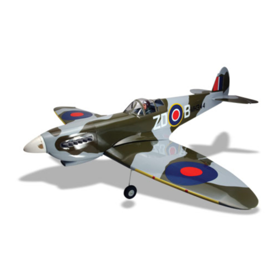
SPECIFICATION
Wingspan :
1,390mm.
Length
: 1,220 mm.
Weight
:
2.4kg.
Parts Listing required (not included).
Glow Engine : 40-46 cu.in. 2 stroke.
52 cu.in.
Instruction Manual book
Electric Motor: AXI 2826/10.
54.75 in.
Battery: 4-5 Cells-Li-Poly-14.8-18.5v- 5.000 mAh - 20 c .
48in.
Speed Control:
5.28lbs.
Propeller :
Recommended R.C: 4 channels with
4 stroke.
60A.
13 x 6.
4-5 servos.
Made in Vietnam.
Advertisement
Table of Contents

Related Manuals for Black Horse Model Spitfire 40


Summary of Contents for Black Horse Model Spitfire 40
- Page 1 Instruction Manual book SPECIFICATION Wingspan : Electric Motor: AXI 2826/10. 1,390mm. 54.75 in. Battery: 4-5 Cells-Li-Poly-14.8-18.5v- 5.000 mAh - 20 c . Length : 1,220 mm.
- Page 2 SPITFIRE 40. This instruction manual is designed to help you build a great flying aeroplane. Please read this manual thoroughly before starting assembly of your SPITFIRE 40. Use the parts listing below to identify all parts. WARNING. Please be aware that this aeroplane is not a toy and if assembled or used incorrectly it is capable of causing injury to people or property.
-
Page 3: Safety Precaution
INSTRUCTION MANUAL. INSTALLING THE AILERON SERVOS. SAFETY PRECAUTION. 1) Install the rubber grommets and brass + This is not a toy eyelets onto the aileron servo. + Be sure that no other flyers are using your radio frequency. + Do not smoke near fuel + Store fuel in a cool, dry place, away from children and pets. - Page 4 SPITFIRE 40. Remove the covering. C/A glue. Top of wing. 4) Using the thread as a guide and using masking tape, tape the servo lead to the end of the thread: carefully pull the thread out. When you have pulled the servo lead out, remove the masking tape and the servo lead from the thread.
- Page 5 INSTRUCTION MANUAL. 1) Using a ruler & pen to draw a straight aileron . 3 Install control horn as same as line as below picture. picture below. 2. Drill through 6mm (diameter) the ai- leron using the control horn as a guide and screw the control horn in place.
-
Page 6: Installing The Aileron Linkages
SPITFIRE 40. 4. Locate one nylon servo arm, and using wire cutters,remove all but one of the arms. Using a 2mm drill bit, enlarge the third hole out from the center of the arm to accommo- date the aileron pushrod wire. - Page 7 INSTRUCTION MANUAL. 3) Using the two landing gear straps as a INSTALLING THE LANDING GREAR. guide, mark the locations of the four 3mm x 12mm mounting screws onto the wing sur- face. 4) Remove the two straps and the gear wire.
-
Page 8: Joining The Wing Halves
SPITFIRE 40. JOINING THE WING HALVES. 1) Location the aluminium wing dihedral brace. Aluminium wing dihedral brace. Masking tape. 2) Test fit the dihedral brace into each wing haft. The brace should slide in easily. Apply masking tape. - Page 9 INSTRUCTION MANUAL. Secure C/A glue. Epoxy glue. Secure Trim...
- Page 10 SPITFIRE 40. Tie wrap...
- Page 11 INSTRUCTION MANUAL. OPTION 2: ENGINE MOUNT. 4 x 25mm Fuel pick- up tube Vent tube Fuel fill tube FUEL TANK. 5. Test fit the stopper assembly into the tank. It may be necessary to remove some of INSTALLING THE STOPPER ASSEMBLY the flashing around the tank opening using ...
- Page 12 SPITFIRE 40. Do not secure the tank into place perma- nently until after balancing the airplane. You may need to remove the tank to mount the battery in the fuel tank compartment Rubber band Mark point Fuel tank. 3 x 20mm.
- Page 13 INSTRUCTION MANUAL. 2) While keeping the back edge of the COWLING. cowl flush with the marks, align the front of 1) Slide the fiberglass cowl over the en- the cowl with the crankshaft of the engine. The gine and line up the back edge of the cowl front of the cowl should be positioned so the with the marks you made on the fuselage.
-
Page 14: Servo Installation
SPITFIRE 40. SERVO INSTALLATION. See picture below. Machine screw. INSTALLING THE SPINNER. Install the spinner backplate, propeller and spinner cone. The spinner cone is held in place using two 3mm x 15mm wood screws. Elevator servo. HORIZONTAL STABILIZER INSTALLA- TION. - Page 15 INSTRUCTION MANUAL. Bottom side. C/A glue. C/A glue. Top side. C/A glue. C/A glue. C/A glue. C/A glue. Top side. C/A glue.
- Page 16 SPITFIRE 40. Centre line. 3) Slide the stabilizer into place in the pre- cut slot in the rear of the fuselage. The stabi- lizer should be pushed firmly against the front of the slot. 4) With the stabilizer held firmly in place, use a pen and draw lines onto the stabilizer where it and the fuselage sides meet.
-
Page 17: Elevator Control Horn Installa- Tion
INSTRUCTION MANUAL. 8) After the epoxy has fully cured, re- Control horn of elevator. move the masking tape or T-pins used to hold the stabilizer in place and carefully inspect the glue joints. Use more epoxy to fill in any gaps that were not filled previously and clean up the excess using a paper towel and rubbing alcohol. -
Page 18: Elevator Pushrod Installation
SPITFIRE 40. Remove covering ELEVATOR PUSHROD INSTALLATION. Elevator pushrod install as same as the way of aileron pushrod. C/A glue. Secure. C/A glue. Elevator servo... -
Page 19: Vertical Stabilizer Installation
INSTRUCTION MANUAL. Cut. Secure. VERTICAL STABILIZER INSTALLATION. Cut. Hinge. C/A glue. - Page 20 SPITFIRE 40. C/A glue. C/A glue. C/A glue. C/A glue. 1) Using a modeling knife, remove the covering from over the precut hinge slot cut into the lower rear portion of the fuselage. This slot accepts the lower rudder hinge.
- Page 21 INSTRUCTION MANUAL. 2) Slide the vertical stabilizer into the slot 4) Remove the vertical. Using a model- in the top of the fuselage. The rear edge of ing knife, remove the covering from below the the stabilizer should be flush with the rear lines you drew.
- Page 22 SPITFIRE 40. mounting area. Apply epoxy to the bottom and CONTROL HORN OF RUDDER top edges of the filler block and to the lower hinge also. Set the stabilizer in place and re- align. Double check all of your measurements once more before the epoxy cures.
-
Page 23: Rudder Pushrod Installation
INSTRUCTION MANUAL. Rudder servo C/A glue. Elevator servo C/A glue. Elevator control horn Elevator pushrod. Bend and cut after Rudder pushrod. Rudder control horn RUDDER PUSHROD INSTALLATION. Rudder pushrod install as same as the way of aileron pushrod. -
Page 24: Installing The Throttle Pushrod
SPITFIRE 40. Elevator pushrod. Throttle pushrod. Cut. Elevator pushrod. Rudder pushrod. INSTALLING THE SWITCH. 1) Cut out the switch hole using a modeling INSTALLING THE THROTTLE PUSHROD. knife. Use a 2mm drill bit and drill out the two mounting holes through the fuselage side. - Page 25 INSTRUCTION MANUAL. Switch INSTALLING THE RECEIVER AND BATTERY. 1. Plug the servo leads and the switch lead into the receiver. You may want to plug an aileron extension into the receiver to make plugging in the aileron servo lead easier when you are installing the wing .
-
Page 26: Mounting The Tail Wheel Bracket
SPITFIRE 40. Receiver. 2. Using a pen, mark the locations of the two mounting screws. Remove the tail wheel bracket and drill 1mm pilot holes at the loca- MOUNTING THE TAIL WHEEL tions marked. BRACKET. -
Page 27: Control Throws
INSTRUCTION MANUAL. *If possible, first attempt to balance the model by changing the position of the receiver bat- tery and receiver. If you are unable to obtain good balance by doing so, then it will be nec- essary to add weight to the nose or tail to achieve proper balance... -
Page 28: Pre-Flight Check
5. Check the receiver antenna . It should be fully extended and not coiled up inside the fuselage. 6. Properly balance the propeller. We wish you many safe and enjoy- able flights with your SPITFIRE 40.
Need help?
Do you have a question about the Spitfire 40 and is the answer not in the manual?
Questions and answers