Advertisement
Table of Contents
- 1 Table of Contents
- 2 Chapter 1 - Overview
- 3 Chapter 2 - System Description
- 4 Chapter 3 - Operating Instructions
- 5 Chapter 4 - Display Calibration
- 6 Chapter 5 - Sender Programming
- 7 Chapter 6 - Installation Guide
- 8 Chapter 7 - Troubleshooting Guide
- 9 Chapter 8 - Specifications
- 10 Chapter 9 - Service and Warranty Information
- 11 Mail in Warranty
- Download this manual
DATE INSTALLED: _____________________________________________________________
SERIAL NUMBER: _____________________________________________________________
CANADA
Garnet Instruments Ltd.
286 Kaska Road
Sherwood Park, AB T8A 4G7
S
L
EE
Holding Tank Monitor
709-N2K NLP / 709-N2KP NLP
MANUAL
IMPORTANT OPERATOR INFORMATION
USA
Garnet US Inc.
5360 Old Granbury Road
Granbury, TX 76049
L II
EVE
garnetinstruments.com
TM
1-800-617-7384
Advertisement
Table of Contents

Related Manuals for Garnet SEELEVEL II


Summary of Contents for Garnet SEELEVEL II
- Page 1 Holding Tank Monitor 709-N2K NLP / 709-N2KP NLP MANUAL IMPORTANT OPERATOR INFORMATION DATE INSTALLED: _____________________________________________________________ SERIAL NUMBER: _____________________________________________________________ CANADA garnetinstruments.com Garnet US Inc. Garnet Instruments Ltd. 5360 Old Granbury Road 286 Kaska Road 1-800-617-7384 Granbury, TX 76049 Sherwood Park, AB T8A 4G7...
-
Page 2: Table Of Contents
GARNET L II Tank Monitor MODEL 709-N2K NLP / 709-N2KP NLP Table of Contents CHAPTER 1 - OVERVIEW .....................3 CHAPTER 2 - SYSTEM DESCRIPTION ..............4 CHAPTER 3 - OPERATING INSTRUCTIONS ............6 CHAPTER 4 - DISPLAY CALIBRATION ..............8 CHAPTER 5 - SENDER PROGRAMMING ............. 12 CHAPTER 6 - INSTALLATION GUIDE .............. -
Page 3: Chapter 1 - Overview
Vehicle industry. The SeeLeveL has a combination of features, accuracy, reliability, and diagnostic capability that have never been available before. Garnet’s 709-N2K series models will monitor the battery voltage, and the fresh water and sewer holding tanks. The information is displayed on a 3-digit alpha-numeric LED display. The 709-N2KP includes a pump switch. -
Page 4: Chapter 2 - System Description
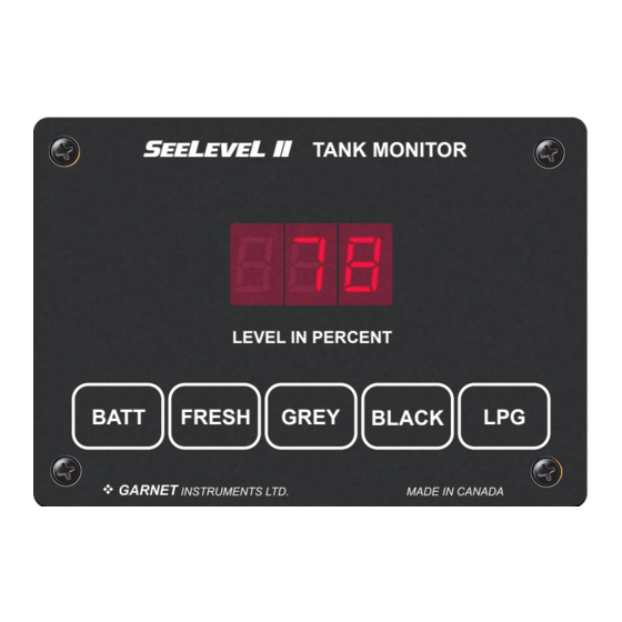
CHAPTER 2 - SYSTEM DESCRIPTION he S consists of a display unit that mounts inside the RV, L II and sender panels that stick to the side of the holding tank. A single 2 conductor wire is used to connect all the sender panels to the display. RV Tank Monitoring System L II 710-SS... - Page 5 How it works 4” (102 mm) L II TANK MONITOR The monitor displays the Monitor depth varies tank level in percent full, on 1” - 1 3/8” (25 - 35 mm) model dependant. a large 3-digit LED display. LEVEL IN PERCENT BATT FRESH GREY...
-
Page 6: Chapter 3 - Operating Instructions
CHAPTER 3 - OPERATING INSTRUCTIONS he display is the only system component that is accessed by the user. All user input to the display is done using the four buttons along the bottom of the display. Operation of the display is as follows: To read a water or sewer tank level: 1. - Page 7 The 709-N2K reports as NMEA device class 75 (sensor communication interface) with an NMEA function code of 150 (fluid level). Garnet Instrument’s manufacturer code is 873, and the 709-N2K product code is 15197. The 709-N2K adheres to NMEA database version 2.200.
-
Page 8: Chapter 4 - Display Calibration
CHAPTER 4 - DISPLAY CALIBRATION Set display to be primary or secondary BATT Press FRESH Press BATT + FRESH at power up = unit mode (primary/secondary) set. Display shows “scn”. Once in that mode, FRESH = primary (“Pri”), GREY = secondary (“SEc”). Press BATT to save and exit. Display firmware revision/visual alarm cue Press (1st),... - Page 9 FRESH Tank Menus Press (1st), (2nd): FRESH BATT Set diagnostic option (no delay) • Diagnostic option displayed for 5 seconds (no hold delay to enter this mode). “diA” displayed. Release either button to enter this mode. After this mode is entered, the sensor’s relative power will be displayed for 5 seconds (“Pxx”...
- Page 10 Edit connected senders (+10 seconds) • Number of senders edit mode is displayed for next 5 seconds. Display shows “FrS”. Release either button to enter the number of senders edit mode. Display will show either “0” (disabled), one or two senders) “SE0”, “SE1”, or “SE2”. Press FRESH to cycle through.
- Page 11 Continuous display mode Press FRESH (1st), FRESH (again, within 5 seconds of first press): Press GREY (1st), GREY (again, within 5 seconds of first press): Press BLACK (1st), BLACK (again, within 5 seconds of first press): • Enables rapid tank read mode. Normal scan of a tank happens approximately every 10 seconds.
-
Page 12: Chapter 5 - Sender Programming
CHAPTER 5 - SENDER PROGRAMMING To program the 710ES or 710SS sender for the correct tank: 1. Since the senders are all connected in parallel to save wiring and to simplify installation, the senders must be programmed so they know which tank they are on. The senders can be programmed for either the fresh, grey, or black tank. - Page 13 2. The senders default to single or bottom operation if the programming is not altered. Consequently, if the sender is for single or bottom operation, nothing further needs to be done to it (beyond programming it for the correct tank). 3.
- Page 14 710ES AND 710SS SENDER PROGRAMMING Page 14 709-N2K NLP/709-N2KP NLP Manual...
- Page 15 710JS SENDER PROGRAMMING 709-N2K NLP/709-N2KP NLP Manual Page 15...
-
Page 16: Chapter 6 - Installation Guide
CHAPTER 6 - INSTALLATION GUIDE 1. Please refer to the “Troubleshooting and Installation Tips” section in Chapter 7 for details on avoiding installation issues. 2. The installation consists of mounting the display inside the RV, cutting and fastening the senders to the sides of the holding tanks, connecting wiring, and programming the display. - Page 17 Tank Sender Options Height Best Resolution Other Acceptable ” - 5” 5” - 7” 7” - 13” 13” - 17” stacked ES 17” - 25” stacked ES stacked SS 25” - 34” stacked SS For single sender applications: The sender ends should be ”...
- Page 18 710ES AND 710SS SENDER Page 18 709-N2K NLP/709-N2KP NLP Manual...
- Page 19 710JS SENDER 709-N2K NLP/709-N2KP NLP Manual Page 19...
- Page 20 7. To make the senders the right length (assuming they are too long) they will need to cut off with a pair of scissors. The end to be cut is the bottom end, which is the opposite end from the top where the wires come out (see the diagrams).
- Page 21 Make sure that the wires from the sender are CAUTION: routed to the RIGHT side of the sender, away from the sender. NEVER route the wires to the left of the sender. If they drape over the sender they could affect the reading. 13.
- Page 22 18. The common alarm output provides a connection to ground when the alarm is active. The maximum current that can be put through the alarm output is 100mA, be sure to use a relay if more current is required. Program and test the alarm output to ensure that it functions as desired.
- Page 23 Typical Double Stacked 710ES or 710SS Sender Installation 709-N2K NLP/709-N2KP NLP Manual Page 23...
-
Page 24: Chapter 7 - Troubleshooting Guide
CHAPTER 7 - TROUBLESHOOTING GUIDE If a sender or its wiring is not operating properly, the following codes are shown on the display: DISPLAY CODE POSSIBLE CAUSE SOLUTION Open circuit 1. If a sender is unresponsive. See “Wiring Diagnostics” O P n 2. - Page 25 The diagnostics can be used to check the wiring and the senders: 1. If a short circuit is showing, disconnect the senders one at a time at the sender location. If the short circuit indication goes away when a sender is removed, then that sender is bad. If all the senders are removed but a short circuit still shows, then the wiring may be shorted.
- Page 26 3. To check the diagnostics, press and hold the button for the tank to be checked, the display will show the level for that tank. 4. While continuing to hold down the button for the tank, press the BATT button. When the display shows ”dIA”, release the buttons, the display will then change to showing the signal power diagnostic.
- Page 27 2. Always ground the senders and the console to the same ground circuit. This is very important; RV’s can have several ground circuits with resistance between them. We have had instances where two consoles are installed with a different ground for the service bay console and interior console.
- Page 28 able to measure on the optimal side. On the drain valve side, the best choice is to elevate the sender to avoid reading a puddle at the drain valve. 4. The close proximity of metal to the sender can be misinterpreted as water, since they have similar electrical characteristics.
- Page 29 the soaking hopefully the build-up will be flushed away when the tank is drained and flushed. If you still have symptoms the treatment may required a few more times. The waste did not build up on the tank wall in one day, so it may not dissolve in one treatment! The build-up looks like water to the system since it holds a significant volume of water in the build-up area.
- Page 30 2. When fastening the display to the panel, make sure that it is centered in the hole and not resting on one edge. 3. Non-conductive mounting spacers are available to help prevent damaging the display. Contact Garnet for further details. Page 30 709-N2K NLP/709-N2KP NLP Manual...
- Page 31 How to avoid damaging the display or pump switch due to excessive current: 1. Please be aware that the water pump switch circuit has a limitation on current draw of 7.5 amps, some large pumps can draw over 10 amps. These high drain pumps must use a relay or the display console printed circuit will overheat and damage the display permanently.
-
Page 32: Chapter 8 - Specifications
CHAPTER 8 - SPECIFICATIONS Resolution JS sender: ¼" (6 mm) ES sender: ⅜" (10 mm) SS sender: ½" (13 mm) +/- 8% or better, limited by resolution and tank height Accuracy: and shape. +32 °F to +140 °F (0 °C to + 60 °C) Temperature range: Sender materials: 0.008"... -
Page 33: Chapter 9 - Service And Warranty Information
Alberta, T8A 4G7. Returned warranted items will be repaired or replaced at the discretion of Garnet Instruments. Any Garnet items under the Garnet Warranty Policy that are deemed irreparable by Garnet Instruments will be replaced at no charge or a credit will be issued for that item subject to the customer’s request. - Page 34 Page 34 709-N2K NLP/709-N2KP NLP Manual...
-
Page 35: Mail In Warranty
MAIL IN WARRANTY... - Page 36 Printed in Canada CANADA Garnet Instruments Ltd. Garnet US Inc. www.garnetinstruments.com 286 Kaska Road 5360 Old Granbury Road Sherwood Park, AB T8A 4G7 Granbury, TX 76049 1-800-617-7384...
Need help?
Do you have a question about the SEELEVEL II and is the answer not in the manual?
Questions and answers