Table of Contents
Advertisement
Quick Links
S
IMPORTANT OPERATOR INFORMATION
DATE INSTALLED: _______________________________________________________________________________
DATE INSTALLED: ____________________________________________________________________
UNIT NUMBER: _________________________________________________________________________________
TANK NUMBER: _____________________________________________________________________
COMPARTMENT: _______________________________________________________________________________
MINIMUM TANK READOUT: ________________________________________________________
DISPLAY CALIBRATION UNITS (e.g. inches, gallons): ___________________________________________
MAXIMUM TANK READOUT: ________________________________________________________
MINIMUM TANK READOUT: ___________________________________________________________________
MAXIMUM TANK READOUT: ___________________________________________________________________
ALARM POINT (IF APPLICABLE): ________________________________________________________________
SPILLSTOP EMPTY POINT (IF APPLICABLE): ____________________________________________________
ALARM 1
SPILLSTOP HORN POINT (IF APPLICABLE): _____________________________________________________
ALARM 2
SPILLSTOP SHUTDOWN POINT (IF APPLICABLE): ______________________________________________
ALARM 3
AUTOMATIC ALARM:
ALARM 4
Printed in Canada
www.garnetinstruments.com
900D6D Manual
L
EE
EVE
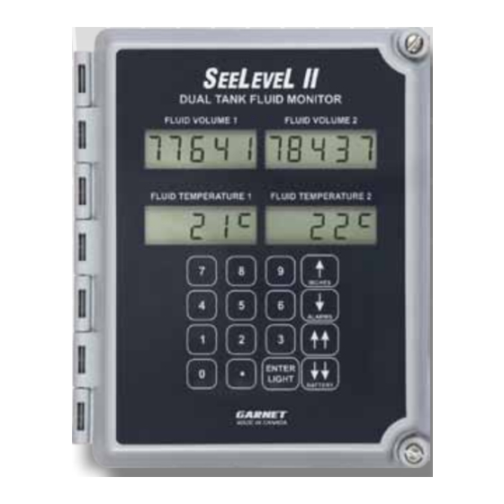
Tank Fluid Monitor
MODEL 900D6 DUAL
MANUAL
IMPORTANT OPERATOR INFORMATION
ALARM
HIGH VOLUME
WARNING LEVEL: ____________________________________________________
EMPTY LEVEL: ________________________________________________________
L II
ALARM
LOW VOLUME
TM
Normally Open or
Normally Closed
□
□
NO
NC
□
□
NO
NC
□
□
NO
NC
□
□
NO
NC
Page 1
Advertisement
Table of Contents

Related Manuals for Garnet 900D6 DUAL


Summary of Contents for Garnet 900D6 DUAL
- Page 1 L II Tank Fluid Monitor MODEL 900D6 DUAL MANUAL IMPORTANT OPERATOR INFORMATION IMPORTANT OPERATOR INFORMATION DATE INSTALLED: _______________________________________________________________________________ DATE INSTALLED: ____________________________________________________________________ UNIT NUMBER: _________________________________________________________________________________ TANK NUMBER: _____________________________________________________________________ COMPARTMENT: _______________________________________________________________________________ MINIMUM TANK READOUT: ________________________________________________________ DISPLAY CALIBRATION UNITS (e.g. inches, gallons): ___________________________________________...
-
Page 2: Table Of Contents
CHAPTER 4 - INSTALLATION GUIDE ..............18 CHAPTER 5 - TROUBLESHOOTING GUIDE ............19 CHAPTER 6 - SERVICE & WARRANTY INFORMATION ........21 CHAPTER 7 - SPECIFICATIONS ................22 CHAPTER 8 - MASTER CODE ................... 23 900D6 Dual Manual_v2.2 9-May-2017 Page 2 900D6D Manual... -
Page 3: Chapter 1 - Overview
CHAPTER 1 - OVERVIEW ongratulations on purchasing the Garnet Instruments Model 900D6 S L II Fluid Monitor for Tanks. The SeeLeveL II represents the latest in state of the art liquid monitoring equipment for stationary tank applications. The S L II is... -
Page 4: Chapter 2 - System Description
CHAPTER 2 - SYSTEM DESCRIPTION he SeeLeveL II consists of a sender bar, a donut shaped float, a fiber optic interconnect cable, and a display. The sender bar is mounted vertically in the tank with the float sliding up and down around it in accordance with the fluid level. - Page 5 IMPORTANT NOTICE: SENDER BAR LIMITS OF RESISTIVITY The temperature of the product in the tank should be limited to approximately +90°C (+194°F). Damage to the float and sender bar can occur if this value is exceeded. The float and tube used in the manufacturing of the sender bar It should be noted that certain corrosive is polyethylene.
- Page 6 Even though the gauge has 1/4” resolution, it is only necessary to program the volume for each whole inch; the display calculates the volume at the 1/4”, 1/2”, and 3/4” points. Programming is a two step process, first the chart of volume for the inches of level is entered, and then the offset has to be set to account for variations in tank height and sender mounting position.
- Page 7 Display Batteries: A set of four alkaline ‘D’ cells in the display enclosure powers all gauge display functions. This allows for total stand alone operation of the gauge. The battery pack should last from 3 to 4 years, depending on usage of the LCD backlight. A display with the optional 901D6 cellular or 904D6 satellite communications board use 8 ‘D’...
-
Page 8: Chapter 3 - Keypad Operating Instructions
CHAPTER 3 - KEYPAD OPERATING INSTRUCTIONS he keypad consists of the 16 buttons on the front of the display, and is used for the following functions: 1. To show inches, temperature, alarm status, and battery condition as described in the previous chapter. 2. - Page 9 Since the operation of the gauge can be severely compromised by improper keypad use, there are security features incorporated into the gauge. These security features also allow the owner of the tank to better manage rentals and billing by controlling access to the gauge functions.
- Page 10 own Master code and the Master code is available upon request from the installer/service provider. The master code can be used to configure the installed 900D6 optional boards, turn 904 satellite option uploads on and off, view 904 satellite options diagnostic information, and set the 901 cellular option’s TCP address destination and port.
- Page 11 active. Press ↑ UP to select degrees Fahrenheit or ↓ DOWN to select degrees Celsius. 6. Press ENTER to store the new temperature format , “StOrE” will be shown momentarily. 7. GAUGE ID MENUS: Press ↑↑ FAST UP to access the Tank id menus, the display will show “GAUGE IdEnt”...
-
Page 12: Serial Communications
14. If a menu is left without pressing ENTER, any change to that menu item will NOT be stored. If no button is pressed for 3 minutes then the gauge will exit programming mode and any changes which have not been stored will be ignored. To access the Long User Code (LUC) menu (alarm point &... - Page 13 6. To access other alarm menus, press ↑↑ FAST UP or ↓↓ FAST DOWN. If an alarm menu is left without pressing ENTER, any change to that menu item will NOT be stored. 7. SERIAL ACTIVATION MENU: Press ↓↓ FAST DOWN until “SErIAL On”...
- Page 14 4. Press the number buttons to enter the new six digit code, the existing code will disappear from the appropriate display and the new value will be shown. Press ENTER to save the new code. If exactly six digits are not entered, then “Error Error” is shown momentarily and the previous code reappears.
- Page 15 a complete calibration table; the gauge can calculate the table from a single value. 12. Determine the volume corresponding to one inch of level, for example if the tank was a 400 barrel, 20 foot tank, this would be 400 bbls / (20 ft * 12 in/ft)” = 1.66666666--- barrels per inch.
- Page 16 will go to the table calibration menus to allow viewing of the calculated calibration tables for the two tanks. 17. CALIBRATION TABLE MENU: If the tank does not have straight vertical sides (such as a round tank on its side), the volume per inch of depth is not constant throughout the tank.
- Page 17 27. PORT MENU: To access the menu, press ↑↑ FAST UP or ↓↓ FAST DOWN until the displays show “Port 7778”. This should only need to be changed under Garnet’s request. This is only shown if configured with 901 cellular option.
-
Page 18: Chapter 4 - Installation Guide
CHAPTER 4 - INSTALLATION GUIDE Since installation details can vary widely with application, contact Garnet Instruments Ltd. for additional installation details. WARNING: All wires and/or cables used for installation must be rated for temperatures between -40°F to +167°F (-40°C to +75°C). - Page 19 The wiring colors for the following 903 Modbus options are not included because there is not a standardized system for specific wire colors. When installing the 903 Modbus option using RS232, please use the following diagram. (no special operating conditions) 903 Wiring Guide 903 Modbus RS232 Connector...
- Page 20 When installing the 905 WITS option, please use the following diagram. (no special operating conditions) 905 Wiring Guide 905 WITS Wire Color WITS Connector RS422 RX POS/485 POS Yellow RS422 RX NEG/485 NEG White/Yellow RS422 TX POS/RS232 TX Blue RS422 TX NEG/RS232 RX White/Blue RS422/485/232 GROUND Black...
-
Page 21: Chapter 5 - Troubleshooting Guide
CHAPTER 5 - TROUBLESHOOTING GUIDE here are only 5 serviceable components in the system: the float, the sender bar, the interconnecting fiber optic cable, the display, and the batteries. If the float is sunk, the display will read the bottom tank reading all the time. -
Page 22: Chapter 6 - Service & Warranty Information
Garnet or an Authorized Dealer. The warranty period will start from the date of purchase or installation as indicated on the warranty card. Under these warranties, Garnet shall be responsible only for actual loss or damage suffered and then only to the extent of Garnet’s invoiced price of the product. - Page 23 • Replace the fuse (if installed), provided this is done in a non-hazardous area, and is done with a Bussmann/Eaton AGC-2. Any additional maintenance or service must be done by qualified Garnet peronnel or under the advisement of qualified Garnet peronnel. Not following these guidelines may result in the warranty being voided.
-
Page 24: Chapter 7 - Specifications
CHAPTER 7 - SPECIFICATIONS Sender materials: Sender bar is polyethylene or 316 SS. Sender temp. Number of senders is the sender bar length divided sensors: by the sender spacing of 16”. Sender battery: 3.6 volt lithium battery module, 5 year expected lifetime. - Page 25 Resolution: 1/4 inch (6 mm) Accuracy: +/- 1/8 inch (3 mm) Display temp. range: -40°F to +140°F (-40°C to + 60°C) Product temp. range: -40°F to +194°F (-40°C to + 90°C) Display temp. drift: Alarm temp. drift: Current Rating Display Boards Continuous Peak Opto Backlight...
-
Page 26: Chapter 8 - Master Code
CHAPTER 8 - MASTER CODE The Master code is available upon request. Note: This code should not be revealed to anyone who does not need to know. Page 26 900D6D Manual...
Need help?
Do you have a question about the 900D6 DUAL and is the answer not in the manual?
Questions and answers