Table of Contents
Advertisement
S
DATE INSTALLED: ____________________________________________________________________
SERIAL NUMBER: ____________________________________________________________________
Black Water Tank
Grey Water Tank
Fresh Water Tank
CANADA
Garnet Instruments
286 Kaska Road
Sherwood Park, AB T8A 4G7
L
EE
EVE
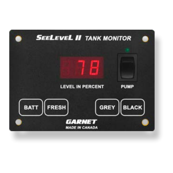
RV Tank Monitor
MODEL 709-P3
MANUAL
IMPORTANT OPERATOR INFORMATION
Signal Level
USA
Garnet US Inc.
5360 Old Granbury Road
Granbury, TX 76049
L II
TM
Sender Height
RVgauge.com
|
1-800-617-7384
Advertisement
Table of Contents

Related Manuals for Garnet SEELEVEL II 709-P3


Summary of Contents for Garnet SEELEVEL II 709-P3
- Page 1 DATE INSTALLED: ____________________________________________________________________ SERIAL NUMBER: ____________________________________________________________________ Signal Level Sender Height Black Water Tank Grey Water Tank Fresh Water Tank CANADA RVgauge.com 1-800-617-7384 Garnet Instruments Garnet US Inc. 286 Kaska Road 5360 Old Granbury Road Sherwood Park, AB T8A 4G7 Granbury, TX 76049...
-
Page 2: Table Of Contents
GARNET L II Tank Monitor MODEL 709-P3 Table of Contents CHAPTER 1 - OVERVIEW .....................3 CHAPTER 2 - SYSTEM DESCRIPTION ..............4 CHAPTER 3 - OPERATING INSTRUCTIONS ............6 CHAPTER 4 - DISPLAY CALIBRATION ..............7 CHAPTER 5 - SENDER PROGRAMMING ...............9 CHAPTER 6 - INSTALLATION GUIDE ..............13 CHAPTER 7 - TROUBLESHOOTING GUIDE ............ -
Page 3: Chapter 1 - Overview
CHAPTER 1 - OVERVIEW he S Tank Monitor represents a massive leap L II forward in level measurement technology for the Recreational Vehicle industry. The S L™ has a combination of features, accuracy, reliability, and diagnostic capability that have never been available before. -
Page 4: Chapter 2 - System Description
CHAPTER 2 - SYSTEM DESCRIPTION he SeeLeveL consists of a display unit that mounts inside the RV, and sender panels that stick to the side of the holding tank. A single 2 conductor wire is used to connect all the sender panels to the display. - Page 5 If a sender is operating properly and connected to the display with good wiring, then the display will show the level normally. If the wiring is disconnected, shorted, or cut, or if the sender panel is defective, then the display will indicate an error code. The various error codes are shown in the troubleshooting chapter.
-
Page 6: Chapter 3 - Operating Instructions
CHAPTER 3 - OPERATING INSTRUCTIONS he display is the only system component that is accessed by the user. All user input to the display is done using the four buttons along the bottom of the display. Operation of the display is as follows: To read a water or sewer tank level: 1. -
Page 7: Chapter 4 - Display Calibration
CHAPTER 4 - DISPLAY CALIBRATION To program the LED brightness: 1. If the display is to be used inside the coach, the LED brightness should be low. If it is to be used in the service bay area where sunlight can reach it, the LED brightness should be high. 2. - Page 8 4. When the programming mode is entered, the display will show “FrS” if entering the number of senders for the fresh tank, “GrS” if entering the grey tank, or “bLS” if entering the black tank. When this occurs release both buttons. 5.
-
Page 9: Chapter 5 - Sender Programming
CHAPTER 5 - SENDER PROGRAMMING To program the 710ES or 710SS sender for the correct tank: 1. Since the senders are all connected in parallel to save wiring and to simplify installation, the senders must be programmed so they know which tank they are on. The senders can be programmed for either the fresh, grey, or black tank. - Page 10 2. The senders default to single or bottom operation if the programming is not altered. Consequently, if the sender is for single or bottom operation, nothing further needs to be done to it (beyond programming it for the correct tank). 3.
- Page 11 710ES AND 710SS SENDER PROGRAMMING 709-P3 Manual Page 11...
- Page 12 710JS SENDER PROGRAMMING Page 12 709-P3 Manual...
-
Page 13: Chapter 6 - Installation Guide
CHAPTER 6 - INSTALLATION GUIDE 1. Please refer to the “Troubleshooting and Installation Tips” section in Chapter 7 for details on avoiding installation issues. 2. The installation consists of mounting the display inside the RV, cutting and fastening the senders to the sides of the holding tanks, connecting wiring, and programming the display. - Page 14 Tank Sender Options Height Best Resolution Other Acceptable ” - 5” 5” - 7” 7” - 13” 13” - 17” stacked ES 17” - 25” stacked ES stacked SS 25” - 34” stacked SS For single sender applications: The sender ends should be ”...
- Page 15 710ES AND 710SS SENDER 709-P3 Manual Page 15...
- Page 16 710JS SENDER Page 16 709-P3 Manual...
- Page 17 7. To make the senders the right length (assuming they are too long) they will need to cut off with a pair of scissors. The end to be cut is the bottom end, which is the opposite end from CAUTION: DO NOT cut the sides, and DO NOT cut the 710ES sender shorter than 4 ”.
- Page 18 Make sure that the wires from the sender CAUTION: are routed to the RIGHT side of the sender, away from the sender. NEVER route the wires to the left of the sender. If they drape over the sender they could affect the reading. Secure the wires with tie wraps or something similar so that the wires do not rattle or press against the sender, this may result in sender damage or wires breaking over time.
- Page 19 Typical Double Stacked 710ES or 710SS Sender Installation 709-P3 Manual Page 19...
-
Page 20: Chapter 7 - Troubleshooting Guide
CHAPTER 7 - TROUBLESHOOTING GUIDE If a sender or its wiring is not operating properly, the following codes are shown on the display: DISPLAY CODE POSSIBLE CAUSE SOLUTION Open circuit 1. If a sender is unresponsive. See “Wiring Diagnostics” O P n 2. - Page 21 The diagnostics can be used to check the wiring and the senders: 1. If a short circuit is showing, disconnect the senders one at a time at the sender location. If the short circuit indication goes away when a sender is removed, then that sender is bad. If all the senders are removed but a short circuit still shows, then the wiring may be shorted.
- Page 22 3. To check the diagnostics, press and hold the button for the tank to be checked, the display will show the level for that tank. 4. While continuing to hold down the button for the tank, press the BATT button. When the display shows ”dIA”, release the buttons, the display will then change to showing the signal power diagnostic.
- Page 23 too close to entrance boxes for shore power or bundled with other high AC voltage lines or junction boxes. 2. Always ground the senders and the console to the same ground circuit. This is very important; RV’s can have several ground circuits with resistance between them.
- Page 24 On sloped tanks, which are used to promote complete draining, one alternative is to measure the end of the tank opposite from the drain valve. It may be necessary to extend the wire harness to be able to measure on the optimal side. On the drain valve side, the best choice is to elevate the sender to avoid reading a puddle at the drain valve.
- Page 25 trip, leave with a high concentration of the chemical in the tank and approximately 30% full of fresh water. Hopefully you can drive for 2-3 days allowing the tank levels to rise through normal use. We recommend that you exceed the level that you see the system report when the tank is empty.
- Page 26 adhesive from working properly; use a heat gun to warm the tank surface if necessary. Also be sure the surface is dry, again a heat gun is the best way to dry the bonding area. Finally, the surface of the tank must be smooth. The adhesive works much better on smooth surfaces, if necessary use an orbital sander with fine grit paper (220 grit) to quickly accomplish the desired smoothness.
- Page 27 2. When fastening the display to the panel, make sure that it is centered in the hole and not resting on one edge. 3. Non-conductive mounting spacers are available to help prevent damaging the display. Contact Garnet for further details. How to avoid damaging the display or pump switch due to excessive current: 1.
-
Page 28: Chapter 8 - Specifications
CHAPTER 8 - SPECIFICATIONS Resolution JS sender: ¼" (6 mm) ES sender: ⅜" (10 mm) SS sender: ½" (13 mm) +/- 8% or better, limited by resolution and tank height Accuracy: and shape. +32 to +140 °F (0 to + 60 °C) Temperature range: Sender materials: 0.008"... -
Page 29: Chapter 9 - Service And Warranty Information
Alberta, T8A 4G7. Returned warranted items will be repaired or replaced at the discretion of Garnet Instruments. Any Garnet items under the Garnet Warranty Policy that are deemed irreparable by Garnet Instruments will be replaced at no charge or a credit will be issued for that item subject to the customer’s request.
Need help?
Do you have a question about the SEELEVEL II 709-P3 and is the answer not in the manual?
Questions and answers