Table of Contents
Advertisement
Advertisement
Table of Contents

Related Manuals for Garnet SEELEVEL II 714


Summary of Contents for Garnet SEELEVEL II 714
- Page 1 L II Tank Monitor 714-P MANUAL IMPORTANT OPERATOR INFORMATION DATE INSTALLED: _____________________________________________________________ Signal Level Sender Height Black Water Tank Grey Water Tank Fresh Water Tank Printed in Canada INSTRUMENTS LTD. INSTRUMENTS LTD.
-
Page 2: Table Of Contents
GARNET L II Tank Monitor MODEL 714 / 714-PH Table of Contents CHAPTER 1 - OVERVIEW .....................3 CHAPTER 2 - SYSTEM DESCRIPTION ..............4 CHAPTER 3 - OPERATING INSTRUCTIONS ............5 CHAPTER 4 - DISPLAY CALIBRATION ..............6 CHAPTER 5 - SENDER PROGRAMMING ...............9 CHAPTER 6 - INSTALLATION GUIDE .............. -
Page 3: Chapter 1 - Overview
CHAPTER 1 - OVERVIEW he S Tank Monitor represents a massive leap L II forward in level measurement technology for the Recreational Vehicle industry. The S L has a combination of features, accuracy, reliability, and diagnostic capability that have never been available before. -
Page 4: Chapter 2 - System Description
CHAPTER 2 - SYSTEM DESCRIPTION he S L consists of a display unit that mounts inside the RV, and sender panels that stick to the side of the holding tank. A single two conductor wire is used to connect all the sender panels to the display. -
Page 5: Chapter 3 - Operating Instructions
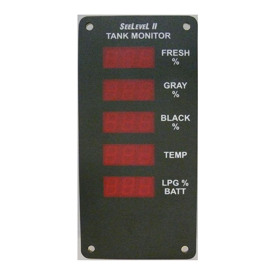
CHAPTER 3 - OPERATING INSTRUCTIONS he display is the only system component that is accessed by the user. Operation of the display is as follows: To read a tank level: The levels in percent are continuously shown on the LED displays, and are updated every 10 seconds. -
Page 6: Chapter 4 - Display Calibration
CHAPTER 4 - DISPLAY CALIBRATION To display code revision number and display primary/ secondary status, and for setting display options: 1. Press and hold the bottom button and then the top button. 2. The display will show “COd rEL 3.11 Pri/SEC Scn”. This shows the code release as 3.10 and whether the display is set as primary or secondary. - Page 7 3. Press the top “TOP” button to toggle between primary and secondary scanning mode. The bottom button will store and exit the menu, all the displays will show “Sto” until the button is released. Normal operation will then start. 4. The LPG must be wired to the primary display only. 5.
- Page 8 To calibrate the LPG sender: 1. The LPG tank must be full when the sender is calibrated, otherwise the calibration will be invalid. Fill the LPG tank by using an alternate measurement method, such as weight, a spit valve, or a mechanical gauge on the tank. 2.
-
Page 9: Chapter 5 - Sender Programming
CHAPTER 5 - SENDER PROGRAMMING To program the sender for the correct tank: 1. Since the senders are all connected in parallel to save wiring and to simplify installation, the senders must be programmed so they know which tank they are on. The senders can be programmed for either the fresh, grey, or black tank. - Page 10 2. The senders default to single or bottom operation if the programming is not altered. Consequently, if the sender is for single or bottom operation, nothing further needs to be done to it (beyond programming it for the correct tank). 3.
- Page 11 714 / 714-P Manual Page 11...
-
Page 12: Chapter 6 - Installation Guide
CHAPTER 6 - INSTALLATION GUIDE (NEW OEM INSTALLATIONS ONLY) 1. The installation consists of mounting the display inside the RV, cutting and fastening the senders to the sides of the holding tanks, connecting wiring, and programming the display. 2. Mount the display by cutting a hole in the wall 2 1/4” wide by 4 3/4”... - Page 13 senders are calibrated to account for this distance from the bottom of the tank. The sender is cut to the nearest even 1.5 inch in length, for example, a system with a tank height of 11.75 inches, cut the sender to be 10.5 inches long, this allows 5/8”...
- Page 14 Page 14 714 / 714-P Manual...
- Page 15 9. The senders need to be programmed so they know which tank they are on. This is done by selectively cutting off the tabs on the top of the sender. See the chapter entitled “SENDER PROGRAMMING” and the section “To program the sender for the correct tank”...
- Page 16 chapter entitled “TROUBLESHOOTING GUIDE” and the section “To review the sender diagnostics” for details). If the signal power is too low, make sure that the sender(s) is well stuck to the side of the tank and that the tank is reasonably clean inside, as a large buildup will reduce signal strength.
- Page 17 Typical Dual Stacked Sender Installation 714 / 714-P Manual Page 17...
-
Page 18: Chapter 7 - Troubleshooting Guide
CHAPTER 7 - TROUBLESHOOTING GUIDE Display trouble codes: If a sender or its wiring is not operating properly, the following codes are shown on the display: 1. If a sender is unresponsive or there is an open circuit in the wiring so that the sender is not connected, the display will indicate an open circuit by showing “OPn”... - Page 19 tanks, which increases sender accuracy at low tank levels. If this memory should fail, “CAL” will be flashed on the LED display, indicating a calibration failure. It will be necessary to replace the display if this occurs. The diagnostics can be used to check the wiring and the senders: 1.
- Page 20 b. The sender height is the number of receive segments present in the sender. To determine the length of the sender, multiply the calibration by 1.5 to get the length in inches. The senders always auto calibrate to the length that they are cut, so this diagnostic allows the user to confirm the length and to make sure that the auto calibration is working properly.
-
Page 21: Chapter 8 - Service And Warranty Information
Garnet or an Authorized Dealer. The warranty period will start from the date of purchase or installation as indicated on the warranty card. Under these warranties, Garnet shall be responsible only for actual loss or damage suffered and then only to the extent of Garnet’s invoiced price of the product. -
Page 22: Chapter 9 - Specifications
CHAPTER 9 - SPECIFICATIONS Resolution: 3/8 inch (10 mm) Accuracy: +/- 8% or better, limited by resolution and tank height and shape Temperature range: +32 to +140°F (0 to + 60°C) Sender materials: 0.008” thick glass epoxy circuit board with conformal coating circuit... - Page 23 NOTES:...
Need help?
Do you have a question about the SEELEVEL II 714 and is the answer not in the manual?
Questions and answers