Table of Contents
Advertisement
Quick Links
DATE INSTALLED: _____________________________________________________________
SERIAL NUMBER: _____________________________________________________________
Black Water Tank
Grey Water Tank
Fresh Water Tank
CANADA
Garnet Instruments
286 Kaska Road
Sherwood Park, AB T8A 4G7
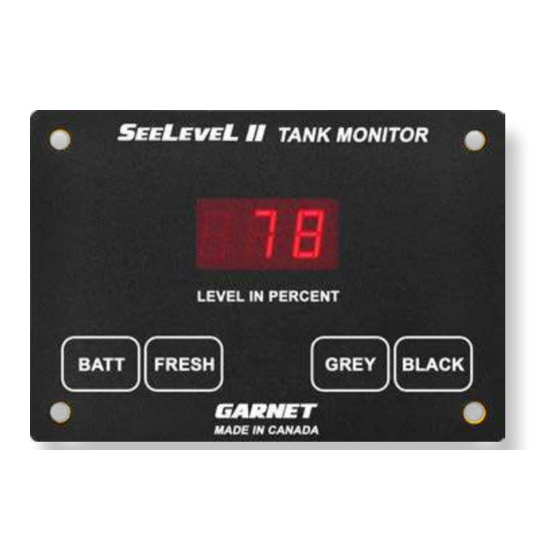
RV Tank Monitor
MODEL 709-RVC NLP
MANUAL
IMPORTANT OPERATOR INFORMATION
Signal Level
USA
Garnet US Inc.
5360 Old Granbury Road
Granbury, TX 76049
Sender Height
Advertisement
Table of Contents

Related Manuals for Garnet 709-RVC NLP


Summary of Contents for Garnet 709-RVC NLP
- Page 1 RV Tank Monitor MODEL 709-RVC NLP MANUAL IMPORTANT OPERATOR INFORMATION DATE INSTALLED: _____________________________________________________________ SERIAL NUMBER: _____________________________________________________________ Signal Level Sender Height Black Water Tank Grey Water Tank Fresh Water Tank CANADA Garnet Instruments Garnet US Inc. 286 Kaska Road 5360 Old Granbury Road...
-
Page 2: Table Of Contents
NOTE: expands on information for any procedures. CAUTION: explains safety information that could cause damage to the product, including data loss. WARNING: explains dangers that might result in personal injury or death. 709-RVC NLP Manual_v7.1 - 23-Sep-2022 Page 2 709-RVC NLP Manual... -
Page 3: Chapter 1 - Overview
Model 709-RVC NLP will monitor the battery voltage and the fresh water and sewer holding tanks. The 709-RVC NLP is also RV-C network compatible, the tank levels and alarms are available on the RV-C bus for the fresh, grey and black tanks. -
Page 4: Chapter 2 - System Description
5 minutes before shutting off. This allows the user to monitor the filling or draining of a tank. By pressing two buttons at once, the diagnostic functions can be accessed; these are described in detail in the troubleshooting chapter. Page 4 709-RVC NLP Manual... - Page 5 Another example is the alarm could be used on the black tank to prevent toilet use when the tank is full. 709-RVC NLP Manual Page 5...
-
Page 6: Chapter 3 - Operating Instructions
BATT button, the display will immediately switch to showing the value for the new button. The 5 second timeout is restarted every time a button is pressed. 4. There is no hold mode for the battery voltage. Page 6 709-RVC NLP Manual... - Page 7 4. Some displays have a wired connection as shown in the red box in the image below. If this is what your display has, connect the wiring according to the following table. Wire colour Function Black Ground Blue CAN Low (-) White CAN High (+) 709-RVC NLP Manual Page 7...
-
Page 8: Chapter 4 - Display Calibration
3. While continuing to hold down the button for the tank, press and hold the BATT button. The display will immediately show ”dIA” (diagnostics), continue to hold down both buttons until the display enters the programming mode, this should take about 10 seconds. Page 8 709-RVC NLP Manual... - Page 9 6. To set the alarm point, press and hold the same tank button, after about 3 more seconds, the display will show “FAS”, “GAS”, or “bAS”, depending on which tank is selected. Release the button. 709-RVC NLP Manual Page 9...
- Page 10 3. The FRESH button sets the mode to PRIMARY, the GREY button to SECONDARY and the BATT button saves and exits. NOTE: The battery voltage is calibrated at the factory; this should never need to be changed. Page 10 709-RVC NLP Manual...
- Page 11 5 seconds until the display shows a number such as “4.10”, the first number is the hardware version and the last two numbers are the software version. When viewing is complete, release both buttons to return to normal operation. 709-RVC NLP Manual Page 11...
-
Page 12: Chapter 5 - Sender Programming
This is done with the tab at the top center of the sender. See the following diagram. Page 12 709-RVC NLP Manual... - Page 13 6. If the “GRY” or “BLK” tab has been removed by mistake, the sender can be changed to a fresh tank sender by cutting the other corner tab (“BLK” or “GRY”). 7. Refer to the 710JS sender programming diagram. 709-RVC NLP Manual Page 13...
- Page 14 710ES AND 710SS SENDER PROGRAMMING Page 14 709-RVC NLP Manual...
- Page 15 710JS SENDER PROGRAMMING 709-RVC NLP Manual Page 15...
-
Page 16: Chapter 6 - Installation Guide
6. Measure the height of the tank to determine which sender CAUTION: DO NOT mix sender types when stacking senders. Page 16 709-RVC NLP Manual... - Page 17 2” (SS sender) . The top and bottom senders should be approximately the same length for best results. For example, if the tank height is 22”, then 22”- ”- ”- ”= 21 ”, so the total length 709-RVC NLP Manual Page 17...
- Page 18 710ES AND 710SS SENDER Page 18 709-RVC NLP Manual...
- Page 19 710JS SENDER 709-RVC NLP Manual Page 19...
- Page 20 11. Do steps 5 to 10 for the other two holding tanks. 12. Connect all the blue wires from the senders together, and to the blue wire from the display. Connect the black wire from Page 20 709-RVC NLP Manual...
- Page 21 7.5 amps. The use of a relay is required if more than 7.5 amps is needed. A 7.5 amp (max) fuse must be installed in the series with the 12V power circuit to the switch! 709-RVC NLP Manual Page 21...
- Page 22 The maximum current that can be put through the alarm output is 100mA, be sure to use a relay if more current is required. Program and test the alarm output to ensure that it functions as desired. Page 22 709-RVC NLP Manual...
- Page 23 Typical Double Stacked 710ES or 710SS Sender Installation 709-RVC NLP Manual Page 23...
-
Page 24: Chapter 7 - Troubleshooting Guide
The only LPG diagnostic code is the open circuit. If the wiring to the LPG sender is shorted then the LPG will always show “O”. LEVEL IN PERCENT NOTE: There are no diagnostics for battery voltage. Page 24 709-RVC NLP Manual... - Page 25 If this memory should fail, “CAL” will be flashed on the LED display, indicating a calibration failure. It will be necessary to replace the display if this occurs. 7. There are no diagnostics for the battery voltage. 709-RVC NLP Manual Page 25...
- Page 26 The senders always auto calibrate to the length that they are cut, so this diagnostic allows the user to confirm the length and to make sure that the auto calibration is working properly. Page 26 709-RVC NLP Manual...
- Page 27 What to do if operation becomes erratic or stops completely: 1. Make sure all wiring connections are solid. Do not use spade connectors to join wiring as they will degrade over time. Use insulated crimp-on butt connectors or solder and insulate the wire connections. 709-RVC NLP Manual Page 27...
- Page 28 & top; depending on the tank wall thickness the inside height is ½” to 1” shorter than the outside height. Knowing the wall thickness of your tank will allow you to find the optimal sender position; placing the sender where it can Page 28 709-RVC NLP Manual...
- Page 29 This way you should see ‘0’ before the pump starts to suck air. Some tanks have a sump style draw system, in this case there is no concern with unusable water, just allow 709-RVC NLP Manual Page 29...
- Page 30 100%. The top of the sender must be at least ¼” to ½” away from the top of the tank to allow for wall thickness. Page 30 709-RVC NLP Manual...
- Page 31 7.5 amps. A relay is required if more than 7.5 amps is needed for the pump. 709-RVC NLP Manual Page 31...
- Page 32 2. When fastening the display to the panel, make sure that it is centered in the hole and not resting on one edge. 3. Non-conductive mounting spacers are available to help prevent damaging the display. Contact Garnet for further details. How to avoid damaging the display or pump switch due to excessive current: 1.
-
Page 33: Chapter 8 - Specifications
12 V power and ground required for display. LPG: Pump switch: Maximum voltage: 16 volts DC Common Alarm Output: Maximum current: 100 mA DC Polarity: The output makes a connection to ground when the alarm is on. 709-RVC NLP Manual Page 33... -
Page 34: Chapter 9 - Service And Warranty Information
Alberta, T8A 4G7. Returned warranted items will be repaired or replaced at the discretion of Garnet Instruments. Any Garnet items under the Garnet Warranty Policy that are deemed irreparable by Garnet Instruments will be replaced at no charge or a credit will be issued for that item subject to the customer’s request.
Need help?
Do you have a question about the 709-RVC NLP and is the answer not in the manual?
Questions and answers