
Related Manuals for Dell E30S Series


Summary of Contents for Dell E30S Series
- Page 1 Dell EMC PowerEdge T430 Owner's Manual Regulatory Model: E30S Series Regulatory Type: E30S001 February 2021 Rev. A07...
- Page 2 A WARNING indicates a potential for property damage, personal injury, or death. © 2017 - 2021 Dell Inc. or its subsidiaries. All rights reserved. Dell, EMC, and other trademarks are trademarks of Dell Inc. or its subsidiaries. Other trademarks may be trademarks of their respective owners.
-
Page 3: Table Of Contents
Contents Chapter 1: Dell PowerEdge T430 system overview................. 8 Supported configurations on PowerEdge T430 systems..................9 Front panel ..................................10 Front panel features of 16 x 2.5-inch hot swappable hard drive chassis............10 Front panel features of a 8 x 3.5-inch hot swappable hard drive chassis............. 12 Front panel features of 8 x 3.5-inch hot swappable hard drive chassis in rack mode........14... - Page 4 System Setup..................................41 Viewing System Setup............................... 42 System Setup details..............................42 System BIOS.................................42 iDRAC Settings utility..............................66 Device Settings................................67 Dell Lifecycle Controller..............................67 Embedded systems management..........................67 Boot Manager..................................67 Viewing Boot Manager...............................68 Boot Manager main menu............................68 PXE boot..................................... 69 Chapter 7: Installing and removing system components...............70...
- Page 5 Installing the optical drive or tape drive.........................82 Cooling shroud................................... 84 Removing the cooling shroud........................... 84 Installing the cooling shroud............................. 85 Hot-swappable hard drives.............................86 Removing a hot swappable hard drive carrier...................... 86 Installing a hot swappable hard drive carrier......................87 Removing a hard-drive blank............................ 88 Installing a hard-drive blank............................
- Page 6 Removing the iDRAC port card..........................130 Installing the iDRAC port card..........................131 Replacing an SD vFlash card...........................132 Internal dual SD module (optional)..........................132 Removing the internal dual SD module ........................133 Installing the internal dual SD module ........................133 Internal SD card................................134 Removing an (optional) internal SD card......................
- Page 7 Chapter 8: Using system diagnostics..................174 Dell Embedded System Diagnostics..........................174 Running the Embedded System Diagnostics from Boot Manager..............174 Running the Embedded System Diagnostics from the Dell Lifecycle Controller........174 System diagnostics controls........................... 175 Chapter 9: Jumpers and connectors ..................176 System board connectors..............................176...
-
Page 8: Chapter 1: Dell Poweredge T430 System Overview
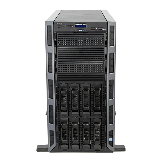
Dell PowerEdge T430 system overview The Dell PowerEdge T430 is a rackable tower server that supports up to two processors based on the Intel Xeon E5-2600 v3 or v4 processor family, up to 12 DIMMs, and storage capacity of up to 16 hard drives/SSDs. -
Page 9: Supported Configurations On Poweredge T430 Systems
Supported configurations on PowerEdge T430 systems Figure 1. System view with supported configurations Dell PowerEdge T430 system overview... -
Page 10: Front Panel
2. NMI button 3. System identification button 4. LCD menu buttons 5. Information tag 6. LCD panel 7. USB management port/iDRAC Direct port 8. USB port 9. Optical drive or tape-drive bay 10. Physical drives Dell PowerEdge T430 system overview... - Page 11 The iDRAC Direct port is micro USB 2.0-compliant. This port port enables you to access the iDRAC Direct features. For more information, see the Integrated Dell Remote Access Controller User's Guide at www.dell.com/poweredgemanuals. USB port The USB ports are 9-pin and 3.0-compliant. These ports enable you to connect USB devices to the system.
-
Page 12: Front Panel Features Of A 8 X 3.5-Inch Hot Swappable Hard Drive Chassis
2. NMI button 3. System identification button 4. LCD menu buttons 5. Information tag 6. LCD panel 7. USB management port/iDRAC Direct port 8. USB port 9. Optical drive or tape-drive bay 10. Physical drives Dell PowerEdge T430 system overview... - Page 13 The iDRAC Direct port is micro USB 2.0-compliant. This port port enables you to access the iDRAC Direct features. For more information, see the Integrated Dell Remote Access Controller User's Guide at www.dell.com/poweredgemanuals. USB port The USB ports are 9-pin and 3.0-compliant. These ports enable you to connect USB devices to the system.
-
Page 14: Front Panel Features Of 8 X 3.5-Inch Hot Swappable Hard Drive Chassis In Rack Mode
System identification button To reset the iDRAC (if not disabled on the iDRAC setup NOTE: page by pressing F2 during system boot), press and hold the System ID button for more than 15 seconds. Dell PowerEdge T430 system overview... - Page 15 The iDRAC Direct port is micro USB 2.0-compliant. This port port enables you to access the iDRAC Direct features. For more information, see the Integrated Dell Remote Access Controller User's Guide at www.dell.com/poweredgemanuals. Video connector Enables you to connect a display device to the system. For more information, see the Technical specifications section.
-
Page 16: Front Panel Features Of 4 X 3.5-Inch Cabled Hard Drive Chassis
Figure 5. Front panel features and indicators- 4 x 3.5 inch cabled hard-drive chassis 1. Power button 2. NMI button 3. System identification button 4. Information tag 5. Diagnostic indicators 6. USB ports 7. Optical drive or tape-drive bay Dell PowerEdge T430 system overview... -
Page 17: Lcd Panel
The LCD panel of your system provides system information, status, and error messages to indicate if the system is functioning correctly or if the system needs attention. For more information about error messages, see the Dell Event and Error Messages Reference Guide at Dell.com/openmanagemanuals >OpenManage software. - Page 18 LCD message with an SEL entry. Select Simple to view LCD error messages in a simplified user-friendly description. For more information about error messages, see the Dell Event and Error Messages Reference Guide at Dell.com/ openmanagemanuals > OpenManage software.
-
Page 19: Back Panel Features
NIC ports, and USB and VGA ports. A majority of the expansion card ports can be accessed from the back panel. The hot swappable and cabled power supply units are accessible from the back panel. Dell PowerEdge T430 system overview... -
Page 20: Back Panel Features
13. PCIe expansion card slots (6) Table 7. Back panel Features Indicator, button, Icon Description or connector Power supplies Up to two 495 W, 750 W, or 1100 W redundant AC power Redundant power (PSU1 and PSU2) supplies. supply Dell PowerEdge T430 system overview... -
Page 21: Diagnostic Indicators
Check the System Event Log or system messages for the specific issue. For more information ● When the system is turned on. about error messages, see the Dell Event and ● When the system is in standby. Error Messages Reference Guide at Dell.com/ ●... -
Page 22: Hot Swappable Hard Drive Indicator Codes
The activity LED indicates whether hard drive is currently in use or not. The status LED indicates the power condition of the hard drive. Figure 8. Hot swappable hard drive indicators 1. hard drive activity indicator 2. hard drive status indicator Dell PowerEdge T430 system overview... -
Page 23: Nic Indicator Codes
(1 Gbps or 10 Gbps). Link indicator is amber The NIC is connected to a valid network at less than its maximum port speed. Activity indicator is flashing. green Network data is being sent or received. Dell PowerEdge T430 system overview... -
Page 24: Redundant Power Supply Unit Indicator Codes
Do not disconnect the power cord or unplug the PSU when updating firmware. If firmware update is interrupted, the PSUs will not function. You must roll back the PSU firmware by using Dell Lifecycle Controller. See Dell Lifecycle Controller User’s Guide at Dell.com/ idracmanuals. -
Page 25: Indicator Codes For Non-Redundant Power Supply Unit
When the Redundancy option is set to Mirror Mode in the Integrated Devices screen of System Setup, the NOTE: information is replicated from one SD card to another. ● Single card operation — single card operation is supported, but without redundancy. Dell PowerEdge T430 system overview... -
Page 26: Locating Service Tag Of Your System
Tag are found on the front of the system by pulling out the information tag. Alternatively, the information may be on a sticker on the chassis of the system. This information is used by Dell to route support calls to the appropriate personnel. -
Page 27: Chapter 2: Converting The System From Tower Mode To Rack Mode
Damage due to servicing that is not authorized by Dell is not covered by your warranty. Read and follow the safety instructions that came with the product. - Page 28 (2) iii. front panel Next steps 1. Install the system cover. 2. Install the system in a rack. For more information, see the system’s Rack Installation Guide at Dell.com/ poweredgemanuals. Converting the system from tower mode to rack mode...
-
Page 29: Chapter 3: Documentation Resources
This section provides information about the documentation resources for your system. To view the document that is listed in the documentation resources table: ● From the Dell EMC support site: 1. Click the documentation link that is provided in the Location column in the table. - Page 30 Methods to download firmware and drivers section in this document. Managing your system For information about systems management https://www.dell.com/poweredgemanuals software offered by Dell, see the Dell OpenManage Systems Management Overview Guide. For information about setting up, using, and www.dell.com/openmanagemanuals >...
-
Page 31: Chapter 4: Technical Specifications
Processor specifications • PSU specifications • System battery specifications • Expansion bus specifications • Memory specifications • Drive specifications • Ports and connectors specifications • Environmental specifications Chassis dimensions Figure 14. Chassis dimensions of Dell PowerEdge T430 system Technical specifications... -
Page 32: Chassis Weight
Table 15. Dimensions of Dell PowerEdge T430 system System 304.5 mm 218 mm 471.3 mm 430.3 mm 443.3 mm 594.82 mm 578.42 mm 542.2 mm PowerEdge (11.99 (8.58 (18.55 (16.94 (17.45 (23.42 (22.77 (21.35 T430 inches) inches) inches) inches) inches) -
Page 33: Memory Specifications
Table 18. Supported PCI express generation 3 expansion cards (continued) PCIe Slot Processor Connection Height Length Link Width Slot Width 3 (Gen3) Processor 1 Full height Full length 4 (Gen3) Processor 1 Full height Full length 5 (Gen3) Processor 2 Full height Half length 6 (Gen3) -
Page 34: Tape Drive
Table 21. Optical Drive Specifications Drives Optical drive One optional SATA DVD-ROM drive or DVD+/-RW drive. If your system is installed with a double-width GPU NOTE: card, the system supports only one 5.25 inch removable media storage device. Tape drive The PowerEdge T430 system supports up to two optional 5.25 inch tape drive. -
Page 35: Nic Ports
8, 16, 32 1280 x 1024 8, 16, 32 1440 x 900 8, 16, 32 Environmental specifications For additional information about environmental measurements for specific system configurations, see Dell.com/ NOTE: environmental_datasheets. Table 24. Environmental specifications Type Condition Temperature or Specification... -
Page 36: Particulate And Gaseous Contamination Specifications
Table 24. Environmental specifications (continued) Type Condition Temperature or Specification Operating 0.26 G at 5 Hz to 350 Hz (all operation orientations). Storage 1.88 G at 10 Hz to 500 Hz for 15 minutes (all six sides tested). Maximum Shock Operating Six consecutively executed shock pulses in the positive and negative x, y, and z axes of 40 G for up to 2.3 ms. -
Page 37: Expanded Operating Temperature
● Nonredundant power supplies are not supported. ● Cabled power supply units are not supported. ● Non-Dell qualified peripheral cards and/or peripheral cards greater than 25 W are not supported. When operating in the expanded temperature range, system performance may be impacted. -
Page 38: Chapter 5: Initial System Setup And Configuration
The Integrated Dell Remote Access Controller (iDRAC) is designed to make system administrators more productive and improve the overall availability of Dell EMC systems. iDRAC alerts administrators to system issues, helps them perform remote system management, and reduces the need for physical access to the system. -
Page 39: Options To Install The Operating System
You must have iDRAC credentials to log in to iDRAC. NOTE: For more information about logging in to iDRAC and iDRAC licenses, see the latest Integrated Dell Remote Access Controller User's Guide at Dell.com/idracmanuals. Options to install the operating system... -
Page 40: Downloading The Drivers And Firmware
Downloading the drivers and firmware Dell EMC recommends that you download and install the latest BIOS, drivers, and systems management firmware on your system. Prerequisites Ensure that you clear the web browser cache before downloading the drivers and firmware. Steps 1. -
Page 41: Chapter 6: Pre-Operating System Management Applications
Options to manage the pre-operating system applications Your system has the following options to manage the pre-operating system applications: ● System Setup ● Boot Manager ● Dell Lifecycle Controller ● Preboot Execution Environment (PXE) Related concepts System Setup on page 41... -
Page 42: Viewing System Setup
The iDRAC settings utility is an interface to set up and configure the iDRAC parameters by using UEFI (Unified Extensible Firmware Interface). You can enable or disable various iDRAC parameters by using the iDRAC settings utility. For more information about this utility, see Integrated Dell Remote Access Controller User’s Guide at Dell.com/idracmanuals. - Page 43 System Information on page 52 Memory Settings on page 53 Processor Settings on page 55 SATA Settings on page 57 Integrated Devices on page 60 Serial Communication on page 61 System Profile Settings on page 63 Miscellaneous Settings on page 65 iDRAC Settings utility on page 66 Device Settings...
- Page 44 Option Description Specifies options to change the processor power management settings, memory frequency, and so on. System Profile Settings Specifies options to configure the system security settings, such as system password, setup password, System Security Trusted Platform Module (TPM) security. It also manages the power and NMI buttons on the system. Specifies options to change the system date, time, and so on.
- Page 45 Boot Settings details About this task The Boot Settings screen details are explained as follows: Option Description Enables you to set the boot mode of the system. Boot Mode CAUTION: Switching the boot mode may prevent the system from booting if the operating system is not installed in the same boot mode.
- Page 46 ● For the latest information about supported operating systems, go to Dell.com/ossupport. Related references Boot Settings on page 44 Related tasks Boot Settings details on page 45 Viewing Boot Settings on page 44 Changing the boot order About this task You may have to change the boot order if you want to boot from a USB key or an optical drive.
- Page 47 2. Press F2 immediately after you see the following message: F2 = System Setup If your operating system begins to load before you press F2, wait for the system to finish booting, and then NOTE: restart your system and try again. 3.
- Page 48 If your operating system begins to load before you press F2, wait for the system to finish booting, and then NOTE: restart your system and try again. 3. On the System Setup Main Menu screen, click System BIOS. 4. On the System BIOS screen, click Network Settings. 5.
- Page 49 System Security Settings details About this task The System Security Settings screen details are explained as follows: Option Description Improves the speed of applications by performing encryption and decryption by using the Advanced Intel AES-NI Encryption Standard Instruction Set (AES-NI). This option is set to Enabled by default. Sets the system password.
- Page 50 Secure Boot Custom Policy Settings Secure Boot Custom Policy Settings is displayed only when Secure Boot Policy is set to Custom. Viewing Secure Boot Custom Policy Settings To view the Secure Boot Custom Policy Settings screen, perform the following steps: Steps 1.
- Page 51 5. Reenter the system password, and click OK. 6. In the Setup Password field, type your setup password and press Enter or Tab. A message prompts you to reenter the setup password. 7. Reenter the setup password, and click OK. 8.
- Page 52 Operating with a setup password enabled If Setup Password is set to Enabled, type the correct setup password before modifying the system setup options. If you do not type the correct password in three attempts, the system displays the following message: Invalid Password! Number of unsuccessful password attempts: <x>...
- Page 53 System Information details About this task The System Information screen details are explained as follows: Option Description Specifies the system model name. System Model Name Specifies the BIOS version installed on the system. System BIOS Version Specifies the current version of the Management Engine firmware. System Management Engine Version...
- Page 54 Specifies the memory operating mode. The options available are Optimizer Mode, Advanced ECC Memory Mode, Mirror Mode, Spare Mode, Spare with Advanced ECC Mode, Dell Fault Resilient Mode and Operating Mode Dell NUMA Fault Resilient Mode. This option is set to Optimizer Mode by default.
- Page 55 Processor Settings You can use the Processor Settings screen to view the processor settings, and perform specific functions such as enabling virtualization technology, hardware prefetcher, and logical processor idling. Related references Processor Settings details on page 55 System BIOS on page 42 Related tasks Viewing Processor Settings on page 55...
- Page 56 Enables or disables the X2Apic mode. X2Apic Mode Controls the turbo engagement. Enable this option only when System Profile is set to Performance. Dell Controlled Turbo Depending on the number of installed CPUs, there may be up to four processor listings.
- Page 57 SATA Settings You can use the SATA Settings screen to view the SATA settings of SATA devices and enable RAID on your system. Related references System BIOS on page 42 Related tasks SATA Settings details on page 57 Viewing SATA Settings on page 57 Viewing SATA Settings To view the SATA Settings screen, perform the following steps:...
- Page 58 Option Description Option Description Specifies the total capacity of the hard drive. This field is undefined for removable Capacity media devices such as optical drives. Sets the drive type of the selected device. For Embedded SATA settings in ATA mode, set this field to Port B Auto to enable BIOS support.
- Page 59 Option Description Option Description Specifies the type of drive attached to the SATA port. Drive Type Specifies the total capacity of the hard drive. This field is undefined for removable Capacity media devices such as optical drives. Sets the drive type of the selected device. For Embedded SATA settings in ATA mode, set this field to Port G Auto to enable BIOS support.
- Page 60 Integrated Devices You can use the Integrated Devices screen to view and configure the settings of all integrated devices including the video controller, integrated RAID controller, and the USB ports. Related references System BIOS on page 42 Related tasks Integrated Devices details on page 60 Viewing Integrated Devices on page 60...
- Page 61 Option Description Enables or disables the integrated network card. Integrated Network Card 1 The Embedded NIC1 and NIC2 options are only available on systems that do not have Embedded NIC1 NOTE: and NIC2 Integrated Network Card 1. Enables or disables the Embedded NIC1 and NIC2 options. If set to Disabled, the NIC may still be available for shared network access by the embedded management controller.
- Page 62 Viewing Serial Communication To view the Serial Communication screen, perform the following steps: Steps 1. Turn on, or restart your system. 2. Press F2 immediately after you see the following message: F2 = System Setup If your operating system begins to load before you press F2, wait for the system to finish booting, and then NOTE: restart your system and try again.
- Page 63 Option Description Sets the remote console terminal type. This option is set to VT 100/VT 220 by default. Remote Terminal Type Enables or disables the BIOS console redirection when the operating system is loaded. This option is set Redirection After to Enabled by default.
- Page 64 You can only change the rest of the options if the mode is set to Custom. This option is set to Performance Per Watt Optimized (DAPC) by default. DAPC is Dell Active Power Controller.
- Page 65 Related tasks Viewing System Profile Settings on page 63 Miscellaneous Settings You can use the Miscellaneous Settings screen to perform specific functions such as updating the asset tag and changing the system date and time. Related references System BIOS on page 42 Related tasks Miscellaneous Settings details on page 65...
-
Page 66: Idrac Settings Utility
Accessing some of the features on the iDRAC settings utility needs the iDRAC Enterprise License upgrade. NOTE: For more information about using iDRAC, see Dell Integrated Dell Remote Access Controller User's Guide at Dell.com/ idracmanuals. -
Page 67: Device Settings
Dell Lifecycle Controller Dell Lifecycle Controller (LC) provides advanced embedded system management capabilities including system deployment, configuration, update, maintenance, and diagnosis. LC is delivered as part of the iDRAC out-of-band solution and Dell EMC system embedded Unified Extensible Firmware Interface (UEFI) applications. -
Page 68: Viewing Boot Manager
Menu Enables you to access System Setup. Launch System Setup Exits the Boot Manager and invokes the Dell Lifecycle Controller program. Launch Lifecycle Controller Enables you to launch System Utilities menu such as System Diagnostics and UEFI shell. System Utilities... -
Page 69: Pxe Boot
● Launch Diagnostics ● BIOS/UEFI Update File Explorer ● Reboot System Depending on the boot mode selected, you might have BIOS or UEFI Update File Explorer. NOTE: Related references Boot Manager on page 67 PXE boot You can use the Preboot Execution Environment (PXE) option to boot and configure the networked systems, remotely. To access the PXE boot option, boot the system and then press F12. -
Page 70: Chapter 7: Installing And Removing System Components
Damage due to servicing that is not authorized by Dell is not covered by your warranty. Read and follow the safety instructions that are shipped with your product. -
Page 71: Before Working Inside Your System
2. Disconnect the system from the electrical outlet and disconnect the peripherals. 3. If installed, remove the front bezel. 4. If applicable, remove the system from the rack. For more information, see the Rack Installation placemat at Dell.com/poweredgemanuals. 5. Lay the system on its side. 6. Remove the system cover. -
Page 72: Front Bezel (Optional)
Front bezel (optional) The front bezel is attached to the front side of the system and prevents accidents while removing the hard drive or when pressing the reset or power button. The front bezel can also be locked for additional security. Removing the optional front bezel Steps 1. -
Page 73: System Feet
2. Insert the bezel tabs into the bezel tab slots in the chassis. 3. Press the release latch, and push the bezel toward the system until the bezel locks into place. 4. Lock the bezel by using the key. Figure 16. Installing the front bezel a. -
Page 74: Installing The System Feet
Figure 17. Removing the system feet 1. slot (12) 2. screw hole (4) 3. tab (12) 4. base of the tower 5. system feet (4) 6. screw (4) Next steps Installing the system feet. Installing the system feet Prerequisites CAUTION: Installing the feet on a stand-alone tower system is necessary to provide a stable foundation for the system. -
Page 75: Caster Wheels - Optional
Figure 18. Installing the system feet 1. slot (12) 2. screw hole (4) 3. tab (12) 4. base of the tower 5. system feet (4) 6. screw (4) Next steps Place the system upright on a flat and stable surface, and turn the system feet outward. Caster wheels –... -
Page 76: Removing Caster Wheels
Figure 19. Installing caster wheels 1. support unit 2. screw for support unit (2) 3. slot on base of the tower (4) 4. wheel assembly unit (2) 5. screw for wheel assembly (2) Removing caster wheels Prerequisites 1. Follow the safety guidelines listed in the Safety instructions section. 2. -
Page 77: System Cover
Figure 20. Removing caster wheels 1. slot on base of the tower (4) 2. wheel assembly unit (2) 3. screw for wheel assembly (2) 4. screw for support unit (2) 5. support unit System cover The system cover protects the components inside the system and helps in maintaining air flow inside the system. Removing the system cover activates the intrusion switch. -
Page 78: Installing The System Cover
2. Press the cover release latch and remove the system cover. Figure 21. Removing the system cover 1. system 2. system cover 3. cover release latch 4. cover release latch lock Next steps 1. Install the system cover. 2. Place the system upright on its feet on a flat and stable surface. 3. -
Page 79: Inside The System
Damage due to servicing that is not authorized by Dell is not covered by your warranty. Read and follow the safety instructions that are shipped with your product. -
Page 80: Optical Drives And Tape Drives (Optional)
If your system is installed with a double-width GPU card, the system supports only one 5.25 inch removal media NOTE: storage. You can also install a Dell PowerVault RD1000 removable media device on your system. NOTE: For systems with hot-swappable hard drives, the optical and tape drives can be configured as follows:... -
Page 81: Removing The Optical Drive Or Tape Drive
Damage due to servicing that is not authorized by Dell is not covered by your warranty. Read and follow the safety instructions that are shipped with your product. -
Page 82: Installing The Optical Drive Or Tape Drive
Damage due to servicing that is not authorized by Dell is not covered by your warranty. Read and follow the safety instructions that are shipped with your product. - Page 83 The system board connectors are ODD1/TBU and ODD2/TBU. The system can connect up to two optical drives, or one optical drive with one SATA tape backup unit, and one SAS tape backup unit using Dell OpenManage IT Assistant. Figure 26. Installing the optical drive or tape drive a.
-
Page 84: Cooling Shroud
Damage due to servicing that is not authorized by Dell is not covered by your warranty. Read and follow the safety instructions that are shipped with your product. -
Page 85: Installing The Cooling Shroud
Damage due to servicing that is not authorized by Dell is not covered by your warranty. Read and follow the safety instructions that are shipped with your product. -
Page 86: Hot-Swappable Hard Drives
For more information on these hard drives, see the 512e and 4Kn Disk Formats whitepaper and 4K Sector HDD FAQ document at dell.com/poweredgemanuals. Choosing the right drive type depends on the usage pattern. Improper use of Entry Hard Drives (workload rating exceed 55TB/ year) will lead to significant risk and increase the drives failure rate. -
Page 87: Installing A Hot Swappable Hard Drive Carrier
Figure 29. Removing a hot swappable hard drive or SSD a. release button b. hard drive carrier c. hard drive carrier handle Next steps 1. If you are not replacing the hard drive immediately, insert a hard drive carrier blank in the empty hard drive slot, or install a hard drive carrier. -
Page 88: Removing A Hard-Drive Blank
Damage due to servicing that is not authorized by Dell is not covered by your warranty. Read and follow the safety instructions that came with the product. -
Page 89: Installing A Hard-Drive Blank
Figure 31. Removing a 2.5 inch hard-drive blank a. hard-drive blank b. release button Figure 32. Removing a 3.5 inch hard-drive blank a. hard-drive blank b. release button Installing a hard-drive blank Prerequisites 1. Follow the safety guidelines listed in the Safety instructions section. 2. -
Page 90: Removing A 2.5-Inch Hot Swappable Hard Drive From A 3.5-Inch Hard Drive Adapter
Damage due to servicing that is not authorized by Dell is not covered by your warranty. Read and follow the safety instructions that came with the product. -
Page 91: Installing A 2.5-Inch Hot Swappable Hard Drive Into A 3.5-Inch Hard Drive Adapter
Damage due to servicing that is not authorized by Dell is not covered by your warranty. Read and follow the safety instructions that are shipped with your product. -
Page 92: Removing A 3.5-Inch Hard Drive Adapter From A 3.5-Inch Hot Swappable Hard Drive Carrier
Damage due to servicing that is not authorized by Dell is not covered by your warranty. Read and follow the safety instructions that are shipped with your product. -
Page 93: Removing A Hot Swappable Hard Drive From A Hard Drive Carrier
Damage due to servicing that is not authorized by Dell is not covered by your warranty. Read and follow the safety instructions that are shipped with your product. -
Page 94: Installing A Hot Swappable Hard Drive Into A Hard Drive Carrier
Damage due to servicing that is not authorized by Dell is not covered by your warranty. Read and follow the safety instructions that are shipped with your product. -
Page 95: Installing The Internal Hard Drive Bay
Damage due to servicing that is not authorized by Dell is not covered by your warranty. Read and follow the safety instructions that are shipped with your product. -
Page 96: Removing A Cabled Drive
Steps 1. Align the internal hard-drive bay with the tabs on the chassis and slide the internal hard drive bay into the chassis. 2. Secure the internal hard drive bay to the chassis using the two captive screws. Next steps 1. - Page 97 Figure 43. Cabling—Cabled hard-drives 1. SATA optical drive connector on system board 2. SATA tape drive connector on system board 3. SATA A connector on system board 4. system board 5. hard drives 6. tape drive 7. optical drive Installing and removing system components...
-
Page 98: Installing A Cabled Hard Drive
Damage due to servicing that is not authorized by Dell is not covered by your warranty. Read and follow the safety instructions that are shipped with your product. - Page 99 1. Follow the safety guidelines listed in the Safety instructions section. 2. Keep the #2 Phillips screwdriver ready. 3. Follow the procedure listed in the Before working inside your system section. 4. Disconnect the power and data cables from the hard drive(s) in the internal hard drive bay. 5.
-
Page 100: Hard Drive Backplane
Damage due to servicing that is not authorized by Dell is not covered by your warranty. Read and follow the safety instructions that are shipped with your product. - Page 101 Figure 47. Removing an x16 hard drive backplane 1. x16 hard drive backplane 2. release pin 3. power connector 4. power cable 5. signal cable 6. SAS cable Figure 48. Connectors on an x16 hard drive backplane 1. backplane power connector 2.
- Page 102 Figure 49. Cabling—x16 hard drive backplane with two PERC cards 1. SATA optical drive connector on system board 2. SATA tape drive connector on system board 3. PERC card 4. SAS connector on PERC card 5. SAS connector on PERC card 6.
- Page 103 Figure 50. Cabling—x8 hard drive backplane with one PERC card 1. SATA optical drive connector on system board 2. SATA tape drive connector on system board 3. SATA B connector on system board 4. SATA A connector on system board 5.
-
Page 104: Installing The Hard Drive Backplane
Damage due to servicing that is not authorized by Dell is not covered by your warranty. Read and follow the safety instructions that are shipped with your product. -
Page 105: Four-Slot Hard Drive Blank
2. Slide down the hard drive backplane until the release pin locks into the slot. 3. Connect the SAS, power, and signal cables to the hard drive backplane. Figure 52. Installing an x16 hard drive backplane 1. x16 hard drive backplane 2. -
Page 106: Installing A Four-Slot Hard Drive Blank
Steps 1. Using a screwdriver, push the release tabs on the corners of the blank from inside the system, to unlock the four-slot hard drive blank from the chassis. 2. From the front of the system, pull the four-slot hard drive blank at the corners until it is free of the hard drive slot. Figure 53. -
Page 107: System Memory
Figure 54. Installing the four-slot hard drive blank a. four-slot hard drive blank b. release tab (4) Next steps 1. Follow the procedure listed in the After working inside your system section. System memory Your system supports DDR4 registered DIMMs (RDIMMs). It supports DDR4 voltage specifications. MT/s indicates DIMM speed in MegaTransfers per second. -
Page 108: General Memory Module Installation Guidelines
Figure 55. Memory socket locations Memory channels are organized as follows: Table 30. Memory channels Processor Channel 0 Channel 1 Channel 2 Channel 3 Processor 1 slots A1 and A5 slots A2 and A6 slots A3 and A7 slots A4 and A8 Processor 2 slot B1 slot B2... -
Page 109: Mode-Specific Guidelines
● Populate all sockets with white release tabs first, and then black. ● Populate the sockets by highest capacity DIMM in the following order - first in sockets with white release levers and then black. For example, if you want to mix 16 GB and 8 GB DIMMs, populate 16 GB DIMMs in the sockets with white release tabs and 8 GB DIMMs in the sockets with black release tabs. -
Page 110: Sample Memory Configurations
Memory mirroring Memory mirroring offers the strongest memory module reliability mode compared to all other modes, providing improved uncorrectable multi-bit failure protection. In a mirrored configuration, the total available system memory is one half of the total installed physical memory. Half of the installed memory is used to mirror the active memory modules. In the event of an uncorrectable error, the system switches over to the mirrored copy. - Page 111 Table 34. Memory configurations—single processor (continued) System DIMM Size Number of DIMM Rank, DIMM Slot Population Capacity (in (in GB) DIMMs Organization, and Frequency 1R, x8, 2400 MT/s, A1, A2, A3, A4, A5, A6 1R, x8, 2133 MT/s, 1R, x8, 1866 MT/s 1R, x8, 2400 MT/s, A1, A2, A3 1R, x8, 2133 MT/s,...
- Page 112 Table 34. Memory configurations—single processor (continued) System DIMM Size Number of DIMM Rank, DIMM Slot Population Capacity (in (in GB) DIMMs Organization, and Frequency A1, A2, A3 2R, x8, 2400 MT/s, 2R, x4, 2133 MT/s, 2R, x4, 1866 MT/s 2R, x8, 2400 MT/s, A1, A2, A3, A4, A5, A6, A7, A8 2R, x4, 2133 MT/s, 2R, x4, 1866 MT/s,...
- Page 113 Table 35. Memory configurations—two processors (continued) System DIMM Size Number of DIMM Rank, DIMM Slot Population Capacity (in GB) DIMMs Organization, and (in GB) Frequency 2R, x8, 1866 MT/s A1, B1 2R, x8, 2400 MT/s, 2R, x8, 2133 MT/s, 2R, x8, 1866 MT/s A1, A2, A3, A4, A5, A6, A7, A8, 2R, x8, 2400 MT/s, B1, B2, B3, B4...
-
Page 114: Removing Memory Modules
Damage due to servicing that is not authorized by Dell is not covered by your warranty. Read and follow the safety instructions that are shipped with your product. -
Page 115: Installing Memory Modules
Damage due to servicing that is not authorized by Dell is not covered by your warranty. Read and follow the safety instructions that are shipped with your product. -
Page 116: Cooling Fans
● An internal cooling fan ● An optional external cooling fan at the back of the chassis When selecting or upgrading your system configuration, verify the system power consumption with the Dell Energy NOTE: Smart Solution Advisor at Dell.com/ESSA to ensure optimum power utilization. -
Page 117: Removing The Internal Cooling Fan
Damage due to servicing that is not authorized by Dell is not covered by your warranty. Read and follow the safety instructions that are shipped with your product. -
Page 118: Removing The External Cooling Fan
Removing the external cooling fan Prerequisites 1. Follow the safety guidelines listed in Safety instructions. 2. Follow the procedure listed in Before working inside your system. 3. Remove the cooling shroud. Steps 1. Disconnect the external cooling fan power cable from the system board. 2. -
Page 119: Installing The External Cooling Fan
Installing the external cooling fan Prerequisites 1. Follow the safety guidelines listed in Safety instructions. 2. Follow the procedure listed in Before working inside your system. Steps 1. Route the external cooling fan power cable into the system through the slot at the back of the chassis. 2. -
Page 120: Internal Usb Memory Key (Optional)
Damage due to servicing that is not authorized by Dell is not covered by your warranty. Read and follow the safety instructions that are shipped with your product. -
Page 121: Expansion Card Holder
Figure 61. Installing the internal USB memory key a. USB memory key b. USB port Next steps 1. Follow the procedure listed in the After working inside your system section. 2. While booting, press F2 to enter System Setup and verify that the USB memory key is detected by the system. Expansion card holder Removing the expansion card holder Prerequisites... -
Page 122: Installing The Expansion Card Holder
Figure 62. Removing the expansion card holder a. projection (2) b. tab c. expansion card holder Installing the expansion card holder Prerequisites 1. Follow the safety guidelines listed in Safety instructions. 2. Follow the procedure listed in Before working inside your system. -
Page 123: Expansion Cards
Figure 63. Installing the expansion card holder a. projection (2) b. tab c. expansion card holder Next steps 1. Follow the procedure listed in After working inside your system on page 71. Expansion cards An expansion card in the system is an add-on card that can be inserted into an expansion slot on the system board or riser card to add enhanced functionality to the system through the expansion bus. -
Page 124: Gpu Card Installation Guidelines
Damage due to servicing that is not authorized by Dell is not covered by your warranty. Read and follow the safety instructions that are shipped with your product. - Page 125 3. Hold the expansion card by its edge, pull the card up to remove it from the expansion card slot and out of the system. 4. Install the filler bracket by performing the following steps: a. Align the tab on the filler bracket with the expansion card slot. b.
-
Page 126: Installing An Expansion Card
Damage due to servicing that is not authorized by Dell is not covered by your warranty. Read and follow the safety instructions that are shipped with your product. -
Page 127: Removing A Gpu Card
Damage due to servicing that is not authorized by Dell is not covered by your warranty. Read and follow the safety instructions that are shipped with your product. -
Page 128: Installing An Optional Gpu Card
Damage due to servicing that is not authorized by Dell is not covered by your warranty. Read and follow the safety instructions that are shipped with your product. -
Page 129: Idrac Port Card (Optional)
An SD vFlash card is a Secure Digital (SD) card that plugs into the SD vFlash card slot in the iDRAC port card. It provides persistent on-demand local storage and a custom deployment environment that enables automation of server configuration, scripts, and imaging. It emulates a USB device. For more information, see the Integrated Dell Remote Access Controller User's Guide at Dell.com/idracmanuals. -
Page 130: Removing The Idrac Port Card
Damage due to servicing that is not authorized by Dell is not covered by your warranty. Read and follow the safety instructions that are shipped with your product. -
Page 131: Installing The Idrac Port Card
Damage due to servicing that is not authorized by Dell is not covered by your warranty. Read and follow the safety instructions that are shipped with your product. -
Page 132: Replacing An Sd Vflash Card
Replacing an SD vFlash card Prerequisites This procedure applies only to the eight hard drive system. NOTE: Steps 1. Locate the vFlash media slot on the system. 2. To remove the installed SD vFlash card, push inward on the card to release it and pull the card from the card slot. Figure 72. -
Page 133: Removing The Internal Dual Sd Module
Damage due to servicing that is not authorized by Dell is not covered by your warranty. Read and follow the safety instructions that are shipped with your product. -
Page 134: Internal Sd Card
Damage due to servicing that is not authorized by Dell is not covered by your warranty. Read and follow the safety instructions that are shipped with your product. -
Page 135: Installing An (Optional) Internal Sd Card
Damage due to servicing that is not authorized by Dell is not covered by your warranty. Read and follow the safety instructions that are shipped with your product. -
Page 136: Processors And Heat Sinks
The slot is keyed to ensure correct insertion of the card. NOTE: 2. Press the card into the card slot to lock it into place. Figure 77. Installing internal SD card. 1. Internal Dual SD module 2. SD card 1 3. -
Page 137: Removing The Processor
Damage due to servicing that is not authorized by Dell is not covered by your warranty. Read and follow the safety instructions that are shipped with your product. - Page 138 WARNING: The processor will be hot to touch for some time after the system has been powered down. Allow the processor to cool before removing it. CAUTION: The processor is held in its socket under strong pressure. Be aware that the release lever can spring up suddenly if not firmly held.
-
Page 139: Installing A Processor
Damage due to servicing that is not authorized by Dell is not covered by your warranty. Read and follow the safety instructions that are shipped with your product. -
Page 140: Installing A Heat Sink
Damage due to servicing that is not authorized by Dell is not covered by your warranty. Read and follow the safety instructions that are shipped with your product. - Page 141 2. Follow the procedure listed in the Before working inside your system section. 3. Install the processor. 4. Keep the Phillips #2 screwdriver ready. Steps 1. If you are using an existing heat sink, remove the thermal grease from the heat sink by using a clean lint-free cloth. 2.
-
Page 142: Redundant Ac Power Supply
Figure 82. Installing the heat sink 1. retention screw slot (4) 2. retention screw (4) 3. heat sink 4. processor shield Next steps 1. Follow the procedure listed in the After working inside your system section. 2. While booting, press F2 to enter System Setup and verify that the processor information matches the new system configuration. -
Page 143: Removing A Redundant Ac Power Supply Unit
Damage due to servicing that is not authorized by Dell is not covered by your warranty. Read and follow the safety instructions that are shipped with your product. -
Page 144: Installing A Redundant Power Supply Unit
Damage due to servicing that is not authorized by Dell is not covered by your warranty. Read and follow the safety instructions that are shipped with your product. -
Page 145: Removing The Power Supply Unit Blank
Damage due to servicing that is not authorized by Dell is not covered by your warranty. Read and follow the safety instructions that are shipped with your product. -
Page 146: Replacing The Power Supply Unit Divider
Damage due to servicing that is not authorized by Dell is not covered by your warranty. Read and follow the safety instructions that are shipped with your product. -
Page 147: Non-Redundant Ac/Cabled Power Supply Unit
Damage due to servicing that is not authorized by Dell is not covered by your warranty. Read and follow the safety instructions that are shipped with your product. -
Page 148: Installing A Cabled Power Supply Unit
Damage due to servicing that is not authorized by Dell is not covered by your warranty. Read and follow the safety instructions that are shipped with your product. - Page 149 Steps 1. Slide the new PSU into the PSU cage until the PSU is fully seated. 2. Tighten the screw to secure the PSU to the chassis. 3. Connect all the power cables from the PSU to the system board, hard drive backplane, hard drives, and optical drives. Figure 89.
-
Page 150: Power Interposer Board
Damage due to servicing that is not authorized by Dell is not covered by your warranty. Read and follow the safety instructions that are shipped with your product. -
Page 151: Installing The Power Interposer Board
Damage due to servicing that is not authorized by Dell is not covered by your warranty. Read and follow the safety instructions that are shipped with your product. -
Page 152: System Battery
Damage due to servicing that is not authorized by Dell is not covered by your warranty. Read and follow the safety instructions that are shipped with your product. - Page 153 2. Follow the procedure listed in the Before working inside your system section. 3. Remove the cooling shroud. 4. If installed, remove the expansion card riser. Steps 1. Locate the battery socket. For more information, see the Jumpers and connectors section. CAUTION: To avoid damage to the battery connector, you must firmly support the connector while installing or removing a battery.
-
Page 154: Control Panel Assembly
Damage due to servicing that is not authorized by Dell is not covered by your warranty. Read and follow the safety instructions that are shipped with your product. -
Page 155: Installing The Control Panel Assembly
Damage due to servicing that is not authorized by Dell is not covered by your warranty. Read and follow the safety instructions that are shipped with your product. -
Page 156: Removing The Control Panel Assembly Cover
Damage due to servicing that is not authorized by Dell is not covered by your warranty. Read and follow the safety instructions that came with the product. -
Page 157: Installing The Control Panel Assembly Cover
Damage due to servicing that is not authorized by Dell is not covered by your warranty. Read and follow the safety instructions that came with the product. -
Page 158: Removing The Control Panel Board
Damage due to servicing that is not authorized by Dell is not covered by your warranty. Read and follow the safety instructions that are shipped with your product. - Page 159 2. Keep the Phillips #2 screwdriver ready. 3. Follow the procedure listed in the Before working inside your system section. 4. Remove the control panel assembly. 5. Remove the control panel assembly cover. Steps 1. Remove the screws that secure the control panel board to the control panel. 2.
-
Page 160: Installing The Control Panel Board
Damage due to servicing that is not authorized by Dell is not covered by your warranty. Read and follow the safety instructions that are shipped with your product. -
Page 161: Removing The Lcd Module
Damage due to servicing that is not authorized by Dell is not covered by your warranty. Read and follow the safety instructions that are shipped with your product. -
Page 162: Installing The Lcd Module
Damage due to servicing that is not authorized by Dell is not covered by your warranty. Read and follow the safety instructions that are shipped with your product. -
Page 163: Removing The Vga Module
Damage due to servicing that is not authorized by Dell is not covered by your warranty. Read and follow the safety instructions that are shipped with your product. -
Page 164: Installing The Vga Module
Damage due to servicing that is not authorized by Dell is not covered by your warranty. Read and follow the safety instructions that are shipped with your product. -
Page 165: System Board
Damage due to servicing that is not authorized by Dell is not covered by your warranty. Read and follow the safety instructions that are shipped with your product. - Page 166 4. Remove the following: a. expansion card holder b. expansion cards c. cooling shroud d. internal dual SD module e. internal USB key (if installed) f. internal cooling fan g. iDRAC ports card (if installed) h. heat sink(s) processors(s) CAUTION: To prevent damage to the processor pins when replacing a faulty system board, ensure that you cover the processor socket with the processor protective cap.
-
Page 167: Installing The System Board
Damage due to servicing that is not authorized by Dell is not covered by your warranty. Read and follow the safety instructions that are shipped with your product. - Page 168 Figure 112. Installing the system board a. system board b. t-handle posts (2) Installing and removing system components...
- Page 169 Figure 113. Installing the screws on the system board a. screws (9) Next steps 1. Install the Trusted Platform Module (TPM). For information on how to install TPM, see Installing the Trusted Platform Module section. For information on TPM, see the Trusted platform module section. 2.
-
Page 170: Restoring The Service Tag By Using The Easy Restore Feature
Any attempt to remove an installed TPM breaks the cryptographic binding, and it cannot be re-installed or installed on another system board. This is a Field Replaceable Unit (FRU). Removal and installation procedures must be performed only by Dell certified NOTE: service technicians. -
Page 171: Installing The Trusted Platform Module
Damage due to servicing that is not authorized by Dell is not covered by your warranty. Read and follow the safety instructions that are shipped with your product. -
Page 172: System Top Cover
Damage due to servicing that is not authorized by Dell is not covered by your warranty. Read and follow the safety instructions that are shipped with your product. -
Page 173: Installing The System Top Cover
Damage due to servicing that is not authorized by Dell is not covered by your warranty. Read and follow the safety instructions that came with the product. -
Page 174: Chapter 8: Using System Diagnostics
Using system diagnostics If you experience a problem with your system, run the system diagnostics before contacting Dell for technical assistance. The purpose of running system diagnostics is to test your system hardware without using additional equipment or risking data loss. If you are unable to fix the problem yourself, service and support personnel can use the diagnostics results to help you solve the problem. -
Page 175: System Diagnostics Controls
System diagnostics controls Menu Description Displays the configuration and status of all detected devices. Configuration Displays the results of all tests that are executed. Results Provides the current overview of the system performance. System health Displays a time-stamped log of the results of all tests run on the system. This is displayed if at least one Event log event description is recorded. -
Page 176: Chapter 9: Jumpers And Connectors
Jumpers and connectors This topic provides specific information about the jumpers. It also provides some basic information about jumpers and switches and describes the connectors on the various boards in the system. Jumpers on the system board help to disable the system and setup passwords. - Page 177 Table 38. System board connectors (continued) Item Connector Description SATA_TBU Tape drive SATA connector J_SATA_B SATA connector B CTRL_PNL Control panel interface connector J_SATA_A SATA connector A INT_USB_3.0 Internal USB connector TPM_MODULE Trusted Platform Module (TPM) connector J_PSWD_NVRAM See System Board Jumper Settings With the system board in the above orientation: NOTE: ●...
-
Page 178: System Board Jumper Settings
System board jumper settings For information about resetting the password jumper to disable a password, see the Disabling a forgotten password section. Table 39. System board jumper settings Jumper Setting Description PWRD_EN The password reset feature is enabled (pins 2–4). The password reset feature is disabled (pins 4–6). -
Page 179: Chapter 10: Troubleshooting Your System
Damage due to servicing that is not authorized by Dell is not covered by your warranty. Read and follow the safety instructions that are shipped with your product. -
Page 180: Troubleshooting The Video Subsystem
● Check the external device functionality with some other similar system so that we are sure that the device is working fine. ● Check any other similar external device with this system so that we are sure that the system port is working fine. For any further queries contact, Global Technical Support. -
Page 181: Troubleshooting Idrac Direct - Usb Xml Configuration
193 Troubleshooting iDRAC Direct - USB XML configuration For information about USB storage device and system configuration, see Integrated Dell Remote Access Controller User's Guide www.dell.com/poweredgemanuals Steps 1. Ensure that your USB storage device is connected to the front USB Management Port, identified by icon. -
Page 182: Troubleshooting A Serial Input And Output Device
Troubleshooting a serial input and output device Prerequisites Steps 1. Turn off the system and any peripheral devices connected to the serial port. 2. Swap the serial interface cable with a known working cable, and turn on the system and the I/O serial device. If the problem is resolved, replace the interface cable with a known working cable. -
Page 183: Troubleshooting A Wet System
Damage due to servicing that is not authorized by Dell is not covered by your warranty. Read and follow the safety instructions that are shipped with your product. -
Page 184: Troubleshooting The System Battery
Damage due to servicing that is not authorized by Dell is not covered by your warranty. Read and follow the safety instructions that are shipped with your product. -
Page 185: Troubleshooting Power Supply Units
Damage due to servicing that is not authorized by Dell is not covered by your warranty. Read and follow the safety instructions that are shipped with your product. -
Page 186: Troubleshooting Cooling Problems
Damage due to servicing that is not authorized by Dell is not covered by your warranty. Read and follow the safety instructions that are shipped with your product. -
Page 187: Troubleshooting System Memory
Damage due to servicing that is not authorized by Dell is not covered by your warranty. Read and follow the safety instructions that are shipped with your product. -
Page 188: Troubleshooting An Internal Usb Key
Damage due to servicing that is not authorized by Dell is not covered by your warranty. Read and follow the safety instructions that are shipped with your product. -
Page 189: Troubleshooting An Optical Drive
Damage due to servicing that is not authorized by Dell is not covered by your warranty. Read and follow the safety instructions that are shipped with your product. -
Page 190: Troubleshooting A Drive Or Ssd
2. If your system has a RAID controller and your drives are configured in a RAID array, perform the following steps: a. Restart the system and press F10 during system startup to run the Dell Lifecycle Controller, and then run the Hardware Configuration wizard to check the RAID configuration. -
Page 191: Troubleshooting Expansion Cards
Damage due to servicing that is not authorized by Dell is not covered by your warranty. Read and follow the safety instructions that are shipped with your product. -
Page 192: Troubleshooting Processors
Damage due to servicing that is not authorized by Dell is not covered by your warranty. Read and follow the safety instructions that are shipped with your product. -
Page 193: Chapter 11: Getting Help
Dell EMC product catalog. Availability varies by country and product, and some services may not be available in your area. To contact Dell EMC for sales,... -
Page 194: Quick Resource Locator
Use the Quick Resource Locator (QRL) to get immediate access to system information and how-to videos. This can be done by visiting dell.com/QRL or by using your smartphone or tablet and a model specific Quick Resource (QR) code located on your Dell PowerEdge system.
Need help?
Do you have a question about the E30S Series and is the answer not in the manual?
Questions and answers