Eaton Cutler-Hammer VCP-WR 18 Series Instructions For The Use, Operation And Maintenance
Red line vacuum circuit breaker elements
Hide thumbs
Also See for Cutler-Hammer VCP-WR 18 Series:

Related Manuals for Eaton Cutler-Hammer VCP-WR 18 Series


Summary of Contents for Eaton Cutler-Hammer VCP-WR 18 Series
- Page 1 Cutler-Hammer I.B. 8295A61H03 Instructions for the Use, Operation and Maintenance of The Red Line Type VCP-WR Vacuum Circuit Breaker Elements VCP-WR Series 18 VCP-WR Series 29 VCP-WR Series 20 Effective 7/97...
- Page 3 I.B. 8295A61H03 Page iii WARNING WARNING THE CIRCUIT BREAKER ELEMENTS DESCRIBED IN IMPROPERLY INSTALLING OR MAINTAINING THIS BOOK ARE DESIGNED AND TESTED TO THESE PRODUCTS CAN RESULT IN DEATH, SERI- OPERATE WITHIN THEIR NAMEPLATE RATINGS. OUS PERSONAL INJURY, OR PROPERTY DAMAGE. OPERATION OUTSIDE OF THESE RATINGS MAY CAUSE THE EQUIPMENT TO FAIL, RESULTING IN READ AND UNDERSTAND THESE INSTRUCTIONS...
-
Page 4: Table Of Contents
I.B. 8295A61H03 Page iv TABLE OF CONTENTS Page SECTION 1 INTRODUCTION ..........................1 Type VCP-WR (Red Line Series) Ratings......................1 Type VCP-WR Outlines and Dimensions......................2 SECTION 2 SAFE PRACTICES ..........................9 SECTION 3 RECEIVING, HANDLING AND STORAGE ..................10 Receiving.................................10 Handling ................................10 Storage ................................10 Type VCP-WR Breaker Weights ........................11 SECTION 4 INSPECTION AND OPERATION ......................19... - Page 5 I.B. 8295A61H03 Page v Page SECTION 6 BREAKER ELEMENT INTERFACING ....................28 Introduction..............................28 General Guidelines............................28 6-2.1 Electrical Clearances..........................28 6-2.2 Interphase Barriers ..........................28 6-2.3 Front Cover (Faceplate) ........................28 6-2.4 Compartment Interface Verification ....................29 Series 18 Breaker Element Interfaces......................29 6-3.1 Initial Interfacing Steps ........................29 6-3.2 Electrical Interfaces ..........................29 6-3.3...
- Page 6 I.B. 8295A61H03 Page vi FIGURES Figure Title Page Type VCP-WR Series 18 Element Outlines and Dimensions (inches) ............2 Type VCP-WR Series 20 Element Outlines and Dimensions (inches) ............4 Type VCP-WR Series 29 Element Outlines and Dimensions (inches) ............6 Front View VCP-WR Series 18........................12 Rear View VCP-WR Series 18 ........................13 Front View VCP-WR Series 20........................14 Rear View VCP-WR Series 20 ........................15...
-
Page 7: Introduction
I.B. 8295A61H03 Page 1 SECTION 1: INTRODUCTION WARNING The purpose of this book is to provide instructions for unpacking, storage, use, operation and maintenance of SATISFACTORY PERFORMANCE OF THESE Type VCP-WR Vacuum Circuit Breakers. VCP-WR is a BREAKERS IS CONTINGENT UPON PROPER APPLI- vacuum interrupting element designed for value added CATION, CORRECT INSTALLATION AND ADE- construction. -
Page 8: Type Vcp-Wr Outlines And Dimensions
19.75 19.33 (50/350) 19.16 2.00 7.84 7.83 9.58 8.40 (50/350) 1.44 12.38 2.96 1.60 Open 9.25 9.25 2.33 This Dim. “A” “A” Stroke for 50/350 Only Closed Optional Top MOC Operator POLE POLE POLE UNIT UNIT UNIT 600A, 1200A and 2000A Breaker Outline See Expanded... - Page 9 This Dim. for 50/350 Only “A” “A” 10.88 .312 Hex .35 Dia “B” 9.25 2.00 Bolts (6) 1.00 .50 .312-18 7.23 Clinch 5.81 Nuts (9) 1.58 1.94 1.37 1.05 1.44 Optional Top MOC MOC Operator Operator 5.64 5.64 5.50 5.90 7.50 Close Floor 15.35...
- Page 10 20.66 20.27 20.00 7.66 9.62 34.57 See View X - X 35.15 Close Trip & Close Trip 22.85 Floor Tripper Drive 1.75 12.15 1.75 9.39 4.85 See View Y - Y 4.03 Secondary Wiring TB Front View Side View Series 20 Rating Table Type Continuous Current (60HZ)
- Page 11 View X - X 7.00 7.00 6.745 2.38 1.31 .406 Dia. Typ. 1.19 3.018 1.50 5.30 1.875 3.19 4.96 6.875 1.09 1.09 Nom. 12.30 8.00 .38 ± .010 Bus Connection. 1.19 *Important - This Gap Dimension Must 1.16 16.00 Be Maintained. 1.16 7.125 1.19...
- Page 12 29.13 7.78 Ref. 1.31 Front .314 Dia. .317 Travel - 1.16 1.56 VCP-WR Section B-B (MOC Switch Operator Bar) 4.59 TB Auxiliary View 1.75 Breaker Bottom Pan (Front View) 1.75 MOC Interface Bracket w/Term Blocks (See TB Aux. View) Opening - Closing Floor Trippers Front View 3 4 5 6 7 8 9 10 11...
- Page 13 See Detail Y See Detail X .12 x 4 or .12 x 4 or 5 CU. Bar 5 CU. Bar as Req. Flex. as Req. Flex. Conn. Conn. .375 Dia (3) For .312 Dia. 1.0 1.28 Detail X Detail Y 7.78 7.78 Remove...
- Page 14 Top Stud Top Stud Series 29 Rating/Dimension Table Continuous Stud Insu- Current Detail lator 1.28 1.28 Type (60Hz) Figure 50 VCP-WR 250 1200A 17.38 29.19 2000A 17.38 29.19 3000A 16.38 30.97 50 VCP-WR 350 1200A 17.38 30.97 Bottom Stud Bottom Stud 2000A 17.38 30.97...
-
Page 15: Safe Practices
I.B. 8295A61H03 Page 9 SECTION 2: SAFE PRACTICES ondary power are disconnected from the breaker. Failure to do so could result in electrical shock leading to death, severe personal injury or property damage. Type VCP-WR breakers are equipped with high speed, high energy operating mechanisms. -
Page 16: Receiving, Handling And Storage
I.B. 8295A61H03 Page 10 SECTION 3: RECEIVING, HANDLING AND FALL CAUSING SEVERE PERSONAL INJURY. ALWAYS PERFORM MAINTENANCE, REPAIR AND STORAGE ADJUSTMENTS ON A WORKBENCH CAPABLE OF SUPPORTING THE BREAKER. Type VCP-WR circuit breakers are subjected to com- plete factory production tests and inspection before Type VCP-WR breaker shipping containers are designed being packed. -
Page 17: Type Vcp-Wr Breaker Weights
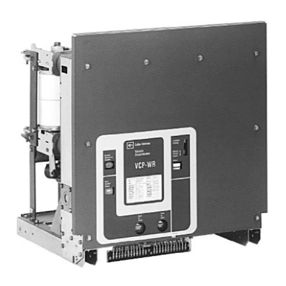
I.B. 8295A61H03 Page 11 cause rusting of metal parts and deterioration of high 3-4 TYPE VCP-WR BREAKER WEIGHTS voltage insulation. A heat level of approximately 400 watts for each 100 cubic feet of volume is recommend- Table 3.1 VCP-WR Breaker Weights (pounds) ed with the heaters distributed uniformly throughout the structure near the floor. - Page 18 I.B. 8295A61H03 Page 12 Secondary Terminal Block Trip Floor Tripper Front Panel Lifting Yoke Opening Escutcheon (Figure 3-7 Close Floor Tripper for Details) Figure 3-1 Front View VCP-WR Series 18 Effective 7/97...
- Page 19 I.B. 8295A61H03 Page 13 Support Insulator Operating Rod Primary Conductor Drive Insulator Interface Flexible Connector Vacuum Interrupter Contact Loading Spring (Wipe Spring) Figure 3-2 Rear View VCP-WR Series 18 Effective 7/97...
- Page 20 I.B. 8295A61H03 Page 14 Secondary Terminal Block (Behind Front Panel) Front Panel Floor Trippers (Behind Front Panel) Lifting Yoke Opening Escutcheon (Figure 3-7 for Details) Figure 3-3 Front View VCP-WR Series 20 Effective 7/97...
- Page 21 I.B. 8295A61H03 Page 15 Support Insulator Primary Conductor Interface Vacuum Interrupter Contact Loading Spring (Wipe Spring) Flexible Connector Figure 3-4 Rear View VCP-WR Series 20 Effective 7/97...
- Page 22 I.B. 8295A61H03 Page 16 Secondary Terminal Block Front Panel Floor Trippers (Not Visible) Lifting Yoke Opening Escutcheon (Figure 3-7 for Details) Figure 3-5 Front View VCP-WR Series 29 Effective 7/97...
- Page 23 I.B. 8295A61H03 Page 17 Standoff Insulator Primary Conductor Interface Vacuum Interrupter Contact Loading Spring (Wipe Spring) Flexible Connector Figure 3-6 Rear View VCP-WR Series 29 Effective 7/97...
-
Page 24: Typical Vcp-Wr Escutcheon
I.B. 8295A61H03 Page 18 Front Panel Operation Counter Nameplate Manual Charge Socket Manual Open Button Open-Closed Indicator Manual Close Button Spring Charged/ Discharged Indicator Figure 3-7 Typical VCP-WR Escutcheon Effective 7/97... -
Page 25: Inspection And Operation
I.B. 8295A61H03 Page 19 SECTION 4: INSPECTION AND crank goes over center with an audible “click” and the springs Charged/ Discharged indicator shows OPERATION “Charged”. 4-1 INITIAL INSPECTION NOTICE Before attempting to use or put a breaker into service, examine it for loose or obviously damaged parts. In addition, compare the breaker nameplate with associat- If the springs are to be charged on a closed breaker, ed drawings, shipping papers and ordering information... -
Page 26: Description And Operation
I.B. 8295A61H03 Page 20 SECTION 5: DESCRIPTION AND used have a proven record for reliability, long life and minimal maintenance (Figures 3-2, 3-4 and 3-6). OPERATION The standard primary insulation used on all VCP-WR Cutler-Hammer Type VCP-WR breaker elements are breaker elements is high strength, flame retardant glass vacuum type interrupting elements designed to offer polyester. -
Page 27: Typical Vcp-Wr Front Mounted Mechanism
I.B. 8295A61H03 Page 21 L. H. Closing Spring Spring Release (Close Coil) Ratchet Wheel Assembly Anti-Pump Relay R. H. Closing Spring Shunt Trip Assembly Auxiliary Switch Opening Spring Charging Motor Motor Cutoff Switch Manual Charge Socket Charging Pawl Closing Cam Operation Counter Figure 5-1 Typical VCP-WR Front Mounted Mechanism Effective 7/97... -
Page 28: 5-2.2 Contact Erosion Indicator
I.B. 8295A61H03 Page 22 5-2.2 CONTACT EROSION INDICATOR The purpose of the contact erosion indicator is to moni- tor any erosion of the vacuum interrupter contacts. Contact erosion is, however, very minimal over time with Cutler-Hammer vacuum interrupters utilizing copper- chrome contact material. -
Page 29: 5-2.3 "T" Cutout Loading Spring Indicator
I.B. 8295A61H03 Page 23 Wipe and Stroke are thus related to each other. As the stroke increases due to the erosion of contacts, the wipe decreases. A great deal of effort has been spent in the design of all Cutler-Hammer vacuum breakers, in order to eliminate the need for field adjustments of wipe or stroke. -
Page 30: 5-3.2 Charging
I.B. 8295A61H03 Page 24 5-3.2 CHARGING Figure 5-6d shows the breaker in the closed position after the closing springs have been recharged. Note that Figure 5-7 is a schematic view of the spring charging the spring charging rotates the closing cam by one half parts of the stored energy mechanism. -
Page 31: Closing Cam And Trip Linkage
I.B. 8295A61H03 Page 25 2 10 Figure 5-6a Breaker open Figure 5-6b Breaker open and closing spring discharged. and closing spring charged. Figure 5-6d Breaker closed Figure 5-6c Breaker closed and closing spring charged and closing spring discharged Pole Shaft Operating Rod Shunt Trip Lever Main Link... -
Page 32: Charging Schematic
I.B. 8295A61H03 Page 26 Breaker Closed, Springs Charged Breaker Open, Springs Discharged Pole Shaft Cam Shaft Anti-Close Interlock Motor Ratchet Lever Spring Release (Close) Latch Drive Pawl Spring Crank Ratchet Wheel Closing Spring Holding Pawl Closing Spring Fixed End Spring Release (Close) Clapper Spring Release (Close) Coil Spring Release Latch (Close Roller) Figure 5-7 Charging Schematic... -
Page 33: 5-4.1 Timing
I.B. 8295A61H03 Page 27 Table 5.1 Breaker Timing Note the position switch (PS1) contact in the spring release circuit in the scheme. This contact remains made while the breaker is being levered between the Event Milliseconds (maximum) TEST and CONNECTED positions for appropriately retrofitted breakers. -
Page 34: Breaker Element Interfacing
I.B. 8295A61H03 Page 28 SECTION 6: BREAKER ELEMENT the appropriate ANSI standard and the specific BIL level of application. The BIL Rating associated with a particu- INTERFACING lar breaker element is clearly indicated on the breaker’s nameplate located on the front cover. 6-1 INTRODUCTION 6-2.2 INTERPHASE BARRIERS WARNING... -
Page 35: 6-2.4 Compartment Interface Verification
I.B. 8295A61H03 Page 29 6-2.4 COMPARTMENT INTERFACE VERIFICATION • Review the Series 18 specific control scheme (Figure 6-2) and the outline drawing (Figures 1-1) presented Refer to paragraph 4-3 in this instruction book for earlier before proceeding. details. 6-3.2 ELECTRICAL INTERFACES 6-3 SERIES 18 BREAKER ELEMENT INTERFACES Secondary control access is provided by 2 12-point sec- The Series 18 breaker element can be used for drawout... -
Page 36: Typical Vcp-Wr "Dc" And "Ac" Control Schematics
I.B. 8295A61H03 Page 30 VCP-WR (18, 20, 29) BREAKER DC CONTROL SCHEMATIC REMOVE JUMPER AND CONNECT ST2 COIL WHEN ST2 OPTION IS USED. SPRING CHARGED 2ND AUXILIARY SWITCH OPTIONAL INDICATING VCP-WR SERIES (18 OR 29) LIGHT 3RD AUXILIARY SWITCH OPTIONAL VCP-WR SERIES (29) MUST ADD JUMPERS AT TERMINAL BLOCK WHEN ST2 OPTION IS USED. -
Page 37: Series 20 Breaker Element Interfaces
I.B. 8295A61H03 Page 31 1. The breaker is held mechanically trip free during rack- Series 18 breaker element (Figure 6-4). An optional ing. The latch check switch is also held open, thus pre- additional top MOC drive is available in the form of a kit venting any electrical close signal from closing the (Style 8794C82G01). -
Page 38: 6-4.2 Electrical Interfaces
I.B. 8295A61H03 Page 32 • Review the details presented in Table 1.1 and Figures • The appropriately sized and secured primary connec- 1-2, 3-3, 3-4, 3-7 and 5-1. tions for fixed or drawout designs. Refer to the follow- ing specific details entitled “Primary Connections.” •... -
Page 39: Series 29 Breaker Element Interfaces
I.B. 8295A61H03 Page 33 as the auxiliary switch contacts in the breaker. The • Review the details presented in Table 1.1 and Figures MOC switch operator is located on the bottom of the 1-3, 3-5, 3-6, 3-7 and 5-1. Series 20 breaker element (Figure 6-6). •... -
Page 40: Series 29 Primary Connection
I.B. 8295A61H03 Page 34 The functions they are intended to perform are as fol- drawing (Figure 1-3) for specific details as to exact loca- lows: tions and the amount of travel associated with each trip- per. 1. The breaker is held mechanically trip free during rack- ing. -
Page 41: Inspection And Maintenance
I.B. 8295A61H03 Page 35 SECTION 7: INSPECTION AND • DO NOT STAND LESS THAN ONE METER AWAY FROM THE BREAKER WHEN TESTING FOR VAC- MAINTENANCE UUM INTEGRITY. 7-1 INTRODUCTION FAILURE TO FOLLOW ANY OF THESE INSTRUC- TIONS MAY CAUSE DEATH, SERIOUS BODILY INJURY, OR PROPERTY DAMAGE. -
Page 42: Inspection And Maintenance Procedures
I.B. 8295A61H03 Page 36 7-3 INSPECTION AND MAINTENANCE PROCEDURES No./Section Inspection Item Criteria Inspection Method Corrective Action 1. Insulation Drive Insulator No dirt Visual Check Clean with lint-free cloth. Molded Pole Unit Support No cracking Visual Check Replace cracked unit Insulation Main Circuit to Ground Withstand... -
Page 43: Vacuum Interrupter Integrity Test
I.B. 8295A61H03 Page 37 7-4 VACUUM INTERRUPTER INTEGRITY TEST Although an ac high potential test is recommended, a dc test may be performed if only a dc test unit is available. Vacuum interrupters used in Type VCP-WR circuit In this case the equipment must be capable of delivering breakers are highly reliable interrupting elements. -
Page 44: Insulation
I.B. 8295A61H03 Page 38 Figure 7-2 Vacuum Interrupter Showing Contact Figure 7-3 Vacuum Interrupter Showing Contact Erosion Indicator with Breaker Open (Shown here for Erosion Indicator with Breaker Closed (Indicators are Clarity Purposes Only). Checked Only When Breaker is Closed). horizontal portion shows with the breaker closed, the mercial equivalent. -
Page 45: Primary Circuit Resistance Check
I.B. 8295A61H03 Page 39 7-9 MECHANISM CHECK Make a careful visual inspection of the mechanism for any loose parts such as bolts, nuts, pins and rings. Check for excessive wear or damage to the breaker components. Operate the breaker several times manu- ally and electrically. -
Page 46: Wipe Indication Procedure
I.B. 8295A61H03 Page 40 ORANGE OR BLACK BLUE OR RED WHITE CONTACT SPRINGS CONTACT SPRINGS CONTACT SPRINGS Any part of Red or Gray Indicator Visible Any part of “T” Shape Indicator Visible Any part of Indicator Visible — “Wipe” Satisfactory —... -
Page 47: Troubleshooting Chart
I.B. 8295A61H03 Page 41 7-11 TROUBLESHOOTING CHART SYMPTOM INSPECTION AREA PROBABLE DEFECTS Fails To Close • Closing Springs not charged • Control Circuit • Control Power (fuse blown or switch off) • Secondary Disconnects • Motor Cut-off Switch (Poor or burned contacts, Lever not operational) •... - Page 48 I.B. 8295A61H03 Page 42 SYMPTOM INSPECTION AREA PROBABLE DEFECTS Fails To Close • Closing Spring charged but • No Closing Sound • Control Power breaker does not close (Close Coil does not pick up) (Fuse blown or switch off) • Secondary Disconnects •...
- Page 49 I.B. 8295A61H03 Page 43 SYMPTOM INSPECTION AREA PROBABLE DEFECTS Fails To Trip • No Trip Sound • Control Circuit • Control Power (Fuse blown or switch off) • Secondary Disconnect • Auxiliary Switch (a contact not making, poor or burned) •...
-
Page 50: Renewal Parts
I.B. 8295A61H03 Page 44 SECTION 8: RENEWAL PARTS 8-2 ORDERING INSTRUCTIONS a. Always specify the breaker rating informotion and 8-1 GENERAL shop order number. In order to minimize production downtime, it is recom- b. Describe the item, give the style number, and specify mended that an adequate quantity of spare parts be car- the quantity required. - Page 51 I.B. 8295A61H03 Page 45 Table 8.1 Recommended VCP-WR Spare Parts (Continued) Description Style Number Style Number Type, Cont. Current, C&L VCP-29WR VCP-29WRSE Interrupter Assembly 50/250, 1200A - 58kA (4”) 3A73901H01 50/250, 1200A - 58kA (4” SC) 3A73901H21 50/250, 2000A - 58kA (5”) 3A73902H01 50/250, 2000A - 58kA (5”...
- Page 52 I.B. 8295A61H03 Page 46 Table 8.1 Recommended VCP-WR Spare Parts (Continued) Description Style Number Style Number Type, Cont. Current, C&L VCP-29WR VCP-29WRSE 75/500, 1200A - 66kA 3A73907H01 3A73907H02 75/500, 2000A - 66kA 3A73908H01 3A73908H02 75/500, 3000A - 66kA 3A73909H01 3A73909H02 150/500, 1200A - 37kA (4”) 3A73910H01 3A73910H02...
- Page 53 I.B. 8295A61H03 Page 47 Table 8.1 Recommended VCP-WR Spare Parts (Continued) Description Style Number Style Number Type, Cont. Current, C&L VCP-29WR VCP-29WRSE 150/750, 1200A - 58kA 3A73913H01 3A73913H02 150/750, 2000A - 58kA 3A73914H01 3A73914H02 150/750, 3000A - 58kA 3A73915H01 3A73915H02 150/1000, 1200A - 77kA 3A73916H01 3A73916H02...
- Page 54 I.B. 8295A61H03 Page 48 Table 8.1 Recommended VCP-WR Spare Parts (Continued) Description Style Number Style Number Type, Cont. Current, C&L VCP-29WR VCP-29WRSE 150/63, 1200A - 101kA 3A73916H31 150/63, 2000A - 101kA 3A73917H31 150/63, 3000A - 101kA 3A73918H31 Description Style Number Type, Cont.
- Page 55 I.B. 8295A61H03 Page 49 Table 8.1 Recommended VCP-WR Spare Parts (Continued) Description Style Number Type, Cont. Current, C&L VCP-18WR 50/250, 1200A - 58kA 3A73923H01 50/350, 1200A - 78kA 3A73932H01 50/250, 2000A - 58kA 3A73924H01 50/350, 2000A - 78kA 3A73933H01 75/500, 1200A - 66kA 3A73925H01 75/500, 2000A - 66kA 3A73926H01...
- Page 56 I.B. 8295A61H03 Page 50 Table 8.1 Recommended VCP-WR Spare Parts (Continued) Description Style Number Type, Cont. Current, C&L VCP-18WR 150/500, 2000A - 37kA 3A73929H01 150/750, 1200A - 58kA 3A73930H01 150/750, 2000A - 58kA 3A73931H01 Style Number Style Number Description VCP-29WR VCP-29WRSE Phase Barriers Up to 15kV...
- Page 57 I.B. 8295A61H03 Page 51 Table 8.1 Recommended VCP-WR Spare Parts (Continued) Style Number Style Number Description VCP-29WR VCP-29WRSE Push Rod Assemblies Up to 5kV 692C799G01 BLUE SPRINGS Up to 5kV 692C799G02 RED SPRINGS Up to 15kV 691C650G01 691C650G02 WHITE SPRINGS Up to 15kV 691C651G01 691C651G02...
- Page 58 I.B. 8295A61H03 Page 52 Table 8.1 Recommended VCP-WR Spare Parts (Continued) Style Number Style Number Description VCP-29WR VCP-29WRSE Lower Support Up to 15kV 5697B19H01 686C575H01 350, 1000MVA 1200, 2000A Shock Absorber Up to 15kV 5677B26H01 5677B26H01 350, 1000MVA 1200, 2000A 63kA Style Number Description...
- Page 59 I.B. 8295A61H03 Page 53 Table 8.1 Recommended VCP-WR Spare Parts (Continued) Style Number Description VCP-20WR Tie Bars Up to 5kV 690C818H01 Style Number Description VCP-18WR Phase Barriers Up to 15kV 5677B34H01 (except) 50/350, 1200A/2000A 5677B36H01 Shock Absorber 5677B26H01 Style Number Description VCP-29WR VCP-29WRSE...
- Page 60 I.B. 8295A61H03 Page 54 Table 8.1 Recommended VCP-WR Spare Parts (Continued) Style Number Description VCP-29WR VCP-29WRSE VCP-20WR VCP-18WR Motor Brush Kit 8063A77G01 8063A77G01 8063A77G01 8063A77G01 Spring Release Coils 48DC 3759A76G11 3759A76G11 3759A76G11 3759A76G11 125VDC/120VAC 3759A76G12 3759A76G12 3759A76G12 3759A76G12 250VDC/240VAC 3759A76G13 3759A76G13 3759A76G13 3759A76G13 Rectifier 120/240VAC...
- Page 61 I.B. 8295A61H03 Page 55 Table 8.1 Recommended VCP-WR Spare Parts (Continued) Style Number Description VCP-29WR VCP-29WRSE VCP-20WR VCP-18WR Motor Cutoff Switch 699B199G04 699B199G04 699B199G04 Motor Cutoff Switch 5677B02G11 Latch Check Switch 699B147G01 699B147G01 699B147G01 699B147G01 Position Switch 1 699B147H01 699B147H01 699B147H01 699B147H01 Position Switch 2 3759A93H02 3759A93H02 3759A93H02 3759A93H02 Auxiliary Switch...
- Page 62 I.B. 8295A61H03 Page 56 Table 8.1 Recommended VCP-WR Spare Parts Style Number Description VCP-29WR VCP-29WRSE VCP-20WR VCP-18WR Trip Latch 699B040G03 699B040G03 699B040G03 699B040G03 (Hatchet) Open Closed Discharged Push to Open Labels Kit 8295A45G01 8295A45G01 8295A45G01 8295A45G01 Charged Push to Close VCP-WR Field Style Number Installation Kit...
- Page 63 I.B. 32-255-1E This instruction booklet is published solely for informa- tion purposes and should not be considered all inclu- sive. If further information is required, you should con- sult Cutler-Hammer. Sale of product shown in this literature is subject to terms and conditions outlined in appropriate Cutler- Hammer selling policies or other contractual agreement between the parties.
Need help?
Do you have a question about the Cutler-Hammer VCP-WR 18 Series and is the answer not in the manual?
Questions and answers