Eaton Cutler-Hammer Digitrip 1150 Instructions Manual
Trip units for use only in cutler-hammer magnum and magnum ds circuit breakers
Hide thumbs
Also See for Cutler-Hammer Digitrip 1150:
- Instruction manual (10 pages) ,
- Instructions manual (71 pages)
Table of Contents
Advertisement
I.L. 70C1036H05
Instructions for Digitrip Models 1150, 1150i and 1150
+
1150
i Trip Units for use only in Cutler-Hammer Magnum
and Magnum DS Circuit Breakers
Table of Contents
1.0 General Description of Digitrip Trip Units ................. 7
1.1 Protection ............................................................... 7
1.2 Mode of Trip and Status Information ........................ 7
1.3 Installation and Removal .......................................... 7
1.3.1 Installation of the Trip Unit ............................ 7
1.3.2 Rating Plug Installation ................................. 8
1.3.3 Trip Unit/Rating Plug Removal ....................... 9
1.4 Wiring ..................................................................... 9
1.5 Plexiglass Cover ..................................................... 9
1.6 DT 1150 Power/Relay Module .................................. 9
1.6.1 Auxiliary Power ............................................. 9
1.6.2 Alarm Contacts ............................................. 9
1.7 Standards .............................................................. 10
2.0 Description of Magnum Circuit Breakers ............... 10
2.1 General ................................................................. 10
2.2 Low-Energy Trip Actuator ...................................... 11
2.3 Ground Fault Protection ........................................ 11
2.3.1 General ....................................................... 11
2.3.2 Residual Sensing (3 Wire or 4 Wire) ........... 12
2.3.3 Source Ground Sensing .............................. 12
2.3.4 Zero Sequence Sensing .............................. 12
2.3.5 Multiple Source/Multiple Ground ................. 12
2.3.6 Ground Fault Settings ................................. 12
2.4 Current Sensors for Standard Breaker .................. 13
2.5 Current Sensors for Double Wide Breaker ............ 13
3.0 Principles of Operation .......................................... 13
3.1 General ................................................................. 13
3.2 Trip and Operation Indicators ................................. 13
3.2.1 Status/Long Pickup LED ............................. 13
3.2.2 Alarm LED .................................................. 14
3.2.3 Trip LED ..................................................... 14
3.3 Making Current Release ........................................ 14
3.4 Zone Interlocking ................................................... 14
3.5 PT Module ............................................................ 14
4.0 Programming/Viewing Digitrip 1150 ....................... 19
4.1 Main Menu ............................................................ 19
4.1.1 Power Up Sequence ................................... 19
4.1.2 Pushbutton Definition .................................. 19
4.1.3 Blink Mode ................................................. 22
4.1.4 Programming/Viewing Screens ................... 22
4.2 Program Settings PGM SET ................................. 22
Pickup/Time Settings ................................. 22
4.2.3 INCOM Communications .......................... 28
4.2.4 Aux RELAYS .............................................. 28
4.2.5 ALARMS .................................................... 28
Effective 10/2004
Courtesy of NationalSwitchgear.com
4.2.6 Digital Relay Accessory Module ................. 28
4.2.7 TripLink ....................................................... 30
4.2.8 Setting TIME ............................................... 31
4.2.9 Selecting DISPLAYS .................................. 31
4.2.10 SYSTEM Settings ...................................... 31
4.3 View Settings (VIEW SET) .................................... 31
4.3.1 Firmware Menu ........................................... 31
4.4 METER Menu ....................................................... 31
4.5 HARMONIC Menu ................................................. 32
4.6 EventLOG ............................................................. 32
4.7 Power and Energy Parameters .............................. 32
4.8 Power Quality ....................................................... 33
4.8.1 Power Factor, THD and Crest Factor .......... 33
4.8.2 Alarms ........................................................ 33
4.9 WAVEFORM CAPTURE Feature .......................... 33
4.9.1 Six Cycle Waveform Capture on Trip ........... 33
4.9.2 One Cycle Waveform Capture ..................... 33
4.10 HEALTH ................................................................ 33
5.0 Test Procedures .................................................... 34
5.1 General ................................................................. 34
5.2 When to Test ........................................................ 34
5.2.1 Self Testing ................................................. 34
5.2.2 Functional Field Testing .............................. 35
5.3.1 Code Requirements .................................... 35
5.3.2 Standard Requirements .............................. 36
5.3.3 General Test Instructions ............................ 36
6.0 Battery .................................................................. 37
6.1 General ................................................................. 37
6.2 Battery Test .......................................................... 37
6.3 Battery Installation and Removal ........................... 37
(Sensor Ratings and Rating Plugs) ........................ 38
8.0 Record Keeping .................................................... 38
9.0 References ............................................................ 39
9.1 Magnum and Magnum DS Circuit Breakers ........... 39
9.2 Time-Current Curves .............................................. 39
Appendix A Zone Interlocking Examples ....................... 43
Appendix B Troubleshooting Guide ............................... 45
Connection Diagram .............................................. 47
Appendix D Display Menu Diagrams ............................. 48
Appendix E Display Abbreviations ................................. 76
Appendix F Digitrip Settings and Descriptions .............. 78
Appendix G Auxiliary Relays ........................................ 81
Appendix H Digital Relay Accessory Module ................ 82
Appendix I Modbus Translator Wiring ........................ 83
I.L. 70C1036H05
Page 1
+
,
Advertisement
Table of Contents

Related Manuals for Eaton Cutler-Hammer Digitrip 1150


Summary of Contents for Eaton Cutler-Hammer Digitrip 1150
-
Page 1: Table Of Contents
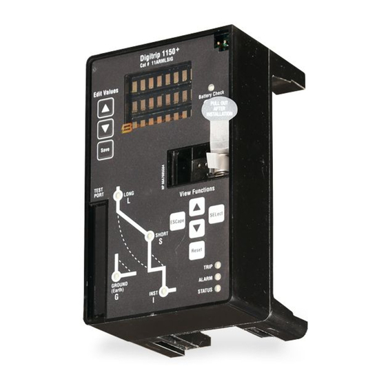
I.L. 70C1036H05 I.L. 70C1036H05 Page 1 Instructions for Digitrip Models 1150, 1150i and 1150 1150 i Trip Units for use only in Cutler-Hammer Magnum and Magnum DS Circuit Breakers Table of Contents 1.0 General Description of Digitrip Trip Units ....7 4.2.6 Digital Relay Accessory Module .... - Page 2 I.L. 70C1036H05 Page 2 Figure 1.1 Digitrip 1150 Catalog # 11PLSIG Trip Unit with Rating Plug WARNING WARNING DO NOT ATTEMPT TO INSTALL OR PERFORM OBSERVE ALL RECOMMENDATIONS, NOTES, CAU- MAINTENANCE ON EQUIPMENT WHILE IT IS TIONS, AND WARNINGS RELATING TO THE SAFETY ENERGIZED.
- Page 3 I.L. 70C1036H05 Page 3 Table 1.1a CURRENT Protection Functions for Digitrip 1150/1150i Trip Trip Unit Type Digitrip 1150 Digitrip 1150i Ampere Range 100A-6000A 200A-6300A RMS Sensing Protection and Coordination Protection Ordering Options Catalog # 11LSI, 11LSIG, 11LSIA or 11IEC, 11IEC-EF or 11PLSI, 11PLSIG, 11PLSIA 11PIEC, 11PIECEF Fixed Rating Plug (I...
- Page 4 I.L. 70C1036H05 Page 4 Table 1.1b Metering Data for Digitrip 1150/1150i Trip Units Current Metering Units Tolerance Notes IA, IB, IC, IN, Amperes ±1% FS Real time data, FS = In rating Amperes ±2% FS Real time data, FS = In rating IA, IB, IC (AVG) Amperes 5 MINUTE AVERAGE...
- Page 5 I.L. 70C1036H05 Page 5 Table 1.1c Power Quality Data for Digitrip 1150/1150i Trip Units Harmonic Units Notes THD (Total Harmonic Distortion) THDA 0 to 99 percent Phase A current THDB 0 to 99 percent Phase B current THDC 0 to 99 percent Phase C current THDN 0 to 99 percent...
- Page 6 I.L. 70C1036H05 Page 6 Table 1.1d VOLTAGE PROTECTION functions for Digitrip 1150/1150i Trip Units Trip Unit Type Digitrip 1150 Digitrip 1150i Ordering Catalog Number 11PLSI, 11PLSIG, 11PLSIA 11PIEC, 11PIECEF SYSTEM Frequency 50 or 60 Hz 50 or 60 Hz TRIPS RANGE STEP SIZE TOLERANCE...
-
Page 7: General Description Of Digitrip Trip Units
I.L. 70C1036H05 Page 7 If you have any questions or need further information or The Digitrip 1150 family of trip units provides five phase and instructions, please contact your local representative or two ground (time-current) curve-shaping adjustments. To satisfy the protection needs of any specific installation, the the Cutler Hammer Customer Support Center. -
Page 8: Rating Plug Installation
I.L. 70C1036H05 Page 8 Figure 1.2 Installation of the Digitrip Unit into a Magnum Circuit Breaker (Side View) OPEN CIRCUIT CONDITION. THERE IS NO PROTEC- Before plugging into the black edge connector, align the TION FOR THE LOAD CIRCUIT. long pins on the bottom of the Digitrip into the white, I1, connector (See Figure 1.2). -
Page 9: Trip Unit/Rating Plug Removal
I.L. 70C1036H05 Page 9 To remove the trip unit from the circuit breaker, deflect the top and bottom spring clips to release the unit from the black mounting platform. Pull the unit to disengage the trip unit’s printed circuit board connectors J0 & I1 from the circuit breaker (See Figure 1.2 and Appendix C). -
Page 10: Standards
I.L. 70C1036H05 Page 10 function is enabled by programming the Aux Relay B via the front panel or via PowerNet communication (See Appendix D-15). The block close function can be further setup for “AUTO” or “MANUAL” reset via programming (11Pxxx only). This trip condition requires a front panel reset to clear the Block Close condition. -
Page 11: Low-Energy Trip Actuator
I.L. 70C1036H05 Page 11 functions of the Digitrip Trip Unit are performed by its spring and a coil. Nominal coil resistance is 24 ohms and internal circuitry. There is no mechanical or direct mag- the black lead is positive. The circuit breaker mechanism netic action between the primary current and the mechani- assembly contains a mechanism-actuated reset lever and cal tripping parts of the circuit breaker, thus external... -
Page 12: Residual Sensing (3 Wire Or 4 Wire)
I.L. 70C1036H05 Page 12 the circuit breaker is applied to the system. These ele- 2.3.3 Source Ground Sensing ments are discussed in Sections 2.3.3 through 2.3.6. Depending upon the installation requirements, alternate ground fault sensing schemes may be dictated (See The Digitrip 1150 family uses three modes of sensing to Figures 2.6 and 2.7). -
Page 13: Current Sensors For Standard Breaker
I.L. 70C1036H05 Page 13 breaker rating (In). For example, 2000A:1A sensors are circuit breaker if the chip temperature is excessive. If the used on a 2000A rated circuit breaker. There are also four unit trips on over-temperature, the red Long Delay Time auxiliary current transformers with a ratio of 10:1 which LED will flash and the OVER TEMP TRIP message will further step down the rated current to 100 milliamperes,... -
Page 14: Alarm Led
I.L. 70C1036H05 Page 14 trip unit is energized and operating properly (See Figure wireslabeled Zone In (Zin) and Zone Out (Zout) along with a 3.1). Zone Common wire. The Zone Selective Interlocking function combines the interlocking of Short Delay and Ground Fault. - Page 15 I.L. 70C1036H05 Page 15 Source Black Trip Actuator Digitrip with GF 10:1 10:1 AUX. CT Load Notes: In this scheme, all breaker secondary currents (at the 100mA level) are summed together at the pc board donut transformer to sense ground fault via element R 5 . No jumper on secondary contacts B-6, B-7.
- Page 16 I.L. 70C1036H05 Page 16 Figure 2.4 Digitrip Neutral Sensor Types This will defeat all ground fault protection in application for 4 pole breaker. Figure 2.5 4-Pole-3200A Standard Circuit Breaker Using Residual Ground Fault (Earth-Fault) Sensing Effective 10/2004 Courtesy of NationalSwitchgear.com...
- Page 17 I.L. 70C1036H05 Page 17 1150 Figure 2.6 Source Ground Fault Sensing Scheme for Standard Circuit Breaker Notes: 1 In this scheme, the current sensors in the circuit breaker poles are parallel-wired to achieve a 4000 Amp circuit breaker rating. The ground fault is sensed directly via element R . jumper is required on B-6, B-7 secondary contacts to program the Digitrip 1150 to use element R directly for source ground sensing.
- Page 18 I.L. 70C1036H05 Page 18 If the breaker is removed from cell (B-6,B-7) jumper disconnected, Residual Ground settings will apply. Figure 2.8 Zero Sequence Sensing Scheme for Standard Circuit Breaker φ φ I /2 I /2 I /2 I /2 i /2 i /2 i /2 Internal...
-
Page 19: Programming/Viewing Digitrip 1150
Edit Values settings, the display will alternate between “Customer Settings in Use” and “Eaton-Electrical DT 1150” mes- The “Edit Values” group located in the upper left hand sages. Following this the display will enter into the main corner of the Digitrip 1150 unit consists of 3 pushbuttons: menu (See Appendix D-1). - Page 20 I.L. 70C1036H05 Page 20 Figure 3.1 Digitrip 1150 Block Diagram with Circuit Breaker Interface Effective 10/2004 Courtesy of NationalSwitchgear.com...
- Page 21 I.L. 70C1036H05 Page 21 Figure 3.2 Digitrip 1150 LSI Figure 3.3 Digitrip 1150 LSIA Figure 3.4 Digitrip 1150i IEC Figure 3.5 Digitrip 1150i IEC-EF Effective 10/2004 Courtesy of NationalSwitchgear.com...
-
Page 22: Blink Mode
I.L. 70C1036H05 Page 22 timestamp of event and view down to observe TEST Menu. When prompted, pressing Save will begin the trip current data. This data, along with selected test. timestamp will also be stored in Event Log. The maximum trip current value that can be Battery Test - The Battery Test pushbutton is located on the right side of the Digitrip 1150 unit, just above the rating displayed is 65535 A. - Page 23 I.L. 70C1036H05 Page 23 NOTE: (Ir) is also the basis for the Short Delay Current The installed rating plug must match the current sensors Setting (See Section 4.4). which establish the maximum continuous current rating of the circuit breaker (In). Instantaneous and ground current settings are defined in multiples of (In).
- Page 24 I.L. 70C1036H05 Page 24 current returns to normal, the LTM begins to reset; after about 10 minutes it will have reset fully, so the next Long Delay trip time will again correspond to the Setting value. Short Delay NOTE: In certain applications and field testing, it may be Time desirable to disable the LTM function by disabling this .4 Sec.
- Page 25 I.L. 70C1036H05 Page 25 again, so that a sputtering fault may not be detected. With the GROUND FAULT MEMORY function, the trip unit Available Settings Inst. “remembers” the sputtering ground current for up to ten 2, 2.5, 3, ... x n I (10) times the Ground Fault Time Setting.
-
Page 26: Voltage - Frequency, Reverse Power
I.L. 70C1036H05 Page 26 4.2.1.10.2 Phase Loss - (Current Based) main conductors at the top of the circuit breaker. This is the factory wired setup. A factory option does exist to enable bottom end of circuit breaker sensing of voltage. The phase loss trip function can be selected in the Pro- gram Settings - Program Curve Menu (See Appendix D- 12). - Page 27 I.L. 70C1036H05 Page 27 EXAMPLE 1 (Assumes line to line voltage > 84V) ProGRam SETting SYSTEM FREQ 60Hz VOLTAGE VOLTAGE SETTINGS ENABLED UnderFREQ TRIP 58.0Hz ALARMS UndrFREQ ALARM 59.0Hz AuxReLaY A RELAY A UF ALARM ENABLED Applied Freq. TRIP UF ALARM FREQ OUT OF BOUNDS ALARM RELAY A Operation 1 to 50.8...
-
Page 28: Incom Communications
I.L. 70C1036H05 Page 28 4.2.3 INCOM The Digitrip 1150 will light the red LED shown in Figure 1.1 when transmitting on INCOM. INCOM programming (See Appendix D-11) allows for five different setting options. These include address (001 – Recommended cable specifications: FFE in hexadecimal form), baud rate (9600 or 1200), and enabling or disabling external communications trip (EXT •... - Page 29 I.L. 70C1036H05 Page 29 Typical IBM Compatible Computer Breaker Interface Monitor ΙΙ (BIM ) See View A Twisted Pair. No. 18 AWG. Cut-off Shield or connect to unused customer terminal -- Do not Ground. Typical Magnum Circuit Breaker with Digitrip Trip Unit Baud Rate 1200 or 9600 0 0 1...
-
Page 30: Triplink
I.L. 70C1036H05 Page 30 Figure 4.9 TripLink Transfer 4.2.7 TripLink TripLink is a means of transferring settings from one circuit NOTE: A TripLink cable when installed will disconnect that breaker to another. TripLink transfers all protection settings unit from the INCOM communication network. and time and date, and the circuit breaker’s circuit data. -
Page 31: Setting Time
I.L. 70C1036H05 Page 31 2. To send settings, the receiving circuit breaker must be perameters can be set to on or off, depending on user in open state and without line voltage on the circuit preference. Any settings turned to OFF will not be dis- breaker’s main terminals. -
Page 32: Harmonic Menu
I.L. 70C1036H05 Page 32 and alarm events the per harmonic analysis is not pro- in Appendix D-14 and D-3. vided. PowerNet software screens are available to show waveform capture oscillographs of each phase as well as The Demand and the average, minimum and maximum bar graphs of the magnitudes and individual harmonics that current screens alternate between the data and additional make up the three-phase currents (See Section 4.9). -
Page 33: Power Quality
I.L. 70C1036H05 Page 33 source ground configuration). A total of 58 data points per The Auxiliary ReLaY A can be assigned to a Pulse Initiator phase per cycle is captured and can be sent to a host function for either kVAh or kWh. When this feature is computer. -
Page 34: Test Procedures
I.L. 70C1036H05 Page 34 The type of data includes the total number of all Instanta- CAUTION neous and Short Delay trips seen by the circuit breaker. A second counter shows the number of Overloads (LDT) TESTING A CIRCUIT BREAKER WHILE IT IS IN-SER- and Ground Faults (GFT) encountered while in service. -
Page 35: Self Testing
I.L. 70C1036H05 Page 35 5.2.1 Self Testing testing can determine the accuracy of the desired trip settings by performing Long Delay, Short Delay, and Prior to any self testing, the plexiglass cover will need to Ground Fault functional tests. The Cutler-Hammer-ap- be removed. -
Page 36: Standard Requirements
I.L. 70C1036H05 Page 36 5.3.2 Standard Requirements Apply the same current as described above through one phase of the circuit breaker, returning through the neutral As a follow-up to the basic performance requirements sensor. The circuit breaker should not trip, and the alarm stipulated by the NEC, UL Standard No. -
Page 37: Battery
I.L. 70C1036H05 Page 37 6.2 Battery Test Primary Disconnect The battery is a long-life, lithium, camera-type unit. Check Stabs - When Suitable the status of the battery at any time by pressing the Drawout Conductors Battery Test pushbutton and observing the green LED. If the Battery Test LED does not light green, replace the battery. -
Page 38: Frame Ratings (Sensor Ratings And Rating Plugs)
I.L. 70C1036H05 Page 38 OPEN. ACCIDENTALLY INSTALLING THE BATTERY IN 1. The Instantaneous and Ground Current Settings (if THE REVERSE DIRECTION WILL NOT HARM EITHER provided) are multiples of (In) (See Sections 4.2.1.6 THE TRIP UNIT OR THE BATTERY, BUT WILL DEFEAT and 4.2.1.7). -
Page 39: References
I.L. 70C1036H05 Page 39 9.0 REFERENCES 9.1 Magnum and Magnum DS Circuit Breakers I.B. 2C12060 Magnum DS Circuit Breaker Instructions I.B. 2C13060 Magnum I. Circuit Breaker Instructions 4A36346 Zone Interlocking Application with Non- Magnum Circuit Breakers I.L 70C1143 Installation Instructions for Digital Relay Accessory Module I.L. - Page 40 I.L. 70C1036H05 Page 40 DIGITRIP TRIP FUNCTION SETTINGS Circuit No./Address Breaker Shop Order Reference PER UNIT MULTIPLIERS Rating Plug Amperes Ir Continuous Ampere Rating (In) = LDS x In Ampere Trip Per Unit Equivalent Function Setting Multi Setting Time Delay Inst.
- Page 41 I.L. 70C1036H05 Page 41 DIGITRIP AUTOMATIC TRIP OPERATION RECORD Circuit No./Address Circuit Breaker Shop Order Reference Trip Function Settings Reference Factory Rev. 1 Rev. 2 Rev. 3 Curve Type LSIG* Slope Ir = Long PU x ln Long Time Long Memory Short Slope FLAT Short PU x Ir...
- Page 42 I.L. 70C1036H05 Page 42 GROUND FAULT TEST RECORD FORM Ground Fault Test Record should be retained by those in charge of the building's electrical installation in order to be available to the authority having jurisdiction. Test Date Circuit Breaker Results Tested by Number Figure 8.3 Typical Performance Test Record Form...
-
Page 43: Appendix A Zone Interlocking Examples
I.L. 70C1036H05 Page 43 APPENDIX A Zone Interlocking Examples Fault at location 2 The feeder circuit breaker trip unit will initiate the trip in 0.045 seconds to clear the fault and will send an interlock- ing signal to the main trip unit. The main trip unit will begin to time out and, in the event that the feeder circuit breaker NOTICE Z2 does not clear the fault, the main circuit breaker will... - Page 44 I.L. 70C1036H05 Page 44 Notes: Wiring to be twisted pair of AWG #14 to #20. Route 1600A Main Zone Interlocking wiring separate from power conductors. DO NOT GROUND any Zone Interlocking wiring. Zone 0.5 Sec The maximum distance between two farthest circuit breakers 1200A on different zones (from the ZO downstream to ZI upstream terminals) is 250 feet (76m).
-
Page 45: Appendix B Troubleshooting Guide
I.L. 70C1036H05 Page 45 Appendix B Troubleshooting Guide Symptom Probable Cause Possible Solution(s) Comments LED display is not energized. No auxiliary power input. Wrong auxiliary power Check voltage input terminals A14-A15. Refer to Section 1.6.1. voltage. As soon as current starts to Rating plug is not installed Install rating plug and/or check for loose or is loose. - Page 46 I.L. 70C1036H05 Page 46 Appendix B Troubleshooting Guide Continued Symptom Probable Cause Possible Solution(s) Comments SETTINGS Set point mismatch Enter Program Settings by using the Esc If alarm reappears after trying the possible solution, ERROR between CHip A and CHip Button (do not use Reset Button) and SAVE replace trip unit at first opportunity.
-
Page 47: Appendix C Typical Breaker Master Connection Diagram
I.L. 70C1036H05 Page 47 Appendix C Typical Circuit Breaker Master Connection Diagram Effective 10/2004 Courtesy of NationalSwitchgear.com... -
Page 48: Appendix D Display Menu Diagrams
I.L. 70C1036H05 Page 48 Appendix D - Display Menu Diagrams Appendix D - Page D-1 Startup CHANGE Sequence FACTORY SETUP? EATON FACTORY Program Factory Settings ELECTRIC SETTINGS Current Curve Page D-23 (Page D-12) DT 1150 IN USE If any current curve setting (shown on pages D-12 and... - Page 49 I.L. 70C1036H05 Page 49 Appendix D - Display Menu Diagrams Continued Appendix D - Page D-2 Meter Menu Individual screens are only displayed if their Display Setting is set to "ON". If "AUTO" is set in IA XXXXX Display Settings IA IB IC IA XXXXX IN IG...
- Page 50 I.L. 70C1036H05 Page 50 Appendix D - Display Menu Diagrams Continued Appendix D - Page D-3 Event Log Menu When a trip event occurs, data from the appropriate Meter Menu screens is captured and then logged for that event. The event numbering scheme is a first-in, first-out type.
- Page 51 I.L. 70C1036H05 Page 51 Appendix D - Display Menu Diagrams Continued Appendix D - Page D-4A Possible Events Note: "Meter screens" refer to those on D-2 TRIP Data and Time Stamp logged for each event. 1st & 2nd LONG OVER L-L Voltage and UndrFREQ No data...
- Page 52 I.L. 70C1036H05 Page 52 Appendix D - Display Menu Diagrams Continued Appendix D - Page D-4B Possible Events Note: "Meter screens" refer to those on D-2 Alarms Data logged and shown Alarm screens will be real-time messages for each event. Additional Alarms for Cat # 1 1PXXX only LDPU (LONG Pickup)
- Page 53 I.L. 70C1036H05 Page 53 Appendix D - Display Menu Diagrams Continued Appendix D - Page D-5 View Settings Menu VOLTAGE View Current CURRENT ESC / SEL Curve (Page D-6) SYSTEM VIEW CURRENT FREQ BC RELAY SLIDING WAVEFORM SYSTEM RESET DEMAND CAPTURE DISPLAY XXHz...
- Page 54 I.L. 70C1036H05 Page 54 Appendix D - Display Menu Diagrams Continued Appendix D - Page D-6 Selected curve and trip style View Current determines the menus shown. The Settings user can only view the curve set in LSIG or LSI Program Settings Menu.
- Page 55 I.L. 70C1036H05 Page 55 Appendix D - Display Menu Diagrams Continued Appendix D - Page D-7 View Display Settings IA IB IC IN IG IA IB IC AVERAGE Max rms XXXXXX VIEW IN IG IA IB IC IN IG AVERAGE Max rms PF Hz IA IB IC...
- Page 56 I.L. 70C1036H05 Page 56 Appendix D - Display Menu Diagrams Continued Appendix D - Page D-8 View Auxiliary " * " (asterisk) is placed beside Relay Menu the relay letter when at least one of its RELAY functions is Group 1 Group 2 ENABLED.
- Page 57 I.L. 70C1036H05 Page 57 Appendix D - Display Menu Diagrams Continued Appendix D - Page D-9 View Alarms GROUND ALARM TO VOLT UN- ALARM EventLOG ALARM BALANCE XXXX A XXXXXXXX XXXXXX XXX S VIEW NEUT AMP ALARM ON ALARM ALARM TIME XXXX A XXX S...
- Page 58 I.L. 70C1036H05 Page 58 Appendix D - Display Menu Diagrams Continued Appendix D - Page D-10A View Accessory Bus Settings NO SETTINGS If no relay functions are enabled Save Each of the 4 addresses "XXXXXXXX = is a separate Save group (Page D-19) XXXXXXXX "...
- Page 59 I.L. 70C1036H05 Page 59 Appendix D - Display Menu Diagrams Continued Appendix D - Page D -10B View VOLTAGE VOLTAGE ENABLED SETTING DISABLED XXXXXXX UndrVOLT VOLT UN- TRIP BALANCE XXX V XXX s VIEW UndrVOLT VOLT UN- TIME BALANCE XXX s XX % OverVOLT RevPower...
- Page 60 I.L. 70C1036H05 Page 60 Appendix D - Display Menu Diagrams Continued Appendix D - Page D-11 Program Settings VOLTAGE Program Current CURRENT Menu ESC / SEL Curve (Page D-6) SYSTEM Program CURRENT FREQ BC RELAY SLIDING WAVEFORM SYSTEM RESET DEMAND CAPTURE DISPLAY Manual,...
- Page 61 I.L. 70C1036H05 Page 61 Appendix D - Display Menu Diagrams Continued Appendix D - Page D-12 Program Current Curve 11LSIG or 11IEC-EF or IEEE/IEC 11PLSIG 11PIECEF Catalog # Catalog # IEEE Program LSIG LSIG LSIG Curve Represents the active (Page D-13) XX = curve.
- Page 62 I.L. 70C1036H05 Page 62 Appendix D - Display Menu Diagrams Continued Appendix D - Page D-13 Program CURRENT Save Curve (Page D-19) LSI-G LONG PHASE 1 - 30 s SLOPE LOSS (steps of 1 s) VIEW LONG PU AMP UN- Screen is skipped if 0 - 240 s first AMP UN-...
- Page 63 I.L. 70C1036H05 Page 63 Appendix D - Display Menu Diagrams Continued Program Appendix D - Page D-14 Display Settings Save (Page D-19) IA IB IC IN IG IA IB IC AUTO AVERAGE Max rms MANUAL VIEW IA IB IC IN IG AVERAGE Max rms IN IG...
- Page 64 I.L. 70C1036H05 Page 64 Appendix D - Display Menu Diagrams Continued Appendix D - Page D-15 Program Aux Relays Menu " * " (asterisk) is placed beside the relay letter when at least one of its RELAY Group 1 functions is ENABLED. Group 2 RELAY C* PULSE...
- Page 65 I.L. 70C1036H05 Page 65 Appendix D - Display Menu Diagrams Continued Appendix D - Page D-16 Program Save Alarms (Page D-19) GROUND OverVOLT UndrFREQ 0.10 to 1.00, 1200A Max 1 to 250s ALARM TIME ALARM IEEE 58 to 62 (60Hz) or (steps of 1s) .
- Page 66 I.L. 70C1036H05 Page 66 Appendix D - Display Menu Diagrams Continued Appendix D - Page D-17A Program Accessory Bus NO SETTINGS If no relay functions are enabled Save Each of the 4 addresses is "XXXXXXXX = a separate Save group (Page D-19) XXXXXXXX "...
- Page 67 I.L. 70C1036H05 Page 67 Appendix D - Display Menu Diagrams Continued Appendix D - Page D-17B Program VOLTAGE VOLTAGE ENABLED * SETTING DISABLED UndrVOLT VOLT UN- 90 t0 670V TRIP BALANCE 1 to 250s (steps of 1V) VIEW UndrVOLT VOLT UN- 5% to 50% TIME BALANCE...
- Page 68 I.L. 70C1036H05 Page 68 Appendix D - Display Menu Diagrams Continued Appendix D - Page D-18 Program Program Settings Menu TripLink TripLink To Program CONFIG Settings Menu ERROR YES if... Receiving circuit breaker is open THIS PRESS Alternate screen that will BREAKER SAVE flash on for a short time.
- Page 69 I.L. 70C1036H05 Page 69 Appendix D - Display Menu Diagrams Continued Appendix D - Page D-19 Save Save SETTINGS SAVE Savable Previous ESC OR (TIMEOUT) TRANSFER XXXXXXXX Data Menu SAVE Level ERROR Screen XXXXXXXX (AUTO) SAVE SETTINGS TRANSFER SAVING COMPLETE Transfer Successful? SAVE...
- Page 70 I.L. 70C1036H05 Page 70 Appendix D - Display Menu Diagrams Continued Appendix D - Page D-20 Test Menu NOTE: If LSI curve is selected, GND TEST will not be available. Current Testing PH TEST TRIP GND TEST ESC / SEL NON-TRIP GND TEST 0.1 to 2.0...
- Page 71 I.L. 70C1036H05 Page 71 Appendix D - Display Menu Diagrams Continued Appendix D - Page D-21 Harmonics Menu HARMON N THDA XX% THDB XX% VIEW THDA XX% THDB XX% THDC XX% THDB XX% HARMON C THDC XX% HARMON N THDN XX% THDA XX% HARMON X THDC XX%...
- Page 72 I.L. 70C1036H05 Page 72 Appendix D - Display Menu Diagrams Continued Multiple Appendix D - Page D-22 Alarm Screens MULTIPLE XXXX XXXX XXXX ALARMS ALARM ALARM ALARM View 1st meter screen (if applicable) View 2nd meter screen (if applicable) * Note: If more than one alarm condition exists in the system, the "Mutliple Alarm"...
- Page 73 I.L. 70C1036H05 Page 73 Appendix D - Display Menu Diagrams Continued Appendix D - Page D-23 Program VOLTAGE ENABLED * SETTING VOLTAGE DISABLED UndrVOLT 90 t0 670V VOLT UN- TRIP BALANCE 1 to 250s (steps of 1V) VIEW UndrVOLT VOLT UN- 5% to 50% TIME BALANCE...
- Page 74 I.L. 70C1036H05 Page 74 Appendix D - Display Menu Diagrams Continued Appendix D - Page D-24 HEALTH TRIPUNIT TRIPUNIT RESET MAX TEMP RESET RESET MAX TEMP VALUE? (see XX.X C note) INST/SDT INST/SDT RESET RESET RESET FAULTS FAULTS VALUE? LDT/GFT LDT/GFT RESET RESET...
- Page 75 I.L. 70C1036H05 Page 75 Appendix D - Display Menu Diagrams Continued Appendix D - Page D-25 Factory Settings LSIG ON CURRENT Protection LSIG Current Curve IEEE Curve IEC Curve IEC - A PHASE SLOPE PHASE SLOPE MOD INV LONG SLOPE 1.00 Pickup Pickup...
-
Page 76: Appendix E Display Abbreviations
I.L. 70C1036H05 Page 76 Appendix E Display Abbreviations Glossary of Terms Abbreviation Definition Notes A, AMP amperes accessory ACCBUS accessory bus ADDR address ALRM alarm AmpUNBAL amperes out of balance auxiliary AuxRLY auxiliary relay average BELL bell alarm crest factor COMM communications CommTRIP... - Page 77 I.L. 70C1036H05 Page 77 Glossary of Terms Abbreviation Definition Notes line-to-line LONG PU long delay pickup LDPU long delay pickup long delay trip Long, Short, Instantaneous Trip LSIA Long, Short, Instantaneous Trip, Ground Alarm Only LSIG Long, Short, Instantaneous, Ground Trip maximum minimum minute...
-
Page 78: Appendix F Digitrip Settings And Descriptions
I.L. 70C1036H05 Page 78 Appendix F Digitrip Settings and Descriptions Digitrip 1150 Settings Setting Description Protection Firmware version The protection firmware version number, in hexadecimal. Display Firmware version The display firmware version number, in hexadecimal. Curve Type The curve type: LSI –... - Page 79 I.L. 70C1036H05 Page 79 Digitrip 1150 Settings (continued) Setting Description Long Memory Indicates whether over-current memory function is on or off. (Applicable on LSI, (Thermal Memory) LSIG and LSIA curves only.) Sliding Window Assignment Determines if the maximum kW demand or the maximum kVA demand is calculated on a fixed or sliding 15-minute window.
- Page 80 I.L. 70C1036H05 Page 80 Digitrip 1150 Settings (continued) Setting Description Activate Block Close Relay B on Trip The trip conditions upon which Block Close Relay B is activated: Long Delay Short Delay Instantaneous Ground Fault Ampere Unbalance Phase Loss Over Temperature Rating Plug External Communications Accessory Bus (when applicable)
-
Page 81: Appendix G Auxiliary Relays
I.L. 70C1036H05 Page 81 Appendix G Auxiliary Relays Effective 10/2004 Courtesy of NationalSwitchgear.com... -
Page 82: Appendix H Digital Relay Accessory Module
I.L. 70C1036H05 Page 82 Appendix H Digital Relay Accessory Module Control Voltage Digital Relay Digital Relay Digital Relay Shield Dedicated local network for each Magnum Circuit Breaker Magnum Circuit Breaker Notes: The Digitrip 1150 front panel is used to program the external module for any combination of the following: Aux Switch, BELL Alarm, INST ,SDT, LDT GndT or GFAlm, HLAlm, DEADman, WATCHDOG, ALARM, (the Alarm relay tracks the function of the Aux ReLaY A programming). -
Page 83: Appendix I Modbus Translator Wiring
I.L. 70C1036H05 Page 83 Appendix I MODBUS TRANSLATOR Wiring The Digitrip 1150 in a Magnum Circuit Breaker can communicate its data using Modbus RTU protocol by employing a mMINT device to act as a translator from INCOM communicationto MODBUS communications. A Modbus master device is shown wired to gather data and can provide control logic to open and close circuit breakers. - Page 84 Eaton Corporation Eaton Electrical Cutler-Hammer Business Unit 1000 Cherrington Parkway Moon Township, PA 15108-4312 USA Telephone: 1-800-525-2000 www.eatonelectrical.com © 2004 Eaton Corporation All Rights Reserved Effective: October 2004 Printed in USA Effective 10/2004 Courtesy of NationalSwitchgear.com...
Need help?
Do you have a question about the Cutler-Hammer Digitrip 1150 and is the answer not in the manual?
Questions and answers