Table of Contents
Advertisement
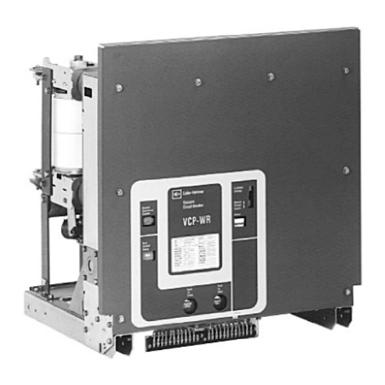
Instructions for the Use, Operation and Maintenance of
The Red Line Types VCP-WR, VCP-WRC, VCP-WRG and VCP-WRGC
Fixed Vacuum Circuit Breaker Elements
I.B. 8295A61H07 Supersedes I.B. 8295A61H06 dated November 2005
Effective February 2007
VCP-WR Series 29
I.B. 8295A61H07
For more information visit:
www.EatonElectrical.com
Advertisement
Table of Contents

Related Manuals for Eaton Cutler-Hammer VCP-WR Series


Summary of Contents for Eaton Cutler-Hammer VCP-WR Series
- Page 1 Instructions for the Use, Operation and Maintenance of The Red Line Types VCP-WR, VCP-WRC, VCP-WRG and VCP-WRGC Fixed Vacuum Circuit Breaker Elements I.B. 8295A61H07 Supersedes I.B. 8295A61H06 dated November 2005 Effective February 2007 VCP-WR Series 29 I.B. 8295A61H07 For more information visit: www.EatonElectrical.com...
- Page 3 Instruction Book Effective: February 2007 Page iii WARNING WARNING THE CIRCUIT BREAKER ELEMENTS DESCRIBED IN THIS BOOK ARE DESIGNED AND TESTED TO IMPROPERLY INSTALLING OR MAINTAINING OPERATE WITHIN THEIR NAMEPLATE RATINGS. THESE PRODUCTS CAN RESULT IN DEATH, OPERATION OUTSIDE OF THESE RATINGS MAY SERIOUS PERSONAL INJURY OR PROPERTY CAUSE THE EQUIPMENT TO FAIL, RESULTING IN DAMAGE.
-
Page 4: Table Of Contents
Instruction Book Page iv Effective: February 2007 TABLE OF CONTENTS Page SECTION 1 INTRODUCTION Type VCP-WR (Red Line Series) Ratings ......................1 Type VCP-WR Outlines and Dimensions ......................3 SECTION 2 SAFE PRACTICES ..........................15 SECTION 3 RECEIVING, HANDLING AND STORAGE ....................16 Receiving ................................16 Handling................................16 Storage ................................16... - Page 5 Instruction Book Effective: February 2007 Page v Page SECTION 6 BREAKER ELEMENT INTERFACING ....................34 6-1 Introduction................................34 6-2 General Guidelines..............................34 6-2.1 Electrical Clearances .......................... 34 6-2.2 Interphase Barriers ..........................34 6-2.3 Front Cover (Faceplate) ........................34 6-2.4 Compartment Interface Verification ....................35 Series 18 Breaker Element Interfaces......................
- Page 6 Instruction Book Page vi Effective: February 2007 FIGURES Figure Title Page Type VCP-WR Series 18 Element Outlines and Dimensions (inches) ............3 Type VCP-WR Series 20 Element Outlines and Dimensions (inches) ............5 Type VCP-WR Series 29 Element Outlines and Dimensions (inches) ............7 Type VCP-WR Series 29 (240/270) Element Outlines and Dimensions (inches) ........10 Front View VCP-WR Series 18........................18 Rear View VCP-WR Series 18 ........................19...
-
Page 7: Section 1 Introduction
Instruction Book Effective: February 2007 Page 1 SECTION 1: INTRODUCTION The purpose of this book is to provide instructions for WARNING unpacking, storage, use, operation and maintenance of Type VCP-WR Vacuum Circuit Breakers. VCP-WR is a vacuum interrupting element designed for value added SATISFACTORY PERFORMANCE OF THESE construction. - Page 8 Instruction Book Page 2 Effective: February 2007 Table 1.2 (ANSI Standards) Type VCP-WRC Extra Capability Vacuum Circuit Breaker 5-27 kV Rated Symmetrical Current Basis Identification Rated voltage Voltage Insulation level Current Capacitor Switching Ratings Mechanical General Endurance Voltage Inter- Maximum Withstand test Short circuit current Transient...
-
Page 9: Type Vcp-Wr Outlines And Dimensions
Instruction Book Effective: February 2007 Page 3 1-2 TYPE VCP-WR OUTLINES AND DIMENSIONS Figure 1-1 VCP-WR Series 18 Element Outlines and Dimensions (inches) I.B. 8295A61H07 For more information visit: www.EatonElectrical.com... - Page 10 Instruction Book Page 4 Effective: February 2007 Figure 1-1 VCP-WR Series 18 Element Outlines and Dimensions (inches) -continued For more information visit: www.EatonElectrical.com I.B. 8295A61H07...
- Page 11 Instruction Book Effective: February 2007 Page 5 Figure 1-2 VCP-WR Series 20 Element Outlines and Dimensions (inches) I.B. 8295A61H07 For more information visit: www.EatonElectrical.com...
- Page 12 Instruction Book Page 6 Effective: February 2007 Figure 1-2 VCP-WR Series 20 Element Outlines and Dimensions (inches) –continued For more information visit: www.EatonElectrical.com I.B. 8295A61H07...
- Page 13 Instruction Book Effective: February 2007 Page 7 Figure 1-3 VCP-WR Series 29 Element Outlines and Dimensions (inches) I.B. 8295A61H07 For more information visit: www.EatonElectrical.com...
- Page 14 Instruction Book Page 8 Effective: February 2007 Figure 1-3 VCP-WR Series 29 Element Outlines and Dimensions (inches) -continued For more information visit: www.EatonElectrical.com I.B. 8295A61H07...
- Page 15 Instruction Book Effective: February 2007 Page 9 Figure 1-3 VCP-WR Series 29 Element Outlines and Dimensions (inches) -continued I.B. 8295A61H07 For more information visit: www.EatonElectrical.com...
- Page 16 Instruction Book Page 10 Effective: February 2007 Figure 1-4 240/270 VCP-WR Series 29 Element Outlines and Dimensions (inches) For more information visit: www.EatonElectrical.com I.B. 8295A61H07...
- Page 17 Instruction Book Effective: February 2007 Page 11 Figure 1-5 240/270 VCP-WR Series 29 Element Outlines and Dimensions (inches) -continued I.B. 8295A61H07 For more information visit: www.EatonElectrical.com...
- Page 18 Instruction Book Page 12 Effective: February 2007 Figure 1-6 240/270 VCP-WR Series 29 Element Outlines and Dimensions (inches) -continued For more information visit: www.EatonElectrical.com I.B. 8295A61H07...
- Page 19 Instruction Book Effective: February 2007 Page 13 Figure 1-7 240/270 VCP-WR and VCP-WRGC Series 29 Element Outlines and Dimensions (inches) -continued I.B. 8295A61H07 For more information visit: www.EatonElectrical.com...
- Page 20 Instruction Book Page 14 Effective: February 2007 Figure 1-8 240/270 VCP-WR and VCP-WRGC Series 29 Element Outlines and Dimensions (inches) -continued For more information visit: www.EatonElectrical.com I.B. 8295A61H07...
-
Page 21: Section 2 Safe Practices
Instruction Book Effective: February 2007 Page 15 SECTION 2: SAFE PRACTICES secondary power are disconnected from the breaker. Failure to do so could result in electrical shock leading Type VCP-WR breakers are equipped with high speed, to death, severe personal injury or property damage. high energy operating mechanisms. -
Page 22: Section 3 Receiving, Handling And Storage
Instruction Book Page 16 Effective: February 2007 FALL CAUSING SEVERE PERSONAL INJURY. SECTION 3: RECEIVING, HANDLING AND ALWAYS PERFORM MAINTENANCE, REPAIR AND STORAGE ADJUSTMENTS ON A WORKBENCH CAPABLE OF SUPPORTING THE BREAKER. Type VCP-WR circuit breakers are subjected to complete factory production tests and inspection Type VCP-WR breaker shipping containers are designed before being packed. -
Page 23: Type Vcp-Wr Breaker Weights
Instruction Book Effective: February 2007 Page 17 cause rusting of metal parts and deterioration of high voltage insulation. A heat level of approximately 400 3-4 TYPE VCP-WR BREAKER WEIGHTS watts for each 100 cubic feet of volume is recommended with the heaters distributed uniformly throughout the T able 3.1 V CP -W R Bre ake r W eights ( pounds ) structure near the floor. -
Page 24: Front View Vcp-Wr Series 18
Instruction Book Page 18 Effective: February 2007 Fi gur e 3 -1 Fron t Vie w VC P -W R S eri es 18 For more information visit: www.EatonElectrical.com I.B. 8295A61H07... -
Page 25: Rear View Vcp-Wr Series 18
Instruction Book Effective: February 2007 Page 19 Fi gur e 3 -2 Rea r Vie w VCP -W R Se ries 1 8 I.B. 8295A61H07 For more information visit: www.EatonElectrical.com... -
Page 26: Front View Vcp-Wr Series 20
Instruction Book Page 20 Effective: February 2007 Fi gur e 3 -3 Fron t Vie w VC P -W R S eri es 20 For more information visit: www.EatonElectrical.com I.B. 8295A61H07... - Page 27 Instruction Book Effective: February 2007 Page 21 Figure 3-4 Front External View of DHP-VR Breaker (7.5 and 15 kV, 500 and 750 MVA Ratings) I.B. 8295A61H07 For more information visit: www.EatonElectrical.com...
-
Page 28: Front View Vcp-Wr Series 29
Instruction Book Page 22 Effective: February 2007 Fi gur e 3 -5 Fron t Vie w VC P -W R S eri es 29 For more information visit: www.EatonElectrical.com I.B. 8295A61H07... -
Page 29: Rear View Vcp-Wr Series 29
Instruction Book Effective: February 2007 Page 23 Fi gur e 3 -6 Rea r Vie w VCP -W R Se ries 2 9 I.B. 8295A61H07 For more information visit: www.EatonElectrical.com... -
Page 30: Typical Vcp-Wr Escutcheon
Instruction Book Page 24 Effective: February 2007 Figure 3-7 Typical VCP-WR Escutcheon For more information visit: www.EatonElectrical.com I.B. 8295A61H07... -
Page 31: Section 4 Inspection And Operation
Instruction Book Effective: February 2007 Page 25 SECTION 4: INSPECTION AND OPERATION 4-3 INTERFACE VERIFICATION It is the customer’s responsibility to insure that all 4-1 INITIAL INSPECTION drawout circuit breakers interface and operate properly in conjunction with their breaker compartments. This Before attempting to use or put a breaker into service, will include but not be limited to verification that examine it for loose or obviously damaged parts. -
Page 32: Section 5 Description And Operation
Instruction Book Page 26 Effective: February 2007 SECTION 5: DESCRIPTION AND OPERATION used have a proven record for reliability, long life and minimal maintenance (Figures 3-2, 3-4 and 3-6). Cutler-Hammer Type VCP-WR breaker elements are The standard primary insulation used on all VCP-WR vacuum type interrupting elements designed to offer breaker elements is high strength, flame retardant glass value added construction. -
Page 33: Typical Vcp-Wr Front Mounted Mechanism
Instruction Book Effective: February 2007 Page 27 Figure 5-1 Typical VCP-WR Front Mounted Mechanism I.B. 8295A61H07 For more information visit: www.EatonElectrical.com... -
Page 34: 5-2.2 Contact Erosion Indicator
Instruction Book Page 28 Effective: February 2007 5-2.2 CONTACT EROSION INDICATOR The purpose of the contact erosion indicator is to monitor any erosion of the vacuum interrupter contacts. Contact erosion is, however, very minimal over time with Cutler-Hammer vacuum interrupters utilizing copper-chrome contact material. -
Page 35: 5-2.3 "T" Cutout Loading Spring Indicator
Instruction Book Effective: February 2007 Page 29 Wipe and Stroke are thus related to each other. As the stroke increases due to the erosion of contacts, the wipe decreases. A great deal of effort has been spent in the design of all Cutler-Hammer vacuum breakers, in order to eliminate the need for field adjustments of wipe or stroke. -
Page 36: 5-3.2 Charging
Instruction Book Page 30 Effective: February 2007 5-3.2 CHARGING Figure 5-6d shows the breaker in the closed position Figure 5-7 is a schematic view of the spring charging after the closing springs have been recharged. Note that parts of the stored energy mechanism. the spring charging rotates the closing cam by one half turn. -
Page 37: Closing Cam And Trip Linkage
Instruction Book Effective: February 2007 Page 31 Fi gur e 5 -6 Clos i ng Ca m an d T rip Link a ge I.B. 8295A61H07 For more information visit: www.EatonElectrical.com... -
Page 38: Charging Schematic
Instruction Book Page 32 Effective: February 2007 Fi gur e 5 -7 ch argi ng sc h em a tic For more information visit: www.EatonElectrical.com I.B. 8295A61H07... -
Page 39: 5-4.1 Timing
Instruction Book Effective: February 2007 Page 33 Note the position switch (PS1) contact in the spring Table 5.1 Breaker Timing release circuit in the scheme. This contact remains made while the breaker is being levered between the TEST and CONNECTED positions for appropriately Event Milliseconds (maximum) retrofitted breakers. -
Page 40: Section 6 Breaker Element Interfacing
Instruction Book Page 34 Effective: February 2007 SECTION 6: BREAKER ELEMENT the appropriate ANSI standard and the specific BIL level INTERFACING of application. The BIL Rating associated with a particular breaker element is clearly indicated on the 6-1 INTRODUCTION breaker’s nameplate located on the front cover. 6-2.2 INTERPHASE BARRIERS WARNING ANSI standards require specific minimum air space... -
Page 41: 6-2.4 Compartment Interface Verification
Instruction Book Effective: February 2007 Page 35 6-2.4 COMPARTMENT INTERFACE VERIFICATION • Review the Series 18 specific control scheme (Figure 6-2) and the outline drawing (Figures 1-1) presented earlier before proceeding. Refer to paragraph 4-3 in this instruction book for details. - Page 42 Instruction Book Page 36 Effective: February 2007 Figure 6-2 Typical VCP-WR “DC” and “AC” Contral Schematics For more information visit: www.EatonElectrical.com I.B. 8295A61H07...
-
Page 43: Series 20 Breaker Element Interfaces
Instruction Book Effective: February 2007 Page 37 Series 18 breaker element (Figure 6-4). An optional 1. The breaker is held mechanically trip free during additional top MOC drive is available in the form of a kit racking. The latch check switch is also held open, (Style 8794C82G01). -
Page 44: 6-4.2 Electrical Interfaces
Instruction Book Page 38 Effective: February 2007 • The appropriately sized and secured primary • Review the details presented in Table 1.1 and connections for fixed or drawout designs. Refer to the Figures 1-2, 3-3, 3-4, 3-7 and 5-1. following specific details entitled “Primary Connections.” •... -
Page 45: Series 29 Breaker Element Interfaces
Instruction Book Effective: February 2007 Page 39 as the auxiliary switch contacts in the breaker. The • Review the details presented in Table 1.1 and Figures MOC switch operator is located on the bottom of the 1-3, 3-5, 3-6, 3-7 and 5-1. Series 20 breaker element (Figure 6-6). -
Page 46: Series 29 Primary Connection
Instruction Book Page 40 Effective: February 2007 drawing (Figure 1-3) for specific details as to exact The functions they are intended to perform are as follows: locations and the amount of travel associated with each 1. The breaker is held mechanically trip free during trip-per. -
Page 47: Section 7 Inspection And Maintenance
Instruction Book Effective: February 2007 Page 41 • DO NOT STAND LESS THAN ONE METER AWAY SECTION 7: INSPECTION AND FROM THE BREAKER WHEN TESTING FOR MAINTENANCE VACUUM INTEGRITY. 7-1 INTRODUCTION FAILURE TO FOLLOW ANY OF THESE INSTRUCTIONS MAY CAUSE DEATH, SERIOUS BODILY INJURY, OR PROPERTY DAMAGE. -
Page 48: Inspection And Maintenance Procedures
Instruction Book Page 42 Effective: February 2007 7-3 INSPECTION AND MAINTENANCE PROCEDURES No./Section Inspection Item Criteria Inspection Method Corrective Action 1. Insulation Drive Insulator No dirt Visual Check Clean with lint-free cloth. No cracking Visual Check Replace cracked unit Molded Pole Unit Support Withstand Clean and retest or replace Hipot Tester... -
Page 49: Vacuum Interrupter Integrity Test
Instruction Book Effective: February 2007 Page 43 SECTION 7: INSPECTION AND CAUTION MAINTENANCE 7-1 INTRODUCTION APPLYING ABNORMALLY HIGH VOLTAGE ACROSS A PAIR OF CONTACTS IN VACUUM MAY PRODUCE X-RADIATION. THE RADIATION MAY INCREASE WARNING WITH THE INCREASE IN VOLTAGE AND/OR DECREASE IN CONTACT SPACING. -
Page 50: Contact Erosion And Wipe
Instruction Book Page 44 Effective: February 2007 Figure 7-2 Vacuum Interrupter Showing Contact Erosion Figure 7-3 Vacuum Interrupter Showing Contact Erosion Indicator with Breaker Open (Shown here for Clarity Indicator with Breaker Closed (Indicators are Checked Purposes Only). Only When Breaker is Closed). In this case the equipment must be capable of delivering ever, during high current interruptions there may be a 5 milliamperes for one minute to avoid ambiguity due to... -
Page 51: Insulation
Instruction Book Effective: February 2007 Page 45 Conduct the test as follows: Close the breaker. Connect the high potential lead of the test machine to one of the poles of the breaker. Connect the remaining poles and breaker frame to ground. Start the machine with output potential at zero and increase to the test voltage. -
Page 52: Wipe Indication Procedure
Instruction Book Page 46 Effective: February 2007 Figure 7-5 Wipe Indication Procedure (Performed Only with Breaker Closed) For more information visit: www.EatonElectrical.com I.B. 8295A61H07... -
Page 53: Troubleshooting Chart
Instruction Book Effective: February 2007 Page 47 7-11 TROUBLESHOOTING CHART S YM P TOM I NSPE CTIO N ARE A PROBABLE DEFECTS Fails To Close Closing Springs not charged Control Power (fuse blown • Control Circuit • or switch off) Secondary Disconnects •... - Page 54 Instruction Book Page 48 Effective: February 2007 S YM P TOM I NSPE CTIO N ARE A PROBABLE DEFECTS Fails To Close Closing Spring charged but • No Closing Sound • Control Power • breaker does not close (Close Coil does not pick up) (Fuse blown or switch off) •...
- Page 55 Instruction Book Effective: February 2007 Page 49 S YM P TOM I NSPE CTIO N ARE A PROBABLE DEFECTS Fails To Close • Control Power (Fuse • No trip sound Control circuit • blown or switch off) • Secondary Disconnect •...
-
Page 56: Section 8 Renewal Parts
Instruction Book Page 50 Effective: February 2007 SECTION 8: RENEWAL PARTS 8-2 ORDERING INSTRUCTIONS 8-1 GENERAL a. Always specify the breaker rating informotion and shop order number. In order to minimize production downtime, it is recommended that an adequate quantity of spare parts b. - Page 57 Instruction Book Effective: February 2007 Page 51 Table 8.1 Recommended VCP-WR Spare Parts (Continued) Style Number Style Number Description Type, Cont, Current,C&L VCP-29WR VCP-29WRSE Interrupter Assembly 3A73901H01 50/250, 1200A - 58kA (4”) (4”SC) 3A73901H21 3A73902H01 50/250, 2000A - 58kA (5”) 3A73902H21 (5”SC) 3A73903H01...
- Page 58 Instruction Book Page 52 Effective: February 2007 Style Number Style Number Description Type, Cont, Current, C&L VCP-29WR VCP-29WRSE 3A73907H02 3A73907H01 75/500, 1200A - 66kA 3A73908H01 3A73908H02 75/500, 2000A - 66kA 3A73909H01 3A73909H02 75/500, 3000A - 66kA 3A73910H01 3A73910H02 150/500, 1200A - 37kA (4”) 3A73910H21 3A73910H22 (3”SC)
- Page 59 Instruction Book Effective: February 2007 Page 53 Style Number Style Number Description Type, Cont, Current, C&L VCP-29WR VCP-29WRSE 3A73913H02 3A73913H01 150/750, 1200A - 58kA 3A73914H01 3A73914H02 150/750, 2000A - 58kA 3A73915H01 3A73915H02 150/750, 3000A - 58kA 3A73916H01 3A73916H02 150/1000, 1200A - 77kA 3A73917H02 3A73917H01 150/1000, 2000A - 77kA...
- Page 60 Instruction Book Page 54 Effective: February 2007 Table 8.1 Recommended VCP-WR Spare Parts (Continued) Style Number Style Number Description Type, Cont, Current, C&L VCP-29WR VCP-29WRSE 150/63, 1200A - 101kA 3A73916H31 150/63, 2000A - 58kA 3A73917H31 150/63, 3000A - 58kA 3A73918H31 270/25, 32,40,1200A 8297A37G01 270/25, 32,40,2000A...
- Page 61 Instruction Book Effective: February 2007 Page 55 Table 8.1 Recommended VCP-WR Spare Parts (Continued) Style Number Description Type, cont, current, C&L VCP-18WR 50/250, 1200A - 58kA 3A73923H01 50/250, 1200A - 78kA 3A73932H01 50/250, 2000A - 58kA 3A73924H01 50/350, 2000A - 78kA 3A73933H01 75/500, 1200A - 66kA 3A73925H01...
- Page 62 Instruction Book Page 56 Effective: February 2007 Style Number Description Type, cont, current, C&L VCP-18WR 150/500, 2000A - 37kA 3A73929H01 150/750, 1200A - 58kA 3A73930H01 150/750, 2000A - 58kA 3A73931H01 Style Number Style Number Description Type, cont, current, C&L VCP-29WR VCP-29WRSE 3A73913H01 Phase Barriers...
- Page 63 Instruction Book Effective: February 2007 Page 57 Style Number Style Number Description Type, cont, current, C&L VCP-29WR VCP-29WRSE Push Rod Assemblies 692C799G01 Up to 15kV BLUE SPRINGS 692C799G02 Up to 15kV RED SPRINGS 692C650G01 692C650G02 Up to 15kV WHITE SPRINGS 692C651G01 692C651G02 Up to 15kV...
- Page 64 Instruction Book Page 58 Effective: February 2007 Style Number Style Number Description VCP-29WR VCP-29WRSE Lower Support Up to 15kV 5697B19H01 686C575H01 350, 1000 MVA 1200, 2000A 27kV 1C94707H01 Shock absorber 350,1000MVA 5677B26H01 5677B26H01 1200,2000A 63kA 27kV Style Number Description VCP-20WR Phase Barriers 690C846H01 Up to 5kV...
- Page 65 Instruction Book Effective: February 2007 Page 59 Style Number Description VCP-20WR Tie bars 690C818H01 Up to 5kV Style Number Description VCP-20WR Phase Barriers Up to 5kV 5677B34H01 (except) 50/350,1200A/2000A 5677B36H01 5677B26H01 Shock Absorber Style Number Description VCP-29WR VCP-29WRSE VCP-20WR VCP-18WR Charging Motor 699B196G06 699B196G06...
- Page 66 Instruction Book Page 60 Effective: February 2007 Style Number Description VCP-29WR VCP-29WRSE VCP-20WR VCP-18WR Spring Release Coils 3759A76G11 3759A76G11 3759A76G11 3759A76G11 48DC 3759A76G12 3759A76G12 3759A76G12 3759A76G12 125VDC/120VAC 3759A76G13 3759A76G13 3759A76G13 3759A76G13 250VDC/240VAC Rectifier 3759A79G02 3759A79G02 3759A79G02 3759A79G02 120/240VAC Anti Pump (Y) Relay 8237A27H03 8237A27H03 8237A27H03...
- Page 67 Instruction Book Effective: February 2007 Page 61 Table 8.1 Recommended VCP-WR Spare Parts (Continued) Style Number Description VCP-29WR VCP-29WRSE VCP-20WR VCP-18WR Motor Cutoff Switch 699B199G04 699B199G04 699B199G04 Motor Cutoff Switch 5677B02G11 Latch Check Switch 699B147G01 699B147G01 699B147G01 699B147G01 Position Switch 1 699B147H01 699B147H01 699B147H01...
- Page 68 Instruction Book Page 62 Effective: February 2007 Table 8.1 Recommended VCP-WR Spare Parts (Continued) Style Number Description VCP-29WR VCP-29WRSE VCP-20WR VCP-18WR Trip Latch 699B040G03 699B040G03 699B040G03 699B040G03 (Hatchet) 8295A45G01 Labels Kit 8295A45G01 8295A45G01 8295A45G01 VCP-WR Field Style Number Installation Kit VCP-29WR VCP-20WR VCP-18WR...
- Page 69 Instruction Book Effective: February 2007 Page 63 Table 8.1 Recommended VCP-WR Spare Parts (Continued) Description Style Number Type, Cont, Current, C&L VCP-WRG 50/63 WRG,1200A 8297A29H33 50/63 WRG,2000A 8297A30H33 50/63 WRG,3000A 8297A31H33 8297A29H35 150/63 WRG, 1200A 8297A30H35 150/63 WRG, 2000A 8297A31H35 150/63 WRG, 3000A 150/ WRG 50 C, 2000A 8297A37G09...
- Page 70 Instruction Book Page 64 Effective: February 2007 For more information visit: www.EatonElectrical.com I.B. 8295A61H07...
- Page 71 Effective: F ebr uary 2007 Fixed Vacuum Circuit Breaker Elements Corporation Cutler-Hammer business unit 1000 Cherrington Parkway Moon Township, PA 15108-4312 tel: 1-800-525-2000 www.cutler-hammer.eaton.com © 2005 Eaton Corporation All Rights Reserved Printed in USA Publication No. IB8295A61H07 (ISI) February 2007...
Need help?
Do you have a question about the Cutler-Hammer VCP-WR Series and is the answer not in the manual?
Questions and answers