Sign In
Upload
Manuals
Brands
Eaton Manuals
Circuit breakers
75 VCP-WR 500
Eaton 75 VCP-WR 500 Manuals
Manuals and User Guides for Eaton 75 VCP-WR 500. We have
1
Eaton 75 VCP-WR 500 manual available for free PDF download: Instructions For The Use, Operation And Maintenance
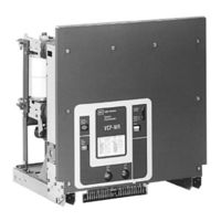
Eaton 75 VCP-WR 500 Instructions For The Use, Operation And Maintenance (63 pages)
Red Line Vacuum Circuit Breaker Elements
Brand:
Eaton
| Category:
Circuit breakers
| Size: 1.52 MB
Table of Contents
Table of Contents
4
Introduction
7
Type VCP-WR (Red Line Series) Ratings
7
Type VCP-WR Outlines and Dimensions
8
Safe Practices
15
Receiving, Handling and Storage
16
Receiving
16
Handling
16
Storage
16
Type VCP-WR Breaker Weights
17
Typical VCP-WR Escutcheon
24
Inspection and Operation
25
Initial Inspection
25
Manual Operation Check
25
Interface Verification
25
Description and Operation
26
Circuit Breaker Elements
26
Interrupter Assembly
26
5-2.1 Vacuum Interrupter
26
Typical VCP-WR Front Mounted Mechanism
27
5-2.2 Contact Erosion Indicator
28
Type VCP-WR Series 20 Interrupter Assemblies
28
Type VCP-WR Series 18 Interrupter Assemblies
28
Type VCP-WR Series 29 Interrupter Assemblies
28
5-2.3 "T" Cutout Loading Spring Indicator
29
5-2.4 Contact Wipe and Stroke
29
Stored Energy Mechanism
29
5-3.1 Operation of Stored Energy Mechanism
29
Typical Cutler-Hammer Vacuum Interrupter Shown Attached to Non-Sliding Current Transfer System
29
5-3.2 Charging
30
5-3.3 Closing Operation
30
5-3.4 Tripping Operation
30
5-3.5 Trip Free Operation
30
Control Schemes
30
Closing Cam and Trip Linkage
31
Charging Schematic
32
5-4.1 Timing
33
5-4.2 Terminal Blocks
33
Operations Counter
33
Breaker Element Interfacing
34
Introduction
34
General Guidelines
34
6-2.1 Electrical Clearances
34
6-2.2 Interphase Barriers
34
6-2.3 Front Cover (Faceplate)
34
6-2.4 Compartment Interface Verification
35
Series 18 Breaker Element Interfaces
35
6-3.1 Initial Interfacing Steps
35
6-3.2 Electrical Interfaces
35
6-3.3 Mechanical Interfaces
35
Typical VCP-WR Front Cover, Nameplate and Operational Indicators
35
Typical VCP-WR "DC" and "AC" Control Schematics
36
Series 20 Breaker Element Interfaces
37
6-4.1 Initial Interfacing Steps
37
Series 18 Primary Connection
37
Series 18 Showing Bottom Accessed Interlocks and MOC Operator
37
6-4.2 Electrical Interfaces
38
6-4.3 Mechanical Interfaces
38
Series 20 Primary Connection
38
Series 29 Breaker Element Interfaces
39
6-5.1 Initial Interfacing Steps
39
6-5.2 Electrical Interfaces
39
6-5.3 Mechanical Interfaces
39
Series 20 Showing Bottom Accessed Interlocks and MOC Operator
39
Series 29 Primary Connection
40
Series 29 Showing Bottom Accessed Interlocks and MOC Operator
40
Inspection and Maintenance
41
Introduction
41
Frequency of Inspection
41
Lubrication Points
41
Inspection and Maintenance Procedures
42
Vacuum Interrupter Integrity Test
43
Contact Erosion and Wipe
43
Insulation
44
Insulation Integrity Check
44
Vacuum Interrupter Showing Contact Erosion Indicator with Breaker Open
44
Vacuum Interrupter Showing Contact Erosion Indicator with Breaker Closed
44
Primary Circuit Resistance Check
45
Mechanism Check
45
Lubrication
45
Typical "T" Contact Wipe Indicator
45
Wipe Indication Procedure
46
Troubleshooting Chart
47
Renewal Parts
50
General
50
Ordering Instructions
50
Advertisement
Advertisement
Related Products
Eaton 75VCP-W 40
Eaton 75VCP-W 50
Eaton Cutler-Hammer 75 VCP-WR50C
Eaton 75 VCP-TL16
Eaton 75 VCP-TRL16
Eaton 75 VCP-TL20
Eaton 75 VCP-TRL20
Eaton 75 VCP-TL25
Eaton 75 VCP-TRL25
Eaton 75DVP-VR
Eaton Categories
UPS
Circuit breakers
Industrial Equipment
Switch
Industrial Electrical
More Eaton Manuals
Login
Sign In
OR
Sign in with Facebook
Sign in with Google
Upload manual
Upload from disk
Upload from URL