Eaton Cutler-Hammer Digitrip 1150 Instructions Manual
Hide thumbs
Also See for Cutler-Hammer Digitrip 1150:
- Instruction manual (10 pages) ,
- Instructions manual (84 pages)
Table of Contents
Advertisement
I.L. 70C1036H01
Instructions for Digitrip Models 1150 and 1150i
Trip Units for use only in Cutler-Hammer Magnum
and Magnum DS Circuit Breakers
Table of Contents
1.0 General Description of Digitrip Units ....................... 5
1.1 Protection ............................................................... 5
1.2 Mode of Trip and Status Information ....................... 5
1.3.1 Installation of the Trip Unit ............................ 5
1.3.2 Rating Plug Installation ................................. 6
1.3.3 Trip Unit/Rating Plug Removal ..................... 7
1.4 Wiring ..................................................................... 7
1.6 DT 1150 Power/Relay Module ................................ 7
1.6.1 Auxiliary Power ............................................ 7
1.6.2 Alarm Contacts ............................................ 7
1.7 Standards ............................................................... 8
Magnum Circuit Breakers ....................................... 8
2.1 General .................................................................. 8
2.2 Low-Energy Trip Actuator ....................................... 9
2.3 Ground Fault Protection ......................................... 9
2.3.1 General ........................................................ 9
2.3.2 Residual Sensing ....................................... 10
2.3.3 Source Ground Sensing ............................. 10
2.3.4 Zero Sequence Sensing ............................. 10
2.3.5 Multiple Source/Multiple Ground ................ 10
2.3.6 Ground Fault Settings ................................ 10
equal to 3200A) .................................................... 11
than 3200A) .......................................................... 11
3.0 Principles of Operation ......................................... 11
3.1 General ................................................................ 11
3.2 Trip and Operation Indicators ............................... 11
3.2.1 Status LED ................................................. 12
3.2.2 Alarm LED ................................................. 12
3.2.3 Trip LED ..................................................... 12
3.3 Making Current Release ....................................... 12
3.4 Zone Interlocking .................................................. 12
3.5 PT Module ............................................................ 17
4.0 Programming/View Digitrip 1150 ........................... 17
4.1 Main Menu ............................................................ 17
4.1.0 Power Up Sequence .................................. 17
4.1.1 Pushbutton Definition ................................. 17
4.1.2 Blink mode ................................................. 20
4.1.3 Programming/Viewing Screens .................. 20
4.2 Program Settings PGM SET ................................. 21
Time Settings ....................................................... 21
4.2.2 AMP UNBALANCE, PHASE LOSS ............ 24
4.2.3 INCOM ....................................................... 24
Effective 8/18/99
Courtesy of NationalSwitchgear.com
4.2.4 Aux RELAYS .............................................. 25
4.2.5 ALARMS .................................................... 26
4.2.6 ACCessory BUS (Relays) .......................... 26
4.2.7 TRIPLINK ................................................... 26
4.2.8 Setting TIME .............................................. 27
4.2.9 Selecting DISPLAYS .................................. 27
4.2.10 GENERAL settings .................................... 27
4.3 View Settings (VIEW SET) ................................... 27
4.3.1 Firmware Menu .......................................... 27
4.4 METER ................................................................. 27
4.5 HARMONIC Menu ................................................ 28
4.6 EventLOG ............................................................. 28
4.7 Power and Energy Parameters ............................. 28
4.8 Power Quality ....................................................... 29
4.8.1 Power Factor, THD and Crest Factor ......... 29
4.8.2 Alarms ........................................................ 29
4.9 WAVEFORM CAPTURE feature .......................... 29
4.9.1 Six Cycle Waveform Capture on trip .......... 29
5.0 Test Procedure ..................................................... 29
5.1 General ................................................................ 29
5.2 When to Test ........................................................ 30
5.3.1 Self Testing ................................................ 30
5.3.2 Functional Field Testing ............................. 30
5.4.1 Code Requirements ................................... 30
5.4.2 Standard Requirements ............................. 30
5.4.3 General Test Instructions ........................... 30
6.0 Battery .................................................................. 31
6.1 General ................................................................ 31
6.2 Battery Check ....................................................... 31
6.3 Battery Installation and Removal .......................... 32
(Sensor Ratings and Rating Plugs) ....................... 32
8.0 Record Keeping .................................................... 33
9.0 References ........................................................... 33
9.1 Magnum and Magnum DS Circuit Breakers ......... 33
9.2 Time-Current Curves ............................................ 33
Appendix A Zone Interlocking Example ........................ 38
Appendix B Troubleshooting Guide .............................. 39
Connection Diagram ............................................. 41
Appendix D Display Menu Diagrams ...................... 42- 63
Appendix E Display Abbreviations .......................... 65- 66
Appendix F Auxiliary Relays ......................................... 67
Output Modules .................................................... 68
I.L. 70C1036H01
Page 1
Advertisement
Table of Contents

Related Manuals for Eaton Cutler-Hammer Digitrip 1150


Summary of Contents for Eaton Cutler-Hammer Digitrip 1150
-
Page 1: Table Of Contents
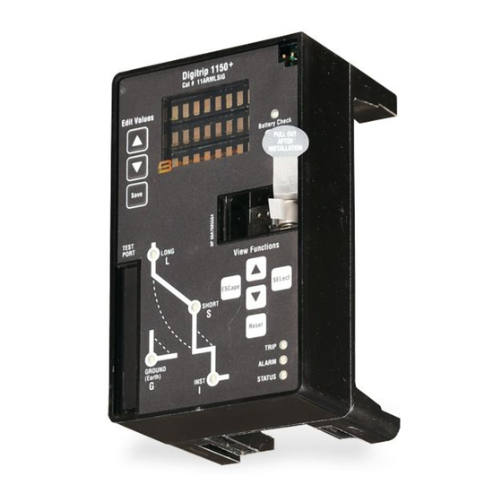
I.L. 70C1036H01 I.L. 70C1036H01 Page 1 Instructions for Digitrip Models 1150 and 1150i Trip Units for use only in Cutler-Hammer Magnum and Magnum DS Circuit Breakers Table of Contents 1.0 General Description of Digitrip Units ....... 5 4.2.4 Aux RELAYS ..........25 1.1 Protection ............... - Page 2 I.L. 70C1036H01 Page 2 Figure 1.1 Digitrip 1150 Catalog # 11LSIG Trip Unit with Rating Plug WARNING WARNING DO NOT ATTEMPT TO INSTALL OR PERFORM OBSERVE ALL RECOMMENDATIONS, NOTES, MAINTENANCE ON EQUIPMENT WHILE IT IS CAUTIONS, AND WARNINGS RELATING TO THE ENERGIZED.
- Page 3 I.L. 70C1036H01 Page 3 Table 1.1a Protection Functions for Digitrip 1150/1150i Trip Units T rip U n it T yp e D ig itrip 1150 D ig itrip 1150i A m pere R ange 200A -5000A 200A -6300A R M S S en sing Y es Y es P ro tectio n an d C o o rd in atio n...
- Page 4 I.L. 70C1036H01 Page 4 Table 1.1b Metering Data for Digitrip 1150/1150i Trip Units Current Metering Units Tolerance Notes IA, IB, IC, IN, IG Amperes ± 1% FS Real time data, FS = In rating IA, IB, IC (AVG) Amperes 5 MINUTE AVERAGE IN, IG (AVG) Amperes 5 MINUTE AVERAGE...
-
Page 5: General Description Of Digitrip Units
I.L. 70C1036H01 Page 5 If you have any questions or need further information or mounted in the circuit breaker. The types of protection instructions, please contact your local representative or available for each model are shown in Table 1.1. the Customer Support Center at 1-800-356-1234. The Digitrip 1150 family of trip units provides five phase 1.0 GENERAL DESCRIPTION OF DIGITRIP TRIP UNITS and two ground (time-current) curve-shaping adjust-... -
Page 6: Rating Plug Installation
I.L. 70C1036H01 Page 6 Figure 1.2 Installation of the Digitrip Unit into a Magnum Breaker (Side View) 1.3.2 Rating Plug Installation CAUTION WARNING IF A RATING PLUG IS NOT INSTALLED IN THE TRIP UNIT, THE UNIT WILL INITIATE A TRIP WHEN IT IS DO NOT ENERGIZE THE MAGNUM BREAKER WITH ENERGIZED. -
Page 7: Trip Unit/Rating Plug Removal
I.L. 70C1036H01 Page 7 To remove the trip unit from the circuit breaker, deflect the top and bottom spring clips to release the unit from the steel mounting plate. Pull the unit to disengage the trip unit’s printed circuit board connectors J0 & I1 from the circuit breaker (see Figure 1.2 and Appendix C). -
Page 8: Standards
I.L. 70C1036H01 Page 8 1.6.2.3 Block Close Relay Also in this module is a relay that can block the remote closing of a circuit breaker after a trip condition. This Block function is enabled by programming the Aux Relay B. See Appendix D-15. 1.7 Standards The Digitrip 1150 Trip Units are listed by the Underwriters Laboratories, Inc. -
Page 9: Low-Energy Trip Actuator
I.L. 70C1036H01 Page 9 When the functional protection settings are exceeded, the located under the black molded platform on which the Digitrip unit supplies a trip signal to the Trip Actuator. As a Digitrip unit is supported. The Trip Actuator contains a result, all tripping operations initiated by the protection permanent magnet assembly, moving and stationary core functions of the Digitrip Trip Unit are performed by its... -
Page 10: Residual Sensing
I.L. 70C1036H01 Page 10 be considered along with the manner and location in TESTS TO COMPLY WITH NEC REQUIREMENTS which the circuit breaker is applied to the system. These UNDER ARTICLE 230-95(C). elements are discussed in Sections 2.3.3 through 2.3.6. 2.3.3 Source Ground Sensing The Digitrip 1150 family uses three modes of sensing to Depending upon the installation requirements, alternate... -
Page 11: Current Sensors (Magnum Frames Less Than Or Equal To 3200A)
I.L. 70C1036H01 Page 11 2.4 Current Sensors (Magnum Frames less than or equal to chip has a built-in over-temperature protection feature, 3200A) factory set to trip the breaker if the chip temperature is excessive. If over-temperature is the reason for the trip The three (3-pole) or four (4-pole) primary current sen- the red Long Delay Time LED will flash and the OVER sors are installed internally in the circuit breaker on the... -
Page 12: Status Led
I.L. 70C1036H01 Page 12 3.2.1 Status LED 3.4 Zone Interlocking This green LED will indicate the operational status of the µ CAUTION protection S RE A chip of the trip unit. If no external power is present and the load current through the circuit breaker exceeds approximately 12 percent (3 phase IF ZONE INTERLOCKING IS NOT TO BE USED (I.E., power) of the current sensor rating, the LED will flash on... - Page 13 I.L. 70C1036H01 Page 13 S ource B lack Trip A ctua tor D ig itrip w ith G F 10:1 R /1 B -7 B -6 B -5 B -4 R /1 10:1 A U X . C T Loa d N otes: In this sch em e, all brea ker seconda ry currents (at the 100 m A level) are sum m ed together at the PC boa rd don ut tra nsform er to sense ground fault via elem ent R 5 .
- Page 14 I.L. 70C1036H01 Page 14 Figure 2.4 Digitrip Neutral Sensor Types Th is w ill defeat all ground fault protection in application fo r 4 pole b reaker. Figure 2.5 4-Pole-3200A Frame Using Residual Ground Fault (Earth-Fault) Sensing Effective 8/18/99 Courtesy of NationalSwitchgear.com...
- Page 15 I.L. 70C1036H01 Page 15 11 50 Figure 2.6 Source Ground Fault Sensing Scheme for 3200A Frame 1150 If th e b re aker is rem oved from cell (B -6 , B -7), jum per disconne cted, R esid ual Groun d setting w ill a pply. Tw o sta ndard IA secondary sensors w ith prim ary in series and seconda ries p aralle l m ay be used.
- Page 16 I.L. 70C1036H01 Page 16 Figure 2.8 Zero Sequence Sensing Scheme for 3200A Frame I /2 I /2 I /2 I /2 i /2 i /2 i /2 Internal Digitrip S ensor i /2 i /2 N eutral S ensors W ired in a Loop C on figuration G round Fault Notes:...
-
Page 17: Module
I.L. 70C1036H01 Page 17 3.5 PT Module 4.0 PROGRAMMING/VIEWING DIGITRIP 1150 via FRONT PANEL The PT Module is internally wired in the breaker to the 4.1 Main Menu line side breaker terminals. It provides signal data to 4.1.0 Power Up Sequence calculate voltage, power, energy and related data. - Page 18 (L ine/U ppe r) P O W E R /R E LAY Trip M od ule A ctu a tor M a king C urrent A u x R elease C ircuitry F E T S w itch (S ee S e ctio n 3.3 ) Trip C au se of S tatus...
- Page 19 I.L. 70C1036H01 Page 19 Figure 3.2 Digitrip 1150 LSI Figure 3.3 Digitrip 1150 LSIA Figure 3.4 Digitrip 1150i IEC Figure 3.5 Digitrip 1150i IEC-EF Effective 8/18/99 Courtesy of NationalSwitchgear.com...
-
Page 20: Blink Mode
I.L. 70C1036H01 Page 20 SELect - The SELect pushbutton selects the submenu for All screens are viewable depending on the programmed the blinking selection located in the middle of the display. settings and/or Digitrip 1150 model. In particular, the METER submenu may be programmed to include any- where from one to 22 viewable screens when METER is ESCape - The ESCape pushbutton brings the user up to selected, based on the settings chosen in the PGM... -
Page 21: Program Settings Pgm Set
I.L. 70C1036H01 Page 21 4.1.4.2 Alarm Events All Digitrip 1150 and Digitrip 1150i offer the LSI(G) as the standard factory default. The five segment straight line curve of LONG PU and Time, SHORT PU and Time, and Alarms are tracked in real time and a Reset pushbutton INSTantaneous PU are depicted on the nameplate of the may momentarily clear the alarm but the alarm will product. - Page 22 I.L. 70C1036H01 Page 22 time the overload condition is repeated, the LTM causes the breaker to trip in a progressively shorter time. When the load current returns to normal, the LTM begins to reset; after about 10 minutes it will have reset fully, so the .4, .45, .5, .55, .6, .65 next Long Delay trip time will again correspond to the .7, .75, .8, .85, .9, .95, 1.0...
- Page 23 I.L. 70C1036H01 Page 23 Available S ettings Setting Inst. 2, 2.5. 3, ... x n I Short Delay 9, 9.5, 10...O FF Tim e .4 S ec. In M ultiples of R ating P lug A m peres ( n) I M 1 va lu e is sp ecified on rating plug.
-
Page 24: Amp Unbalance, Phase Loss
I.L. 70C1036H01 Page 24 4.2.2.2 Phase Loss The phase loss trip function can be selected in the Program Settings - Program Curve Menu (see Appendix Gnd. Fault D-12). It is set to OFF initially as a factory default. By Tim e selecting a Time Delay of 1 to 30 seconds, SAVING will .3 Sec. - Page 25 I.L. 70C1036H01 Page 25 Typical IB M C om patible C om puter Assem blie s Breaker Electronic Interface M o nito r M o nito r (AE M 2) (BIM ) Se e Vie w A Tw iste d P air. N o.
-
Page 26: Aux Relays
I.L. 70C1036H01 Page 26 Figure 4.10 Triplink Transfer 4.2.4 Aux ReLaY 4.2.6 ACCessory BUS (RELAYS) The programmable Auxiliary Relays in the Digitrip 1150 Available addresses 1 through 4 each have four program- consist of Relay A (Alarming), Relay B (Blocking), and mable relay functions (RLY FUNC) also numbered 1 Relay C (Latching). -
Page 27: Setting Time
I.L. 70C1036H01 Page 27 All INCOM settings including INCOM ADDRESS is 4.2.8 Setting TIME transferred via TripLink. A INCOM network does require In the Digitrip 1150, dates are displayed in DD-MmmYY a unique address so the address may later have to be format (for example, 12-Mar98) and time is displayed in changed. -
Page 28: Firmware Menu
I.L. 70C1036H01 Page 28 4.3.1 Firmware Menu Local operation on the Digitrip to observe this data is done using the View Down pushbutton on the front panel The Firmware menu enables the user to view the version of the Digitrip. and revision of the trip unit firmware. -
Page 29: Power Quality
I.L. 70C1036H01 Page 29 Demand Max kW and Demand Max kVA are peak values on the 24 character display as well as illuminating the that have been encountered since the last Reset of these yellow LED and communicating to a host computer. parameters. -
Page 30: Test Procedure
I.L. 70C1036H01 Page 30 5.0 TEST PROCEDURES 5.3.1 Self Testing The Digitrip 1150 provides means via the TEST selection 5.1 General in the main menu to conduct PHase or GrouND testing in either a Trip or Nontrip mode. See Appendix D-20 for WARNING pushbutton sequence to conduct the testing. -
Page 31: Code Requirements
I.L. 70C1036H01 Page 31 5.4 Performance Testing for Ground Fault Trip Units This should cause the breaker to trip in less than 1 second and operate the alarm indicator, if one is supplied. 5.4.1 Code Requirements Reset the breaker and the alarm indicator. Repeat the test on the other two phases (see Figure 5.1). -
Page 32: Battery
I.L. 70C1036H01 Page 32 cell. When inserting the new cell, pay special attention to CAUTION ensure that the proper polarity is observed. The main body of the battery is the positive (+) side. RESTORE ALL TEMPORARY CONNECTIONS MADE FOR THE PURPOSE OF CONDUCTING TESTS TO PROPER OPERATING CONDITIONS BEFORE RE- TURNING THE BREAKER TO SERVICE. -
Page 33: Frame Ratings (Sensor Ratings And Rating Plugs)
I.L. 70C1036H01 Page 33 7.0 FRAME RATINGS (SENSOR RATINGS AND RATING PLUGS) 8.0 RECORD KEEPING The frame rating of a circuit breaker is the maximum Use the forms shown in Figures 8.1 and 8.2 for record RMS current it can continuously carry. The maximum keeping. - Page 34 I.L. 70C1036H01 Page 34 DIGITRIP TRIP FUNCTION SETTINGS Circuit No./Address Breaker Shop Order Reference PER UNIT MULTIPLIERS I r Continuous Ampere Rating Rating Plug Amperes ( I n) = LDS x I n Ampere Trip Per Unit Equivalent Function Setting Multi Setting Time Delay...
- Page 35 I.L. 70C1036H01 Page 35 D IG IT R IP A U T O M A T IC T R IP O P E R A T IO N R E C O R D C irc u it B re a k e r S h o p O rd e r R e fe re n c e N o ./A d d re s s T rip F u n c tio n S e ttin g s R e fe re n c e...
- Page 36 I.L. 70C1036H01 Page 36 GROUND FAULT TEST RECORD FORM Ground Fault Test Record should be retained by those in charge of the building's electrical installation in order to be available to the authority having jurisdiction. Test Date Circuit Breaker Results Tested by Number Figure 8.3 Typical Performance Test Record Form...
-
Page 37: Appendix A Zone Interlocking Example
I.L. 70C1036H01 Page 37 a restraint signal to the feeder trip unit; the feeder will NOTICE send a restraint interlocking signal to Z1. Main and feeder trip units will also begin to time out and, THE PROVISION FOR ZONE INTERLOCKING IS in the event that the branch breaker does not clear the STANDARD ON MAGNUM CIRCUIT BREAKERS WITH fault, the feeder breaker will clear the fault in 0.3 seconds... - Page 38 I.L. 70C1036H01 Page 38 - B 7 C ontact - B 9 C o nta ct - B 8 C o nta ct Figure A.1 Typical Zone Interlocking Figure A.2 Typical Zone Interlocking Connections with Two Main Breakers (M1, M2) and a Tie Breaker (T) Effective 8/18/99 Courtesy of NationalSwitchgear.com...
-
Page 39: Appendix B Troubleshooting Guide
I.L. 70C1036H01 Page 39 Appendix B Troubleshooting Guide Symptom Probable Cause Possible Solution(s) Comments LED display is not energized. No auxiliary power input. Wrong auxiliary power Check voltage input terminals Refer to Section 1.6.1. voltage. A14-A15. As soon as current starts to Rating plug is not installed or Install rating plug and/or flow through the breaker, it... - Page 40 I.L. 70C1036H01 Page 40 Symptom Probable Cause Possible Solution(s) Comments EEROM Non fatal memory error Note settings via view settings If alarm reappear after trying screen. Then enter Program the possible solution. Replace ALERT Settings and SAVE current trip unit at first opportunity. curve.
-
Page 41: Appendix C Typical Breaker Master Connection Diagram
I.L. 70C1036H01 Page 41 Appendix C Typical Breaker Master Connection Diagram Effective 8/18/99 Courtesy of NationalSwitchgear.com... -
Page 42: Appendix D Display Menu Diagrams
I.L. 70C1036H01 Page 42 Appendix D Display Menu Diagrams Appendix D Page D-1 Startup Sequence CHANGE S E L E S C FACTORY SETUP? CUTLER FACTORY Program Factory Settings Current Curve HAMMER SETTINGS Page D-22 (Page D-12) DT 1150 IN USE If any current curve setting (shown on pages D-12 and CUTLER CUSTOMER... - Page 43 I.L. 70C1036H01 Page 43 Appendix D Page D-3 (Continued from D-1) M e t e r M e n u Individual screens are only displayed if their Display Setting is set to "ON". If "AUTO" is set in IA XXXXX Display Settings IA XXXXX IA IB IC...
- Page 44 I.L. 70C1036H01 Page 44 Appendix D Page D-3 (Continued from D-1) Event Menu When a trip event occurs, data from the appropriate Meter Menu screens is captured and then logged for that event. The event numbering scheme (if a trip) is a first-in, first-out type, with the most recent event always being Event #1.
- Page 45 I.L. 70C1036H01 Page 45 Appendix D Page D-4 (Continued from D-3) Possible Events Note: "Meter screens" refer to those on D-2 Alarm screens will be real-time Data logged and shown messages for each event. LONG OVER NEUTRAL 1st & 2nd 1st &...
- Page 46 I.L. 70C1036H01 Page 46 Appendix D Page D-5 (Continued from D-1) View Settings M e n u TIME View Current CURRENT Curve ESC / SEL (Page D-6) GENERAL V I E W CURRENT SLIDING WAVEFORM GENERAL DEMAND CAPTURE DISPLAY XXXXXX XXXXXX GENERAL View Display...
- Page 47 I.L. 70C1036H01 Page 47 Appendix D Page D-6 (Continued from D-5) Selected curve and trip style View Current determines the menus shown. The Settings user can only view the curve set in IEC or IEEE LSIG or LSI Program Settings Menu. LSIX CURVE SELECTED...
- Page 48 I.L. 70C1036H01 Page 48 Appendix D Page D-7 (Continued from D-5) View Display Settings IA IB IC IN IG IA IB IC AVERAGE Max rms XXXXXX V I E W IN IG IA IB IC IN IG AVERAGE Max rms PF Hz IA IB IC VOLTAGE...
- Page 49 I.L. 70C1036H01 Page 49 Appendix D Page D-8 (Continued from D-5) View Auxiliary " * " (asterisk) is placed Relay Menu beside the relay letter when at least one of its functions is ENABLED. Group 1 RELAY CX PUSLE RELAY X DISABLED RELAY AX INITIATE...
- Page 50 I.L. 70C1036H01 Page 50 Appendix D Page D-9 (Continued from D-5) View Alarms GROUND ALARM TO ALARM EventLOG XXXX A XXXXXXXX V I E W NEUT AMP ALARM ALARM XXXX A HighLOAD LOW PF TIME ALARM XX s X.XX HighLOAD ALARM DEMAND X.XX xIr...
- Page 51 I.L. 70C1036H01 Page 51 Appendix D Page D-10 (Continued from D-5) View Accessory Bus Settings N O S E T T I N G If no relay functions are enabled Save Each of the 4 addresses "XXXXXXXX is a separate Save group (Page D-19) XXXXXXXX "...
- Page 52 I.L. 70C1036H01 Page 52 Appendix D Page D-11 (Continued from D-1) Program TIME Program Current Settings CURRENT Curve E S C / S E L Save (Page D-12) GENERAL (Page D-19) V I E W SLIDING O F F DEMAND m a x k W max kVA CURRENT...
- Page 53 I.L. 70C1036H01 Page 53 Appendix D Page D-12 (Continued from D-11) P r o g r a m Current Curve Style Style 11 LSIG 11 IEC-EF IEEE P r o g r a m LSIG LSIG L S I G C u r v e S E L S E L (Page D-13)
- Page 54 I.L. 70C1036H01 Page 54 Appendix D Page D-13 (Continued from D-12) Program LSI-G Save Curve (Page D-19) LONG PHASE 1 - 30 s SLOPE LOSS O F F (steps of 1 s) V I E W Screen is skipped if LONG PU AMP UN- 0 - 240 s...
- Page 55 I.L. 70C1036H01 Page 55 Appendix D Page D-14 (Continued from D-11) Program Display Settings Save (Page D-19) IA IB IC IN IG IA IB IC A U T O AVERAGE Max rms M A N U A L V I E W IA IB IC IN IG IN IG...
- Page 56 I.L. 70C1036H01 Page 56 Appendix D Page D-15 (Continued from D-11) Program Aux S a v e Relays Menu " * " (asterisk) is placed (Page D-19) beside the relay letter when at least one of its functions is ENABLED. Group 1 RELAY CX PUSLE...
- Page 57 I.L. 70C1036H01 Page 57 Appendix D Page D-16 (Continued from D-11) Program Alarms Save (Page D-19) GROUND ALARM TO 0.10 to 1.00, Screen is skipped if E N A B L E D 1200A Max IEEE ALARM EventLOG LSI orLSIA style D I S A B L E D O F F (steps of 0.01)
- Page 58 I.L. 70C1036H01 Page 58 Appendix D Page D-17 (Continued from D-11) Program Accessory Bus N O S E T T I N G If no relay functions are enabled Save Each of the 4 addresses "XXXXXXXX is a separate Save group (Page D-19) XXXXXXXX "...
- Page 59 I.L. 70C1036H01 Page 59 Appendix D Page D-18 (Continued from D-11) P r o g r a m P r o g r a m Settings M e n u Triplink TRIPLINK Receiving breaker is open, V T o P r o g r a m CONFIG IA, IB, and IC phase currents =0, Settings Menu...
- Page 60 I.L. 70C1036H01 Page 60 Appendix D Page D-19 (Continued from D-11) S a v e SETTINGS SAVE Previous Saveable ESC OR (TIMEOUT) Menu Data TRANSFER XXXXXXXX SAVE Level Screen FAILURE XXXXXXXX (AUTO) S A V E SETTINGS TRANSFER SAVING.. COMPLETE Transfer successful? SAVE SAVE...
- Page 61 I.L. 70C1036H01 Page 61 Appendix D Page D-20 (Continued from D- 1) Test Menu N O T E : If LSI curve is selected GND TEST will not be available PH TEST TRIP GND TEST 0.1 to 2.0 GND TEST NON-TRIP .
- Page 62 I.L. 70C1036H01 Page 62 Appendix D Page D-21 (Continued from D-1) Harmonics M e n u HARMON N THDA XX% THDB XX% V I E W THDA XX% THDB XX% THDC XX% THDB XX% HARMON C THDC XX% HARMON N THDN XX% THDA XX% HARMON X...
- Page 63 I.L. 70C1036H01 Page 63 Appendix D Page D-22 Multiple Alarm Screens MULTIPLE ALARMS XXXX XXXX XXXX S E L S E L ALARM ALARM ALARM view 1st meter Screen (if applicable) view 2nd meter Screen (if applicable) * Note: If more than one alarm condition exists in the system, the "Mutliple Alarm" screen will be displayed and alternate with one of the alarm causes.
- Page 64 I.L. 70C1036H01 Page 64 Appendix D Page D-23 Factory Settings LSIG ON LSIG Current Curve IEEE Curve IEC Curve I2 T MOD INV P H A S E S L O P E L O N G S L O P E P H A S E S L O P E IEC - A 1.00...
-
Page 65: Appendix E Display Abbreviations
I.L. 70C1036H01 Page 65 Appendix E Display Abbreviations Glossary of Terms Abbreviation Definition Notes A, AMP amperes A C C accessory A C C B U S accessory bus A D D R address A L R M alarm A m p U N B A L amperes out of balance auxiliary AuxRLY... - Page 66 I.L. 70C1036H01 Page 66 Glossary of Terms M - Z Abbreviation Definition Notes m a x i m u m minute minimum minutes M m m month N E U T neutral NeutALRM neutral alarm operation OverTEMP over temperature power factor P G M program phase...
-
Page 67: Appendix F Auxiliary Relays
I.L. 70C1036H01 Page 67 Appendix F Auxiliary Relays Effective 8/18/99 Courtesy of NationalSwitchgear.com... -
Page 68: Appendix G Accessory Bus Digital Output Modules
I.L. 70C1036H01 Page 68 Appendix G Accessory Bus Digital Output Modules N o te s: T h e D ig itrip 11 5 0 fro n t p a n e l is u s e d to p rog ra m th e e x te rn a l m o d u le a n d c a n b e p ro g ra m m e d fo r R e L a Y F U N C tio n o f A U X S w itc h o r B E L L A la rm o r D E A D m a n o r W AT C H d o g o r A la R M (th e A la rm re lay tra c ks th e fu n c tio n of th e A u x R e L a Y A p ro g ra m m in g ) fun c tio n s . - Page 69 I.L. 70C1036H01 Page 69 This instruction booklet is published solely for information purposes and should not be considered all inclusive. If further information is required, consult Cutler-Hammer, Inc. The sale of the product shown in this literature is subject to the terms and conditions outlined in appropriate Cutler-Hammer, Inc., selling policies or other contractual agreements between the parties.
- Page 70 I.L. 70C1036H01 Page 70 Effective 8/18/99 Courtesy of NationalSwitchgear.com...
- Page 71 I.L. 70C1036H01 Page 71 Cutler-Hammer Pittsburgh, PA U.S.A. Effective 8/18/99 Printed in U.S.A. Effective 8/18/99 Courtesy of NationalSwitchgear.com...
Need help?
Do you have a question about the Cutler-Hammer Digitrip 1150 and is the answer not in the manual?
Questions and answers