Table of Contents
Advertisement
I.L. 70C1037H02
Instructions for Digitrip Models 220, 520, 520i, 520M, and
520Mi Trip Units for use only in Cutler-Hammer Magnum
and Magnum DS Circuit Breakers
Table of Contents
1.0 General Description of Digitrip Trip Units ................ 2
1.1 Protection ............................................................... 4
1.2 Mode of Trip and Status Information ....................... 4
1.3 Installation and Removal ........................................ 4
1.3.1 Installation of the Trip Unit ........................... 4
1.3.2 Rating Plug Installation ................................ 4
1.3.3 Trip Unit/Rating Plug Removal .................... 5
1.4 Wiring ..................................................................... 6
1.5 Plexiglass Cover ..................................................... 6
(520M Models only) ................................................ 6
1.6.1 Auxiliary Power ............................................ 6
1.6.2 Ground Alarm .............................................. 6
1.7 Display Feature (520M family only) ......................... 7
1.8 Standards ............................................................... 7
Magnum Circuit Breakers ....................................... 7
2.1 General .................................................................. 7
2.2 Low Energy Trip Actuator ....................................... 8
2.3 Ground Fault Protection ......................................... 8
2.3.1 General ....................................................... 9
2.3.2 Residual Sensing ........................................ 9
2.3.3 Source Ground Sensing .............................. 9
2.3.4 Zero Sequence Sensing .............................. 9
2.3.5 Multiple Source/Multiple Ground .................. 9
2.3.6 Ground Fault Settings ................................. 9
or equal to 3200A) ................................................ 10
than 3200A) .......................................................... 10
3.0 Principles of Operation ......................................... 10
3.1 General ................................................................ 10
3.2 Trip and Operation Indicators ............................... 15
3.3 Making Current Release ....................................... 15
3.4 Zone Interlocking (520 family only) ....................... 15
4.0 Protection Settings ............................................... 19
4.1 General ................................................................ 19
4.2 Long Delay Current Setting ................................... 19
4.3 Long Delay Time Setting ...................................... 19
4.4 Short Delay Current Setting .................................. 20
4.5 Short Delay Time Setting ...................................... 20
4.6 Instantaneous Current Setting .............................. 20
4.7 Ground Fault Current Setting ................................ 21
4.8 Ground Fault Time Delay Setting .......................... 21
5.0 Test Procedures ................................................... 21
5.1 General ................................................................ 21
Effective 8/13/99
Courtesy of NationalSwitchgear.com
5.2 When to Test ........................................................ 22
5.3 Functional Field Testing ........................................ 22
Trip Units .............................................................. 22
5.4.1 Code Requirements .................................. 22
5.4.2 Standards Requirements ........................... 22
5.4.3 General Test Instructions ........................... 22
6.0 Battery ................................................................. 23
6.1 General ................................................................ 23
6.2 Battery Check ....................................................... 23
6.3 Battery Installation and Removal .......................... 24
(Sensor Ratings and Rating Plugs) ................ 10, 24
8.0 Record Keeping .................................................... 25
9.0 References ........................................................... 25
9.1 Magnum and Magnum DS Circuit Breakers ......... 25
9.2 Time-Current Curves ............................................ 25
Appendix A Zone Interlocking Examples ...................... 29
Appendix B Troubleshooting Guide .............................. 31
Connection Diagram ............................................. 33
WARNING
DO NOT ATTEMPT TO INSTALL OR PERFORM
MAINTENANCE ON EQUIPMENT WHILE IT IS
ENERGIZED. DEATH OR SEVERE PERSONAL INJURY
CAN RESULT FROM CONTACT WITH ENERGIZED
EQUIPMENT. ALWAYS VERIFY THAT NO VOLTAGE IS
PRESENT BEFORE PROCEEDING. ALWAYS FOLLOW
SAFETY PROCEDURES. CUTLER-HAMMER IS NOT
LIABLE FOR THE MISAPPLICA-TION OR
MISINSTALLATION OF ITS PRODUCTS.
WARNING
OBSERVE ALL RECOMMENDATIONS, NOTES,
CAUTIONS, AND WARNINGS RELATING TO THE
SAFETY OF PERSONNEL AND EQUIPMENT. OB-
SERVE AND COMPLY WITH ALL GENERAL AND
LOCAL HEALTH AND SAFETY LAWS, CODES, AND
PROCEDURES.
I.L. 70C1037H02
Page 1
Advertisement
Table of Contents

Related Manuals for Eaton Cutler-Hammer Digitrip 520M


Summary of Contents for Eaton Cutler-Hammer Digitrip 520M
-
Page 1: Table Of Contents
I.L. 70C1037H02 I.L. 70C1037H02 Page 1 Instructions for Digitrip Models 220, 520, 520i, 520M, and 520Mi Trip Units for use only in Cutler-Hammer Magnum and Magnum DS Circuit Breakers Table of Contents 5.2 When to Test ............22 1.0 General Description of Digitrip Trip Units ....2 5.3 Functional Field Testing ........ -
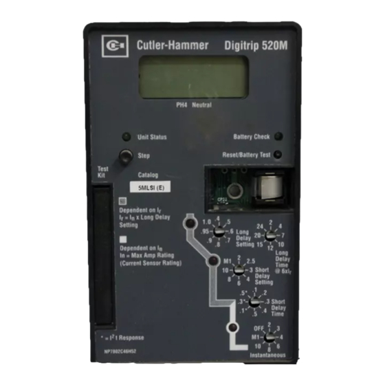
Page 2: General Description Of Digitrip Trip Units
I.L. 70C1037H02 Page 2 Figure 1.1 Digitrip 520M Trip Unit with Rating Plug NOTE: The recommendations and information contained This instruction book specifically covers the application of herein are based on experience and judgement, but Digitrip Trip Units, as illustrated in Figure 1.1, installed in should not be considered to be all inclusive or to cover Magnum and Magnum DS Breakers. - Page 3 I.L. 70C1037H02 Page 3 Table 1.1 Protection Types Available for Digitrip Trip Units Trip Unit Type Digitrip 220 Digitrip 520/520i Digitrip 520M/520Mi Ampere Range 200A-3200A 200A-6300A 200A-6300A RMS Sensing Protection and Coordination Protection Ordering Options LSI,LSIG/WLSIG MLSI,MLSIG, MLSIA/MWLSIG Fixed Rating Plug (In) Overtemperature Trip Long Long Delay Setting...
-
Page 4: Protection
I.L. 70C1037H02 Page 4 The Digitrip 220, 520, and 520M trip units may be applied 1.2 Mode of Trip and Status Information on both 50 and 60 H z systems. On all DT20 units, a green light emitting diode (LED), labeled Status, blinks approximately once each second to Digitrip DT20 family of trip units are microprocessor- indicate that the trip unit is operating normally. -
Page 5: Trip Unit/Rating Plug Removal
I.L. 70C1037H02 Page 5 Figure 1.2 Installation of the Digitrip Unit into a Magnum Breaker (Side View) CAUTION DO NOT FORCE THE RATING PLUG INTO THE CAV- ITY. Use a 1/8" (3 mm) wide screwdriver to tighten the M4 screw and secure the plug and the trip unit to the circuit breaker (see Figure 1.3). -
Page 6: Wiring
I.L. 70C1037H02 Page 6 1.4 Wiring The internal components of the breaker, and how they are wired out to the breaker secondary contacts, are shown in the breaker master connection diagram provided as Appendix C. 1.5 Plexiglass Cover A clear, tamper-proof, plexiglass door sits on the breaker cover. -
Page 7: Display Feature (520M Family Only)
I.L. 70C1037H02 Page 7 Overload (Digitrip in overload mode) Pushing the Step button while the unit is in the OL mode will have the unit again display the overload current value. HELP This message can indicate more than one prob- lem with the trip unit. -
Page 8: Low Energy Trip Actuator
I.L. 70C1037H02 Page 8 When the functional protection settings are exceeded, the located under the black molded platform on which the Digitrip unit supplies a trip signal to the Trip Actuator. As a Digitrip unit is supported. The Trip Actuator contains a result, all tripping operations initiated by the protection permanent magnet assembly, moving and stationary core functions of the Digitrip Trip Unit are performed by its... -
Page 9: General
I.L. 70C1037H02 Page 9 2.3.1 General CAUTION When the Digitrip 520 family includes ground fault protec- tion features, the distribution system characteristics (for IF THE SENSOR CONNECTIONS ARE INCORRECT, A example, system grounding, number of sources, number NUISANCE TRIP MAY OCCUR. ALWAYS OBSERVE and location of ground points, and the like) must be THE POLARITY MARKINGS ON THE INSTALLATION considered along with the manner and location in which... -
Page 10: Current Sensors (Magnum Frames Less Than Or Equal To 3200A)
I.L. 70C1037H02 Page 10 Table 2.2 Ground (Earth) Fault Current Settings rating specified on the plug label. The current sensor rating can be viewed through openings in the back of the Ground Fault Current Settings breaker. (Amperes) Installed 2.5 Current Sensors (Magnum Frames greater than 3200A) Sensor/ Rating Plug The six (3-pole) or eight (4-pole) current sensors installed... - Page 11 I.L. 70C1037H02 Page 11 S o u rc e B la c k K 1 -2 Trip A c tu a to r K 1 -3 D ig itrip 5 2 0 w ith G F 1 0 :1 K 1 -9 K 1 -8 R /1 K 1 -7...
- Page 12 I.L. 70C1037H02 Page 12 Figure 2.4 Digitrip Neutral Sensor Types S ou rce B lac k K 1-2 Trip A ctu a to r K 1-3 D ig itrip 52 0 w ith G F 10 :1 K 1-9 K 1-8 R /1 K 1-7 K 1-6...
- Page 13 I.L. 70C1037H02 Page 13 Figure 2.6 Source Ground Fault Sensing Scheme for 3200A Frame Tw o s ta n d a rd IA s e c o n d a ry s e n s o rs w ith p rim a ry in s e rie s a n d s e c o n d a rie s in p a ra lle l m a y b e u s e d .
- Page 14 I.L. 70C1037H02 Page 14 Figure 2.8 Zero Sequence Sensing Scheme for 3200A Frame I /2 I /2 I /2 I /2 i /2 i /2 i /2 Internal Digitrip S ensor i /2 i /2 N eutral S ensors W ired in a Loop C on figuration G round Fault Notes:...
-
Page 15: Trip And Operation Indicators
I.L. 70C1037H02 Page 15 memory. The embedded software then determines 3.4 Zone Interlocking (520 family only) whether to initiate protection functions, including tripping the breaker through the Trip Actuator. CAUTION 3.2 Trip and Operation Indicators IF ZONE INTERLOCKING IS NOT TO BE USED (I.E., The LEDs on the face of the trip unit, shown in Fig- ONLY STANDARD TIME-DELAY COORDINATION IS ures 1.1 and 3.3 to 3.9, flash red to indicate the reason for... - Page 16 (L ine/U ppe r) G roun d A la rm / Trip Po w er S up ply Actuator (O ption a l fo r 5 20 M ) M akin g C urrent R e lease C ircuitry FE T (S ee S e ctio n 3.3 ) C urren t S ensors Trip LE D...
- Page 17 I.L. 70C1037H02 Page 17 Figure 3.2 Digitrip 220 LI Figure 3.3 Digitrip 520 LSI Figure 3.5 Digitrip 520i WLSIG Figure 3.4 Digitrip 520 LSIG Effective 8/13/99 Courtesy of NationalSwitchgear.com...
- Page 18 I.L. 70C1037H02 Page 18 Figure 3.6 Digitrip 520M MLSI Figure 3.7 Digitrip 520M MLSIA Figure 3.8 Digitrip 520M MLSIG Figure 3.9 Digitrip 520Mi MWLSIG Effective 8/13/99 Courtesy of NationalSwitchgear.com...
-
Page 19: Protection Settings
I.L. 70C1037H02 Page 19 4.0 PROTECTION SETTINGS 4.3 Long Delay Time Setting 4.1 General There are 8 available Long Delay Time Settings, as illustrated in Figure 4.2, ranging from 2 to 24 seconds. Before placing any circuit breaker in operation, set each These settings are the total clearing times when the trip unit protection setting to the values specified by the current value equals 6 times ( I r). -
Page 20: Short Delay Current Setting
I.L. 70C1037H02 Page 20 Figure 4.3 Long Time Memory (LTM) Jumper The action of the LTM must be considered when perform- ing multiple Long Delay Time tests (see Section 5.4). 4.4 Short Delay Current Setting There are 8 available Short Delay Current Settings, as illustrated in Figure 4.4. -
Page 21: Ground Fault Current Setting
I.L. 70C1037H02 Page 21 Available S etting s S ettin g Inst. 2, 3, 4, 6, 8, x n I 10, M 1, O FF * In M ultiples of R ating P lug A m p eres ( n) M 1 va lue is sp ecified on ra tin g plug. -
Page 22: When To Test
I.L. 70C1037H02 Page 22 CAUTION CAUTION TESTING A CIRCUIT BREAKER WHILE IT IS IN- BEFORE PLUGGING A TEST KIT INTO THE TEST SERVICE AND CARRYING LOAD CURRENT IS NOT PORT, PLACE THE LTM JUMPER IN THE INACTIVE RECOMMENDED. POSITION (SEE FIGURE 4.3). AFTER TESTING, RE- TURN THE LTM JUMPER TO ITS ORIGINAL POSITION. -
Page 23: Battery
I.L. 70C1037H02 Page 23 WARNING PERSONAL INJURY CAN OCCUR WHEN WORKING ON POWER SYSTEMS. ALWAYS TURN OFF POWER SUPPLYING BREAKER BEFORE CONDUCTING TESTS. TEST OUT OF THE CELL, IF POSSIBLE. THERE IS A HAZARD OF ELECTRICAL SHOCK OR BURN WHENEVER WORKING IN OR AROUND ELEC- TRICAL EQUIPMENT. -
Page 24: Battery Installation And Removal
I.L. 70C1037H02 Page 24 6.3 Battery Installation and Removal Duracell, Inc. DL 1/3N Berkshire Corporate Park The 3-volt lithium cell battery (see Figure 6.1) is easily Bethel, CT 06801 removed and replaced. The battery is located in the cavity 1-800-551-2355 adjacent to the rating plug mounting screw, but is not part (www.duracell.com) of the rating plug. -
Page 25: Record Keeping
I.L. 70C1037H02 Page 25 9.0 REFERENCES CAUTION 9.1 Magnum and Magnum DS Circuit Breakers BEFORE YOU FIT THE RATING PLUG INTO THE TRIP I.B. 2C12060 Magnum DS Breaker Instructions UNIT, BE SURE TO CHECK THAT THE SENSOR RATING MATCHES THAT PRINTED ON THE RATING I.B. - Page 26 I.L. 70C1037H02 Page 26 DIGITRIP TRIP FUNCTION SETTINGS Circuit No./Address Breaker Shop Order Reference PER UNIT MULTIPLIERS I r Continuous Ampere Rating Rating Plug Amperes ( I n) = LDS x I n Ampere Trip Per Unit Equivalent Function Setting Multi Setting Time Delay...
- Page 27 I.L. 70C1037H02 Page 27 DIGITRIP AUTOMATIC TRIP OPERATION RECORD Circuit No./Address Breaker Shop Order Reference Trip Function Settings Reference Orig. 0 Rev. 1 Rev. 2 Rev. 3 Instantaneous Long Delay Setting Long Delay Time Short Setting Short Time Ground Fault Setting Ground Fault Time Setting Date...
- Page 28 I.L. 70C1037H02 Page 28 GROUND FAULT TEST RECORD FORM Ground Fault Test Record should be retained by those in charge of the building's electrical installation in order to be available to the authority having jurisdiction. Test Date Circuit Breaker Results Tested by Number Figure 8.3 Typical Performance Test Record Form...
-
Page 29: Appendix A Zone Interlocking Examples
I.L. 70C1037H02 Page 29 Fault at location 2 NOTICE The feeder breaker trip unit will initiate the trip in 0.045 seconds to clear the fault and will send an interlock- ing signal to the main trip unit. The main trip unit will begin THE PROVISION FOR ZONE INTERLOCKING IS to time out and, in the event that the feeder breaker Z2 STANDARD ON MAGNUM CIRCUIT BREAKERS WITH... - Page 30 I.L. 70C1037H02 Page 30 - B 7 C ontact - B 9 C o nta ct - B 8 C o nta ct Figure A.1 Typical Zone Interlocking Figure A.2 Typical Zone Interlocking Connections with Two Main Breakers (M1, M2) and a Tie Breaker (T) Effective 8/13/99 Courtesy of NationalSwitchgear.com...
-
Page 31: Appendix B Troubleshooting Guide
I.L. 70C1037H02 Page 31 Appendix B Troubleshooting Guide Symptom Probable Cause Possible Solution(s) References Unit status LED is not Current thru breaker is <25% No problem. Status LED will blinking. of sensor rating. not operate with breaker currents <25% of sensor rating. - Page 32 I.L. 70C1037H02 Page 32 Symptom Probable Cause Possible Solution(s) References Effective 8/13/99 Courtesy of NationalSwitchgear.com...
-
Page 33: Appendix C Typical Breaker Master Connection Diagram
I.L. 70C1037H02 Page 33 Appendix C Typical Breaker Master Connection Diagram Effective 8/13/99 Courtesy of NationalSwitchgear.com... - Page 34 I.L. 70C1037H02 Page 34 This instruction booklet is published solely for information purposes and should not be considered all inclusive. If further information is required, consult Cutler-Hammer, Inc. The sale of the product shown in this literature is subject to the terms and conditions outlined in appropriate Cutler-Hammer, Inc., selling policies or other contractual agreements between the parties.
- Page 35 I.L. 70C1037H02 Page 35 Effective 8/13/99 Courtesy of NationalSwitchgear.com...
- Page 36 I.L. 70C1037H02 Page 36 Cutler-Hammer Pittsburgh, PA U.S.A. Effective 8/13/99 Printed in U.S.A. Effective 8/13/99 Courtesy of NationalSwitchgear.com...
Need help?
Do you have a question about the Cutler-Hammer Digitrip 520M and is the answer not in the manual?
Questions and answers