Table of Contents
Advertisement
Instructions for Installation, Operation and Maintenance of
Type DHP-VR Vacuum Replacement Circuit Breakers for DHP Switchgear
I.B. 6513C80G Supersedes I.B. 6513C80F dated November 2003
Effective March 2007
I.B. 6513C80G
For more information visit:
www.EatonElectrical.com
Courtesy of NationalSwitchgear.com
Advertisement
Table of Contents

Related Manuals for Eaton Cutler-Hammer DHP-VR Series


Summary of Contents for Eaton Cutler-Hammer DHP-VR Series
- Page 1 Instructions for Installation, Operation and Maintenance of Type DHP-VR Vacuum Replacement Circuit Breakers for DHP Switchgear I.B. 6513C80G Supersedes I.B. 6513C80F dated November 2003 Effective March 2007 I.B. 6513C80G For more information visit: www.EatonElectrical.com Courtesy of NationalSwitchgear.com...
- Page 2 Effective: March 2007 I.B. 6513C80G Courtesy of NationalSwitchgear.com...
- Page 3 Instruction Book Effective: March 2007 Page iii WARNING WARNING THE CIRCUIT BREAKERS DESCRIBED IN THIS BOOK ARE DESIGNED AND TESTED TO OPERATE IMPROPERLY INSTALLING OR MAINTAINING WITHIN THEIR NAMEPLATE RATINGS. OPERATION THESE PRODUCTS CAN RESULT IN DEATH, OUTSIDE OF THESE RATINGS MAY CAUSE THE SERIOUS PERSONAL INJURY OR PROPERTY EQUIPMENT TO FAIL, RESULTING IN DEATH, DAMAGE.
-
Page 4: Table Of Contents
Instruction Book Page iv Effective: March 2007 TABLE OF CONTENTS PAGE SECTION 1 INTRODUCTION Available DHP-VR Breakers ............................1 SECTION 2 SAFE PRACTICES ......................................5 SECTION 3 RECEIVING, HANDLING AND STORAGE Receiving ..................................6 Handling ..................................6 Storage ..................................7 DHP-VR Weights ................................7 SECTION 4 INSTALLATION Initial Inspection and Operation .......................... - Page 5 Instruction Book Effective: March 2007 Page v PAGE Interlocks ..................................29 5-4.1 Breaker-Cell Coding Plates ..........................29 5-4.2 Levering-in Interlock ............................29 5-4.3 Anti-Close Interlock ............................30 5-4.4 Floor Tripping and Closing Spring Release Interlocks .................30 5-4.5 Rail Latch ................................30 Miscellaneous Items ...............................32 5-5.1 Ground Contact ..............................32 5-5.2 MOC and TOC Switch Operations ........................32...
- Page 6 Instruction Book Page vi Effective: March 2007 Page MOC Drive Spring ..............................13 Drive Spring Adjusted for 0 to 1 MOC Switch.....................13 Drive Spring Adjustment Graphic ........................13 Checking Drive Spring for Proper Adjustment for One Installed Moc Switch ..........13 Drive Spring Shown Adjusted for 2 MOC Switches ...................14 4-6a Drive Spring Shown Adjusted for 3 MOC Switches ...................14 4-6b...
-
Page 7: Section 1 Introduction
Instruction Book Effective: March 2007 Page 1 S E C T I O N 1 : I N T R O D U C T I O N WARNING The purpose of this book is to provide instructions for SATISFACTORY PERFORMANCE OF THESE unpacking, storage, installation, operation and BREAKERS IS CONTINGENT UPON PROPER maintenance of Type DHP-VR Vacuum Replacement... -
Page 8: Outline And Dimensions (Inches) Type Dhp-Vr Breakers (5 Kv, 250 Mva Rating)
Instruction Book Page 2 Effective: March 2007 R a t i n g 22.40 21.88 48.76 24.03 250U 22.40 21.88 48.76 24.03 Figure 1-1 Outline and Dimensions (inches) Type DHP-VR Breakers (5 kV, 250 MVA Rating) For more information visit: www.EatonElectrical.com I.B6513C80G Courtesy of NationalSwitchgear.com... -
Page 9: Outline And Dimensions (Inches) Type Dhp-Vr Breakers (5 Kv, 350 Mva Rating)
Instruction Book Effective: March 2007 Page 3 R a t i n g 3 5 0 2 2 . 6 5 2 2 . 3 8 5 7 . 1 6 2 9 . 3 8 Figure 1-2 Outline and Dimensions (inches) Type DHP-VR Breakers (5 kV, 350 MVA Rating) IB6513C80G For more information visit: www.EatonElectrical.com... -
Page 10: Outline And Dimensions (Inches) Type Dhp-Vr Breakers (7.5 Kv And 15 Kv Ratings)
Instruction Book Page 4 Effective: March 2007 R a t i n g 60.75 31.25 34.81 60.75 31.25 34.81 750C 73.75 31.00 38.35 1000 73.75 31.00 38.35 Figure 1-3 Outline and Dimensions (inches) Type DHP-VR Breakers (7.5 kV and 15 kV Ratings) For more information visit: www.EatonElectrical.com I.B6513C80G... -
Page 11: Section 2 Safe Practices
Instruction Book Effective: March 2007 Page 5 • Do not work on a closed breaker or a breaker with S E C T I O N 2 : S AF E P R AC T I C E S closing springs charged. The closing spring should be discharged and the main contacts open before work Type DHP-VR breakers are equipped with high ing on the breaker. -
Page 12: Section 3 Receiving, Handling And Storage
Instruction Book Page 6 Effective: March 2007 S ECT IO N 3: R EC E I VI NG , H AN D LI NG AN D S T O R AG E Type DHP-VR circuit breakers are subjected to complete factory production tests and inspection before being packed. -
Page 13: Storage
Instruction Book Effective: March 2007 Page 7 Once the lifting yoke is securely seated in the lifting holes, the breaker can be carefully lifted and moved. 3-4 DHP-VR WEIGHTS Keep in mind, however, the faceplate on all 7.5 or 15 kV. DHP-VR breakers must be removed to use a lifting yoke. -
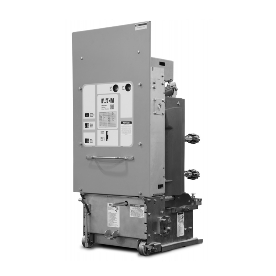
Page 14: Front External View Of Dhp-Vr Breaker (5 Kv, 250 Mva Rating)
Instruction Book Page 8 Effective: March 2007 Figure 3-2 Front External View of DHP-VR Breaker (5kV, 250 MVA Rating) For more information visit: www.EatonElectrical.com I.B6513C80G Courtesy of NationalSwitchgear.com... -
Page 15: Rear External View Of Dhp-Vr Breaker (5 Kv, 250 Mva Rating)
Instruction Book Effective: March 2007 Page 9 Figure 3-3 Rear External View of DHP-VR Breaker (5 kV, 350 MVA Rating) IB6513C80G For more information visit: www.EatonElectrical.com Courtesy of NationalSwitchgear.com... -
Page 16: Front External View Of Dhp-Vr Breaker (7.5 And 15 Kv, 500 And 750 Mva Ratings)
Instruction Book Page 10 Effective: March 2007 Figure 3-4 Front External View of DHP-VR Breaker (7.5 and 15 kV, 500 and 750 MVA Ratings) For more information visit: www.EatonElectrical.com I.B6513C80G Courtesy of NationalSwitchgear.com... -
Page 17: Rear External View Of Dhp-Vr Breaker (7.5 And 15 Kv, 500 And 750 Mva Ratings)
Instruction Book Effective: March 2007 Page 11 Figure 3-5 Rear External View of DHP-VR Breaker (7.5 and 15 kV, 500 and 750 MVA Ratings) IB6513C80G For more information visit: www.EatonElectrical.com Courtesy of NationalSwitchgear.com... -
Page 18: Section 4 Installation
Instruction Book Page 12 Effective: March 2007 S ECT IO N 4: I NST AL L AT IO N It is only for the cases of 2 or 3 MOC switches that the drive spring adjustment is required. The adjustment is done with the breaker out of the cell, open and all springs discharged. -
Page 19: Moc Drive Spring
Instruction Book Effective: March 2007 Page 13 Step 7: When the adjustment is completed, be sure to properly replace and secure the phase barrier removed in Step 1. Figure 4-3 Drive Spring Adjustment Graphic Figure 4-1 MOC driving spring. Figure 4-4 Checking Drive Spring for Proper Adjustment for One Instaled MOC Switch Figure 4-2 Drive Spring Adjusted for 0 or 1 MOC Switch IB6513C80G... -
Page 20: Mechanism Operated Cell (Moc) Switch Pantograph Adjustment
Instruction Book Page 14 Effective: March 2007 MECHANISM OPERATED CELL (MOC) SWITCHES, THE STEPS OUTLINED IN THIS PARAGRAPH MUST BE PERFORMED BEFORE INSTALLING A REPLACEMENT DHP-VR CIRCUIT BREAKER. FAILURE TO COMPLETE THESE STEPS COULD RESULT IN EQUIPMENT DAMAGE AND/OR IMPROPER OPERATION. Inspect the MOC pantograph in keeping with the following steps and refer to Figure 4-7 additional assistance. -
Page 21: Manual Operation Check
Instruction Book Effective: March 2007 Page 15 Step 3: Check that the top surface of the pantograph 4-9 NAMEPLATE channel is adjusted so the MOC operator pin on the breaker is centered in the channel. Compare the breaker nameplate information with switchgear drawings for compatibility. -
Page 22: Snubber Adjustment
Instruction Book Page 16 Effective: March 2007 Figure 4-2 Snupper Adjustment For more information visit: www.EatonElectrical.com I.B6513C80G Courtesy of NationalSwitchgear.com... -
Page 23: Positioning Of 5 Kv Dhp-Vr Breaker
Instruction Book Effective: March 2007 Page 17 ’ using your foot or hand (Figure 4-11). When using a a. The circuit breaker s faceplate and barriers must be foot, care should be taken not to bend the lever by positioned properly and securely bolted in position, as using excessive force. -
Page 24: Lever Breaker Into Cell
Instruction Book Page 18 Effective: March 2007 Figure 4-12 Final Engagement of 7.5 or 15 kV Secondary Contact 4-12 LEVER BREAKER INTO CELL Figure 4-10 Positioning of 7.5 or 15 kV DHP-VR Breaker Trip the breaker open before attempting to lever it into the cell. -
Page 25: Removing Breaker From Cell
Instruction Book Effective: March 2007 Page 19 The breaker will move slowly toward the rear of the cell. After the breaker starts to move, it is not necessary to push (Figures 4-13 and 4-14). Continue cranking until the crank turns freely, and the breaker stops moving. When the breaker is fully engaged, the front face-plate will almost touch the cell frame angles. -
Page 26: Section 5 Description And Operation
Instruction Book Page 20 Effective: March 2007 SECTION 5: DESCRIPTION AND The primary insulation used on 5kV. DHP-VR vacuum circuit breakers is glass polyester, while the primary O P E R AT I O N insulation used on 7.5 and 15 kV. DHP-VR vacuum circuit breakers is cycloaliphatic epoxy. -
Page 27: 5-1.1 Vacuum Interrupter
Instruction Book Effective: March 2007 Page 21 5-1.3 “T” CUTOUT LOADING SPRING INDICATOR The vacuum interrupter system on all DHP-VR breakers utilizes a visible “T” cutout contact loading spring indicator. This “T” indicator is used to indicate that the Since the “T” cutout loading spring indicator is part of all loading springs are maintaining the proper contact DHP-VR breaker designs, an additional method is pressure to keep the contacts closed (Figures 5-1 and 5-... -
Page 28: 5-1.5 Phase Barriers
Instruction Book Page 22 Effective: March 2007 5-1.5 PHASE BARRIERS 5-2.2 CHARGING Figure 5-6 is a schematic view of the spring charging parts of the stored energy mechanism. WARNING The major component of the mechanism is a cam shaft assembly which consists of a drive shaft to which are DO NOT PLACE THE BREAKER IN ITS attached two closing spring cranks (one on each end), COMPARTMENT WITHOUT THE PHASE BARRIERS IN... -
Page 29: Dhp-Vr 5 Kv Design - Front Faceplate Removed
Instruction Book Effective: March 2007 Page 23 Figure 5-3 DHP-VR 5 kV Design - Front Faceplate Removed IB6513C80G For more information visit: www.EatonElectrical.com Courtesy of NationalSwitchgear.com... -
Page 30: Dhp-Vr 7.5 Or 15 Kv Design - Front Faceplate Removed
Instruction Book Page 24 Effective: March 2007 Figure 5-4 DHP-VR 7.5 or 15 kV Design - Front Faceplate Removed For more information visit: www.EatonElectrical.com I.B6513C80G Courtesy of NationalSwitchgear.com... -
Page 31: Closing Cam And Trip Linkage
Instruction Book Effective: March 2007 Page 25 F i g u r e 5 - 5 C l o s i n g C a m a n d T r i p L i n k a g e IB6513C80G For more information visit: www.EatonElectrical.com... -
Page 32: Charging Schematic
Instruction Book Page 26 Effective: March 2007 Breaker Open, Springs Discharged Breaker Closed, Springs Charged F i g u r e 5 - 6 C h a r g i n g S c h e m a t i c For more information visit: www.EatonElectrical.com I.B6513C80G... -
Page 33: 5-2.4 Tripping Operation
Instruction Book Effective: March 2007 Page 27 Figure 5-5d shows the breaker in the closed position When the CS/C contact is made, the SR closes the after the closing springs have been recharged. Note that breaker. If the CS/C contact is maintained after the the spring charging rotates the closing cam by one half breaker closes, the Y relay is picked-up. -
Page 34: Typical Dhp-Vr Dc And Ac Control Schemes
Instruction Book Page 28 Effective: March 2007 Figure 5-7 Typical DHP-VR “DC” and “AC” Control Schemes For more information visit: www.EatonElectrical.com I.B6513C80G Courtesy of NationalSwitchgear.com... -
Page 35: Interlocks
Instruction Book Effective: March 2007 Page 29 To engage the secondary contacts on the 5kV. design while the breaker is in the test position, lift the handle on the front left hand side of the breaker chassis to a horizontal position. Once the rod is pointing straight out from the breaker, push it manually to the rear until the secondaries are initially engaged. -
Page 36: 5-4.3 Anti-Close Interlock
Instruction Book Page 30 Effective: March 2007 breaker contacts are closed. DHP-VR interlocks are completely compatible with the existing levering screw located in the existing DHP or DVP assembly structure. DHP-VR 5kV. breakers utilize a levering-in interlock design that is very similar to the design used on DHP breakers. -
Page 37: Dhp-Vr Breaker (5 Kv) Floor Tripping Levers (Underneath Front View)
Instruction Book Effective: March 2007 Page 31 Figure 5-14 DHP-VR Breaker (5 kV) Rail Latch Figure 5-12 DHP-VR Breaker (5 kV) Floor Tripping Levers (Underneath Front View) Figure 5-15 DHP-VR Breaker (7.5 or 15 kV) Rail Latch Figure 5-13 DHP-VR Breaker (7.5 or 15 kV) Floor Tripping Lever (Underneath Rear View) IB6513C80G For more information visit:... -
Page 38: Miscellaneous Items
Instruction Book Page 32 Effective: March 2007 5-5 MISCELLANEOUS ITEMS 5-6 LEVERING DEVICE 5-5.1 GROUND CONTACT The purpose of the levering device is to move the breaker The ground contact is an assembly of spring loaded between the Test and Connected positions. On the 7.5 or fingers for all DHP-VR breaker designs providing a 15kV. -
Page 39: Dhp-Vr Breaker (5 Kv) Levering-In Device Nut Housing
Instruction Book Effective: March 2007 Page 33 The end of the guide tube is shaped like a steep-pitch one-turn screw thread so that when the levering shaft is rotated counter-clockwise, the rear key will catch and enter the slot and rotate the guide tube and nut, with- drawing the breaker. -
Page 40: Inspection And Maintenance
Instruction Book Page 34 Effective: March 2007 • DO NOT STAND LESS THAN ONE METER AWAY SECTION 6: INSPECTION AND FROM THE BREAKER WHEN TESTING FOR MAINTENANCE VACUUM INTEGRITY. 6-1 INTRODUCTION • FAILURE TO FOLLOW ANY OF THESE INSTRUCTIONS MAY CAUSE DEATH, SERIOUS BODILY INJURY, OR PROPERTY DAMAGE. -
Page 41: Inspection And Maintenance Procedures
Instruction Book Effective: March 2007 Page 35 6-3 INSPECTION AND MAINTENANCE PROCEDURES No./Section Inspection Item Criteria Inspection Method Corrective Action if Necessary 1. Insulation Stand off insulators, oper- No dirt Visual check Clean with lint-free cloth. ating rods, tie-bars and barriers No cracking Visual check... -
Page 42: Vacuum Interrupter Integrity Test
Instruction Book Page 36 Effective: March 2007 6-4 VACUUM INTERRUPTER INTEGRITY TEST to leakage or displacement (capacitive) current, the test unit should have sufficient volt-ampere capacity. It is Vacuum interrupters used in Type DHP-VR Vacuum recommended that the equipment be capable of Circuit Breaker Elements are highly reliable interrupting delivering 25 milliamperes for one minute. -
Page 43: Insulation
Instruction Book Effective: March 2007 Page 37 WARNING FAILURE TO REPLACE A VACUUM INTERRUPTER ASSEMBLY WHEN CONTACT EROSION MARK IS NOT VISIBLE OR WIPE IS UNSATISFACTORY, WILL CAUSE THE BREAKER TO FAIL TO INTERRUPT AND THEREBY CAUSE PROPERTY DAMAGE OR PERSONAL INJURY. -
Page 44: Primary Circuit Resistance Check
Instruction Book Page 38 Effective: March 2007 Figure 6-4 “T” Contact Wipe Indicator Example with Blue Spring (if the “T” or any portion of it is visible as shown with the breaker closed, the wipe is satisfactory, See Next Figure for Graphic of Al Possibilities) minute. -
Page 45: Closure Tm Test
Instruction Book Effective: March 2007 Page 39 ™ 6-9.1 CLOSURE TEST Introduction: The CloSure Test is a simple yet extremely effective means to determine and monitor the ability of the mechanism to close the breaker contacts fully. It provides a quantitative measure of the extra energy available in terms of over travel in inches to close the breaker contacts to their full extent. -
Page 46: Wrapping Tape Up Around Cam
Instruction Book Page 40 Effective: March 2007 to save the original fasteners for re-assembly. open position and the closing springs are discharged. Remove the transparent CloSure Tool. Remove the Step 3 - tape from the cam and stick the tape on the front right Cut a piece of one inch wide side sheet of the circuit breaker. -
Page 47: Test Tool At Hole "B
Instruction Book Effective: March 2007 Page 41 Figure 6-11 Attaching CloSure Test Tool at Hole “B” Figure 6-14 Top View of Cam and Marker Interface Figure 6-15 Move Marker 15 to Right Figure 6-12 Manually Charging Closing Springs Figure 6-13 Manually Closing Circuit Breaker with Marker in “... -
Page 48: Move Marker 15° To Left
Instruction Book Page 42 Effective: March 2007 Figure 6-16 Move Marker 15 to left Figure 6-19 Illustrative Testing Tape Sample Figure 6-17 Remove Marked Masking Tape from Cam Figure 6-20 Front View of CloSure Tool Showing Mounting/Testing Hole Locations (6352C49H01) Figure 6-18 Place Tape on Right Side Panel of Breaker For more information visit: www.EatonElectrical.com... -
Page 49: Lubrication
Instruction Book Effective: March 2007 Page 43 Breaker Approximate Upper Lower Marker Line Mechanism Mounting Mounting Placement Cabinet Hole Hole Hole Width (inch) DHP-VR VCPW-ND 20/21 VCP-W VVP-WG, VCP-WGR VCP-WR W-VAC, W-VACR Figure 6-21 Typical Circuit Breaker Front View with Table 6.4 Closure Tool Mounting/Testing Locations by CloSure... -
Page 50: Troubleshooting
Instruction Book Page 44 Effective: March 2007 6-11 TROUBLESHOOTING CHART (CONTINUED ON NEXT PAGE) SYMPTOM INSPECTION AREA PROBABLE DEFECTS FAILS TO CLOSE • Closing Springs not charged • Control Circuit • Control Power (Fuse blown or switch off) • Secondary Disconnects •... - Page 51 Instruction Book Effective: March 2007 Page 45 SYMPTOM INSPECTION AREA PROBABLE DEFECTS FAILS TO CLOSE • Closing Springs Charged but • No Closing Sound • Control Power breaker does not close (Close Coil does not pick up) (Fuse blown or switch off) •...
- Page 52 Instruction Book Page 46 Effective: March 2007 SYMPTOM INSPECTION AREA PROBABLE DEFECTS FAILS TO TRIP • No Trip Sound • Control Circuit • Control Power (Fuse blown or switch off) • Secondary Disconnect • Auxiliary Switch (a contact not making poor or burned) •...
-
Page 53: Renewal Parts
Instruction Book Effective: March 2007 Page 47 SECTION 7: RENEWAL PARTS 7-1 GENERAL In order to minimize production downtime, it is recommended that an adequate quantity of spare parts be carried in stock. The quantity will vary from customer to customer, depending upon the service severity and continuity requirements. - Page 54 Instruction Book Page 48 Effective: March 2007 For more information visit: www.EatonElectrical.com I.B6513C80G Courtesy of NationalSwitchgear.com...
- Page 55 E f fe ct i ve : Ma r ch 2007 For DHP Switchgear Eaton Corporation Cutler-Hammer business unit 1000 Cherrington Parkway Moon Township, PA 15108-4312 tel: 1-800-525-2000 www.cutler-hammer.eaton.com © 2003 Eaton Corporation All Rights Reserved Printed in USA Publication No. IB6513C80G (ISI) March 2007 Courtesy of NationalSwitchgear.com...
- Page 56 Effective: March 2007 © 2003 Eaton Corporation All Rights Reserved Printed in USA Publication No. IB6513C80G (ISI) March 2007 I.B. 6513C80G Courtesy of NationalSwitchgear.com...
Need help?
Do you have a question about the Cutler-Hammer DHP-VR Series and is the answer not in the manual?
Questions and answers