
Related Manuals for Bosch Rexroth VT-HNC100 3X Series


Summary of Contents for Bosch Rexroth VT-HNC100 3X Series
- Page 1 Digital axis control RE 30139-B/12.14 Replaces: 10.11 English Type VT-HNC100...3X Operating Instructions...
- Page 2 © This document, as well as the data, specifications and other information set forth in it are the exclusive property of Bosch Rexroth AG. It may not be reproduced or given to third parties without our consent.
-
Page 3: Table Of Contents
10.2 Disassembling the digital axis control .............43 10.3 Preparing the components for storage/further use ......... 43 11 Disposal ......................44 11.1 Environmental protection ................44 11.2 Return to Bosch Rexroth.................44 11.3 Packagings .....................44 11.4 Materials used..................44 11.5 Recycling ....................44 12 Extension and conversion ................45 13 Troubleshooting ...................45... -
Page 4: About This Document
4/48 Bosch Rexroth AG VT-HNC100...3X | RE 30139-B/12.14 About this document About this document Validity of the documentation This documentation is applicable for the digital axis controls VT-HNC100-...-3X/C..., VT-HNC100-...-3X/P..., VT-HNC100-...-3X/N... and VT-HNC100-...-3X/E... of the VT-HNC100 product family of the 3X/... series. . -
Page 5: Illustration Of Information
RE 30139-B/12.14 | VT-HNC100...X Bosch Rexroth AG 5/48 About this document Illustration of information Consistent safety notes, symbols, terms and abbreviations are used so that you can quickly and safely work with your product using this documentation. For a better understanding, they are explained in the following sections. - Page 6 6/48 Bosch Rexroth AG VT-HNC100...3X | RE 30139-B/12.14 About this document 1.3.3 Denominations The following denominations are used in this documentation: Table 4: Denominations Denomination Meaning VT-HNC100...3X Digital axis control WIN-PED® Operating software WIN-PED® 6 or WIN-PED® 7 for VT-HNC100...3X...
-
Page 7: Safety Instructions
2 “Safety instructions”. Any use deviating from the intended use is not intended and thus not admissible. Bosch Rexroth AG does not assume any liability for damages caused by not intended use. The user assumes all risks involved with not intended use. -
Page 8: Qualification Of Personnel
WIN-PED® as well as first steps for operation are available on the Internet under http://www.boschrexroth.com/hnc100. We recommend the participation in a product-specific training of Bosch Rexroth. Rexroth offers training support in specific fields. An overview of the training contents are available on the Internet under: http://www.boschrexroth.de/didactic. -
Page 9: Product- And Technology-Related Safety Instructions
RE 30139-B/12.14 | VT-HNC100...X Bosch Rexroth AG 9/48 Safety instructions • The information given in the product documentation with regard to the use of the supplied components are only application samples and recommendations. The machine manufacturer and system installer must check the suitability of... -
Page 10: Personal Safety Equipment
10/48 Bosch Rexroth AG VT-HNC100...3X | RE 30139-B/12.14 Scope of delivery Personal safety equipment Check specified personal protection for completeness and protective effect and have it available (please observer customer requirements and personal protection list!) Scope of delivery The delivery contents include: •... -
Page 11: Information On This Product
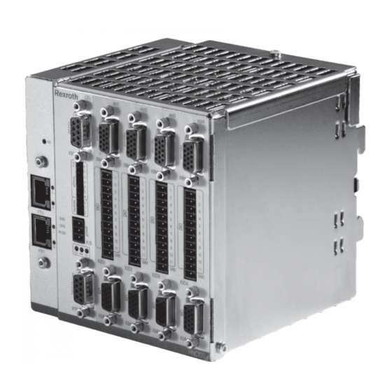
RE 30139-B/12.14 | VT-HNC100...X Bosch Rexroth AG 11/48 Information on this product Information on this product Performance description The digital axis control VT-HNC100...3X is a programmable NC control designed for one to four controlled electro-hydraulic axes. The VT-HNC100...3X can be... - Page 12 12/48 Bosch Rexroth AG VT-HNC100...3X | RE 30139-B/12.14 Information on this product Setup example Fig. 1: System setup The main operating ranges of VT-HNC100...3X include machine tools, plastic machines, special-purpose machines, presses and transfer systems. The technology functions include: • Process programming •...
-
Page 13: Product Identification
RE 30139-B/12.14 | VT-HNC100...X Bosch Rexroth AG 13/48 Information on this product The preparation of user-specific data sets forms the basis for the function of the VT-HNC100...3X. These data sets are created on the PC and submitted to the VT-HNC100...3X via the serial interface or optionally the TCP/IP. The connection between user program and data sets is referred to as project. -
Page 14: Pin Assignments
14/48 Bosch Rexroth AG VT-HNC100...3X | RE 30139-B/12.14 Information on this product Pin assignments 4.4.1 Pin assignment VT-HNC100-C-3X/... (Compact) The pins marked with “reserved” are reserved and must not be connected! Encoder RS232 Shield 24 Venc +5 V – Clk... - Page 15 RE 30139-B/12.14 | VT-HNC100...X Bosch Rexroth AG 15/48 Information on this product 4.4.2 Pin assignment VT-HNC100-1-3X/... (1-axis version) The pins marked with “reserved” are reserved and must not be connected! RS232 Slot 1 X8M1 Encoder Incremental – B (Inc) + CLK (SSI)
- Page 16 16/48 Bosch Rexroth AG VT-HNC100...3X | RE 30139-B/12.14 Information on this product 4.4.3 Pin assignment VT-HNC100-2-3X/... (2-axis version) The pins marked with “reserved” are reserved and must not be connected! RS232 Slot 1 X8M1 Encoder Slot 2 X8M2 Incremental – B (Inc)
- Page 17 RE 30139-B/12.14 | VT-HNC100...X Bosch Rexroth AG 17/48 Information on this product 4.4.4 Pin assignment VT-HNC100-3-3X/... (3-axis version) The pins marked with “reserved” are reserved and must not be connected! RS232 Slot 1 X8M1 Encoder Slot 2 X8M2 Slot 3 X8M3 Incremental –...
- Page 18 18/48 Bosch Rexroth AG VT-HNC100...3X | RE 30139-B/12.14 Information on this product 4.4.5 Pin assignment VT-HNC100-4-3X/... (4-axis version) The pins marked with “reserved” are reserved and must not be connected! RS232 Slot 1 X8M1 Encoder Slot 1 X2D1 Slot 1 X2A1...
-
Page 19: Transport And Storage
RE 30139-B/12.14 | VT-HNC100...X Bosch Rexroth AG 19/48 Transport and storage Transport and storage There are no special transport instructions for this product. You must, however, observe the notes in chapter 2 “General safety notes” and comply with the ambient conditions for storage and transport which are detailed in the technical data of data sheet 30139. -
Page 20: Assembly
20/48 Bosch Rexroth AG VT-HNC100...3X | RE 30139-B/12.14 Assembly Assembly NOTE Risk of short circuit! Water may condense within the housing! Let the VT-HNC100...3X acclimate itself for several hours, as otherwise water may condense in the housing. The housing of the VT-HNC100...3X/ is perforated. According to the existing protection class, dirt and fluids may easily enter and cause failures and a short circuit! Safe functioning of the VT-HNC100...3X/ is thus no longer ensured. -
Page 21: Recommended Accessories
Assembly Recommended accessories The following accessories are recommended for the connection of the VT-HNC100...3X axis control. These accessories are not included in the scope of delivery, and can be ordered separately at Bosch Rexroth. Table 6: Accessories Component Material number... - Page 22 22/48 Bosch Rexroth AG VT-HNC100...3X | RE 30139-B/12.14 Assembly Supply of external components When supplying a 24 V encoder, the input voltage of the HNC100...3X at X1S must comply with the encoder's requirements (e.g. 24 V +/–5 %, residual ripple < 500 mV).
-
Page 23: Vt-Hnc100
RE 30139-B/12.14 | VT-HNC100...X Bosch Rexroth AG 23/48 Assembly VT-HNC100...3X mechanical assembly Assemble the VT-HNC100...3X on a top hat rail as follows: Carefully engage the rear wall of the VT-HNC100...3X housing on a top hat rail and check for safe seat. The mechanical contact points on the elastic rear wall of the VT-HNC100...3X allow for a safe seat on the top hat rail and the... - Page 24 24/48 Bosch Rexroth AG VT-HNC100...3X | RE 30139-B/12.14 Assembly 6.4.1 HNC100...3X wiring Use of pre-assembled breakout cables at the X8M encoder connector interface and the analog I/O X2A Fig. 5: Breakout cable with HD-SUB, 15-pole 1 Shield clamp: The open end of the assembled breakout cable is connected with the terminal block.
- Page 25 RE 30139-B/12.14 | VT-HNC100...X Bosch Rexroth AG 25/48 Assembly Max. length of the cable: 2 m NOTE: On the side of the breakout cable, all wires must be connected to the terminal strip. Otherwise there is a risk of short circuit! The earthing of the control cabinet must be considered accordingly.
- Page 26 26/48 Bosch Rexroth AG VT-HNC100...3X | RE 30139-B/12.14 Assembly Table 7: Pin assignment Slot X2A1 AIO (analog) Slot 1 X8M1 Encoder Incremental Black Pin 1 Vin 1 + Pin 1 – B Pink Pin 2 Vin 1 – Pin 2...
- Page 27 RE 30139-B/12.14 | VT-HNC100...X Bosch Rexroth AG 27/48 Assembly wall, i.e the earth. The low-resistance connection of the conductibly coated DIN rail taddo the control cabinet rear wall is important. 2 VT-HNC100...3X Compact shield system The cable shields are connected with the VT-HNC100 housing via the shield pin of the Micro Combicon connector.
- Page 28 28/48 Bosch Rexroth AG VT-HNC100...3X | RE 30139-B/12.14 Assembly Table 8: Pin assignment Black Slot X8M Encoder Slot X2A (Analog) Pin 8 Shield Pin 8 Shield Brown Pin 7 24 Venc Pin 7 24 Vsens Grey Pin 6 +5 V...
- Page 29 RE 30139-B/12.14 | VT-HNC100...X Bosch Rexroth AG 29/48 Assembly 6.4.2 wiring instructions for pressure transducers The figure shows a wiring example. Screening is not taken into account. See chapter 6.4.1 “VT-HNC100...3X wiring”. Fig. 11: wiring for pressure transducers...
- Page 30 30/48 Bosch Rexroth AG VT-HNC100...3X | RE 30139-B/12.14 Assembly Fig. 12: wiring for pressure transducers...
- Page 31 RE 30139-B/12.14 | VT-HNC100...X Bosch Rexroth AG 31/48 Assembly Fig. 13: Forwarding a pressure transducer signal (not for Compact version)
- Page 32 32/48 Bosch Rexroth AG VT-HNC100...3X | RE 30139-B/12.14 Assembly 6.4.3 Description of the lEDs At the front side of the VT-HNC100...3X unit, there are the following 3 LED displays: • 3.3 V: Voltage supply of the VT-HNC100...3X is OK. • RUN: VT-HNC100...3X has been initialized and is in “RUN”. The LED flashes if the VT-HNC100...3X has not been initialized.
- Page 33 RE 30139-B/12.14 | VT-HNC100...X Bosch Rexroth AG 33/48 Assembly Fig. 15: VT-HNC100 address with CANopen Fig. 16: Baud rate for CANopen...
- Page 34 34/48 Bosch Rexroth AG VT-HNC100...3X | RE 30139-B/12.14 Assembly 6.4.5 PROFIBUS DP The PROFIBUS DP interface as well as the operation of the VT-HNC100...3X via CANopen is described in detail in the online help. Fig. 17: RROFIBUS DP interface...
- Page 35 RE 30139-B/12.14 | VT-HNC100...X Bosch Rexroth AG 35/48 Assembly Fig. 18: Address setting for PROFIBUS DP...
- Page 36 36/48 Bosch Rexroth AG VT-HNC100...3X | RE 30139-B/12.14 Assembly Fig. 19: PROFIBUS DP baud rate 6.4.6 Setting the address switch The address switch is located at the front side of the housing of the VT-HNC100...3X A binary setting of 1 to 127 addresses is possible.
-
Page 37: Commissioning
RE 30139-B/12.14 | VT-HNC100...X Bosch Rexroth AG 37/48 Commissioning Commissioning First commissioning NOTE Uncontrolled connection or disconnection of plug-in connectors! The device might be destroyed. Before installation works, and before connecting or disconnecting plug-in connectors to or from the device, the device must be disconnected from the voltage supply or reliably de-energized. -
Page 38: Commissioning Software Win-Ped® 6 And Win-Ped® 7
38/48 Bosch Rexroth AG VT-HNC100...3X | RE 30139-B/12.14 Commissioning Further information on operation, project planning, programming and diagnosis of the control system with WIN-PED® 6 is available in the help menus of the program. Commissioning software wIN-PED® 6 and wIN-PED® 7 For commissioning and for later operation, the user can apply the PC program WIN-PED®. - Page 39 RE 30139-B/12.14 | VT-HNC100...X Bosch Rexroth AG 39/48 Commissioning 7.3.1 HNC - PC connection via serial interface Establish the connection between the VT-HNC100...3X and your PC as follows: Fig. 20: Connection and required accessories 7.3.2 HNC - PC connection via TCP/IP For Ethernet-capable VT-HNCs, TCP/IP is optionally available as alternative for the serial interface.
- Page 40 40/48 Bosch Rexroth AG VT-HNC100...3X | RE 30139-B/12.14 Commissioning The control types are listed on the download site for WIN-PED®. The HNC software must be installed after download: Follow the installation instructions. After having installed WIN-PED® and the control types, the WIN-PED®...
-
Page 41: Operation
RE 30139-B/12.14 | VT-HNC100...X Bosch Rexroth AG 41/48 Operation the communication between PC and VT-HNC, the initializing of the control, the archiving of data in the control and the acquisition of data from the control. Creating a new project using the installed HNC software. -
Page 42: Maintenance And Repair
Rexroth AG. For repair and maintenance works, send the unit to the service address specified in chapter 15. Devices returned to Bosch Rexroth for repair must be sent in original packaging. Repaired devices are returned with default settings. User-specific settings are not accepted. The user must transfer all appropriate... -
Page 43: Disassembly And Replacement
RE 30139-B/12.14 | VT-HNC100...X Bosch Rexroth AG 43/48 Disassembly and replacement 10 Disassembly and replacement 10.1 Preparing for disassembly NOTE The device might be destroyed! Decommission the entire system as described in the overall system manual. De-energize the device and all connected components. -
Page 44: Disposal
Thus, dispose of the VT-HNC100...3X and the packaging material in accordance with the currently applicable national regulations in your country. 11.2 Return to Bosch Rexroth The products manufactured by us can be returned to us for disposal purposes at no costs. However, the precondition is that there are no spurious adherences or any other contamination. -
Page 45: Extension And Conversion
RE 30139-B/12.14 | VT-HNC100...X Bosch Rexroth AG 45/48 Extension and conversion recovered by means of special separation procedures as well. If the products contain batteries or accumulators, these have to be removed before recycling and furnished to the battery recycling, if possible. -
Page 46: Technical Data
46/48 Bosch Rexroth AG VT-HNC100...3X | RE 30139-B/12.14 Technical data 14 Technical data Technical data vary according to the version of the VT-HNC100...3X. A detailed description of you axis control is available in the data sheet RE 30139. In addition, you can here find data on the two bus systems PROFINET RT... -
Page 47: Appendix
RE 30139-B/12.14 | VT-HNC100...X Bosch Rexroth AG 47/48 Appendix 15 Appendix 15.1 Address directory 15.1.1 Contact person for repair Bosch Rexroth AG Service Industriehydraulik [Industrial hydraulics] Bgm.-Dr. Nebel-Str. 8 97816 Lohr am Main Germany http://www.boschrexroth.com/service eMail: service@boschrexroth.de 15.1.2 Contact person for support Bosch Rexroth AG Zum Eisengießer 1... - Page 48 Bosch Rexroth AG Hydraulics Zum Eisengießer 1 97816 Lohr am Main Germany Phone +49 9352 18-0 +49 9352 18-23 58 info@boschrexroth.de www.boschrexroth.com Subject to change without notice Printed in Germany RE 30139-B/12.14...
Need help?
Do you have a question about the Rexroth VT-HNC100 3X Series and is the answer not in the manual?
Questions and answers