Table of Contents
Advertisement
Quick Links
Advertisement
Table of Contents

Subscribe to Our Youtube Channel
Related Manuals for MSA fieldserver EZ Gateway M-Bus to Modbus & BACnet


Summary of Contents for MSA fieldserver EZ Gateway M-Bus to Modbus & BACnet
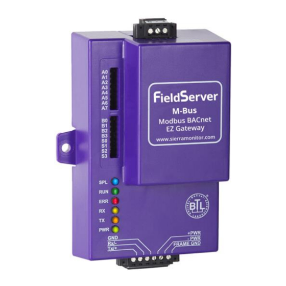
- Page 1 Start-up Guide EZ Gateway M-Bus to Modbus & BACnet FS-EZX-MBUS-MD-BAC APPLICABILITY & EFFECTIVITY Effective for all systems manufactured after January 2021. FS-QS-1011/12X0/12X1/1X50/1X51 Document Revision: 3.A T18604 EZ Gateway Start-up Guide MSAsafety.com...
- Page 2 MSA Safety 1991 Tarob Court Milpitas, CA 95035 Website: www.MSAsafety.com U.S. Support Information: +1 408 964-4443 +1 800 727-4377 Email: smc-support@msasafety.com EMEA Support Information: +31 33 808 0590 Email: smc-support.emea@msasafety.com EZ Gateway Start-up Guide...
-
Page 3: Table Of Contents
Table of Contents About the EZ Gateway ........................7 Supplied Equipment ......................... 7 Certification ..........................7 BTL Mark – BACnet Testing Laboratory .................. 7 1.2.1 Equipment Setup ..........................8 Mounting ........................... 8 Dimension Drawing FS-EZX-MBUS-MD-BAC ................. 9 Installing the EZ Gateway ......................10 M-Bus Connection R2 Port ..................... - Page 4 Additional Information ........................45 Change Web Server Security Settings After Initial Setup ............45 9.1.1 Change Security Mode ......................46 9.1.2 Edit the Certificate Loaded onto the FieldServer ..............47 Change User Management Settings ..................48 9.2.1 Create Users .......................... 49 9.2.2 Edit Users ..........................
- Page 5 List of Figures Figure 1: DIN Rail ............................8 Figure 2: EZ Gateway Dimension Drawing ....................9 Figure 3: M-Bus Connection Port ........................ 10 Figure 4: R1 Port connection ........................10 Figure 5: Bias Resistor DIP Switches & EOL ....................11 Figure 6: Connecting Power........................
- Page 6 Figure 54: FS-GUI User Management ......................48 Figure 55: Create User Window ........................49 Figure 56: Setup Users ..........................50 Figure 57: Edit User Window ........................50 Figure 58: Setup Users ..........................51 Figure 59: User Delete Warning ......................... 51 Figure 60: FieldServer Password Update via FS-GUI ................
-
Page 7: About The Ez Gateway
Check the MSA Safety website for technical support resources and documentation that may be of assistance. The EZ Gateway is cloud ready and connects with MSA Safety’s SMC Cloud. See Section 7.6.1 for further information. -
Page 8: Equipment Setup
FieldServer is removed from the DIN rail, use the original screws to reattach. Only screws supplied by MSA Safety should be used in the holes found on the back of the unit when attaching the optional DIN Rail bracket. USE OF ANY OTHER SCREWS MAY DAMAGE THE UNIT. -
Page 9: Dimension Drawing Fs-Ezx-Mbus-Md-Bac
Equipment Setup Dimension Drawing FS-EZX-MBUS-MD-BAC R1 Port R2 Port Figure 2: EZ Gateway Dimension Drawing EZ Gateway Start-up Guide... -
Page 10: Installing The Ez Gateway
Installation Installing the EZ Gateway M-Bus Connection R2 Port The EZ Gateway M-Bus to Modbus & BACnet is used to transfer data to and from devices using protocols. The M-Bus driver enables data access from M-Bus networks to other FieldServer protocols. Most M-Bus data-point types are supported, allowing communication to almost any kind of M-Bus device in an installation, such as utility meters, energy meters, flow meters, temperature &... -
Page 11: R1 Port Small Dip Switches
Installation R1 Port Small DIP Switches Gently remove the FieldServer enclosure to access the small DIP switches for the R1 Port. Bias Resistor Switch End of Line Switch Figure 5: Bias Resistor DIP Switches & EOL • If more than one RS-485 device is connected to the network, then the field bias resistor switch needs to be enabled to ensure proper communication. -
Page 12: Operation
Operation Operation Power Up the Device Apply power to the device. Ensure that the power supply used complies with the specifications provided. Ensure that the cable is grounded using the “Frame GND” terminal. The EZ Gateway is factory set for 9-30V DC or 12-24V AC. -
Page 13: Connecting To The Ez Gateway
Using the FieldServer Toolbox to Discover and Connect to the EZ Gateway • Install the Toolbox application from the USB drive or download it from the MSA Safety website. • Use the FS Toolbox application to find the EZ Gateway and launch the FS-GUI. -
Page 14: Setup Web Server Security
Setup Web Server Security Setup Web Server Security Login to the FieldServer The first time the FieldServer GUI is opened in a browser, the IP Address for the gateway will appear as untrusted. This will cause the following pop-up windows to appear. •... -
Page 15: Figure 10: Warning Expanded Text
Setup Web Server Security • Additional text will expand below the warning, click the underlined text to go to the IP Address. In Figure 10 example this text is “Proceed to 10.40.50.94 (unsafe)”. Figure 10: Warning Expanded Text • When the login screen appears, put in the Username (default is “admin”) and the Password (found on the label of the FieldServer). -
Page 16: Select The Security Mode
Setup Web Server Security Select the Security Mode On the first login to the FieldServer, the following screen will appear that allows the user to select which mode the FieldServer should use. Figure 12: Security Mode Selection Screen NOTE: Cookies are used for authentication. NOTE: To change the web server security mode after initial setup, go to Section 9.1. -
Page 17: Https With Own Trusted Tls Certificate
Setup Web Server Security 5.2.1 HTTPS with Own Trusted TLS Certificate This is the recommended selection and the most secure. Please contact your IT department to find out if you can obtain a TLS certificate from your company before proceeding with the Own Trusted TLS Certificate option. -
Page 18: Configuring The Ez Gateway
Figure 14) allows users to connect to the SMC Cloud, MSA Safety’s device cloud solution for IIoT. The SMC Cloud enables secure remote connection to field devices through a FieldServer and its local applications for configuration, management, maintenance. For more information about the SMC Cloud,... -
Page 19: M-Bus Settings
Configuring the Gateway Click on the Settings tab (wrench icon) to show all three settings pages: M-Bus, BMS and Network Settings. The table below describes how the buttons at the bottom of each page function. Button Definition Save Click to save settings. Saving will require the device to be restarted. Click to clear the current settings before saving;... -
Page 20: Bms Settings
Configuring the Gateway BMS Settings Select appropriate protocol and enter the fields for the protocol settings described below as needed. 6.2.1 BACnet/IP and BACnet MS/TP Figure 17: BACnet BMS Settings Parameter Definition All Connections The BACnet network number for the connection. Legal values are 1-65534. Each BACnet Network network number must be unique across the entire BACnet internetwork. -
Page 21: Figure 19: Connection Parameters - Bbmd
Configuring the Gateway Enabling BBMD and Editing the Broadcast Distribution Table Parameter Definition BACnet/IP BBMD Settings Enable BBMD Select this checkbox to enable the Router to act as a BBMD. If the BBMD is being accessed across a NAT Router, then these values must be configured with the public IP address and Port by which the BBMD can be reached from across the NAT Router. -
Page 22: Modbus Tcp/Ip And Modbus Rtu
Configuring the Gateway 6.2.2 Modbus TCP/IP and Modbus RTU Figure 21: Connection Settings Parameter Definition All Connections Sets time EZ Gateway will wait for a message frame to complete on the network. This is useful on busy Modbus networks where unknown messages for other Framing Timeout devices may cause longer timeouts. -
Page 23: Network Settings
Configuring the Gateway Network Settings The IP Settings for the EZ Gateway are used by BACnet/IP and Modbus TCP/IP. The IP Settings can be edited in the Network Settings section as shown. Figure 23: IP Settings EZ Gateway Start-up Guide... -
Page 24: Using The Ez Gateway
Using the Gateway Using the EZ Gateway Find Devices Using M-Bus Explorer Page • Click on the M-Bus Explorer tab on the left side of the screen to go to the M-Bus Explorer page. Figure 24: M-Bus Explorer Page • To find M-Bus devices connected to the same subnet as the EZ Gateway, click the Discover button (binoculars icon). -
Page 25: Figure 26: M-Bus Explorer Page With Discovered Devices
Using the Gateway Discovery Types There are two discovery types that are useful in different situations. See details below. Secondary Address – This discovery type should be used when there are multiple devices connected to the bus to do a wildcard search across the full address space. However, only some M-Bus Slave devices support secondary address discovery. -
Page 26: Figure 27: Device Information
Using the Gateway Device Status There are four possible statuses for a device as seen in parenthesis in Figure No Profile – The EZ Gateway does not have a profile for this device. Not Loaded – The EZ Gateway has a saved profile for this device but the profile instance is not loaded. Loaded –... -
Page 27: Create A Profile From A Discovered Device
Using the Gateway Create a Profile from a Discovered Device • Click on the desired device to show Configuration Status, Details and Data. Compatible Profile Exists – If “True” is displayed, a profile already exists for this M-Bus discovered device. Profile Instance Loaded –... -
Page 28: Figure 29: New Profile - Select Profile Settings
Using the Gateway • Define the Profile Settings as needed. Figure 29: New Profile – Select Profile Settings NOTE: A profile baud rate can be set to global or a specific buad rate. To set the global buad rate see Section 6.1. •... -
Page 29: Figure 31: New Profile - Adding Notification Class
Using the Gateway • Add Notification Class(es) if needed. Click the Add button and enter the number of Notification Classes to create Fill in the fields as needed NOTE: The desired notification class must be specified per point on the data map. NOTE: The Save button will be disabled unless all red fields are filled in with valid values. -
Page 30: Figure 33: Save Profile Window
Using the Gateway • Once all editing is complete, click the Save button to open the Save Profile window; name the profile and click Save again to complete profile creation. Figure 33: Save Profile Window • After saving the profile the following messages will appear: •... -
Page 31: Manage Profiles Using The Device Profiles Page
Using the Gateway Manage Profiles Using the Device Profiles Page • Click on the Device Profiles tab on the left side of the screen to go to the device profiles page. Figure 34: Device Profiles Page NOTE: If a profile has been saved from a discovered device using the M-Bus Explorer, the saved profiles will appear on this page. -
Page 32: Edit Button
Using the Gateway 7.3.2 Edit Button • Through the Edit button the Profile Settings, Data Map, Notification Classes and State Table can be redefined. NOTE: See Section for a walkthrough on editing profile information. Figure 36: Edit Profile Window • Once all editing is complete, click the Save button to open the Save Profile window;... -
Page 33: Delete Button
Using the Gateway 7.3.3 Delete Button • Click the Delete button to remove the profile in that row from the EZ Gateway. Figure 38: Device Profiles Page – Delete Button 7.3.4 Export Button • Click the Export button to create a copy of the profile in that row on the local computer’s default download folder. -
Page 34: Load A Profile Instance Using M-Bus Explorer
Using the Gateway Load a Profile Instance Using M-Bus Explorer • Click the M-Bus Explorer tab. • Click on a device to load that also has a profile saved on the EZ Gateway (the Compatible Profile Exists parameter is “True”). •... -
Page 35: Figure 42: Load Profile Instance Window
Using the Gateway • The associated BACnet and M-Bus parameters will populate from the profile saved on the EZ Gateway. Figure 42: Load Profile Instance Window • Edit and enter additional parameter information as needed. • Click Save and then click Restart when prompted to load the new settings. EZ Gateway Start-up Guide... -
Page 36: View Live Data Using Live View
Using the Gateway View Live Data Using Live View • Click on the Live View tab on the left side of the screen to go to the Live View page. The Live View page will now show the created profile instance Figure 43: Live View Page with Created Profile Instance •... -
Page 37: Figure 45: Viewing Created Profile Instance Settings
Using the Gateway Settings – Profile Instance, M-Bus Parameters and BACnet Parameters Figure 45: Viewing Created Profile Instance Settings NOTE: To export the EDE file, click the Export EDE button (Figure 45) and fill out the Export EDE window as needed. Figure 46: Export EDE Window EZ Gateway Start-up Guide... -
Page 38: Ez Gateway Diagnostics And Cloud Connection
Figure 47) allows users to connect to the SMC Cloud, MSA Safety’s device cloud solution for IIoT. The SMC Cloud enables secure remote connection to field devices through a FieldServer and its local applications for configuration, management, maintenance. For more information about the SMC Cloud,... -
Page 39: Troubleshooting
Troubleshooting Troubleshooting Communicating with the EZ Gateway Over the Network • Confirm that the network cabling is correct. • Confirm that the computer network card is operational and correctly configured. • Confirm that there is an Ethernet adapter installed in the PC’s Device Manager List, and that it is configured to run the TCP/IP protocol. -
Page 40: Taking A Fieldserver Diagnostic Capture
Troubleshooting Taking a FieldServer Diagnostic Capture When there is a problem on-site that cannot easily be resolved, perform a Diagnostic Capture before contacting support. Once the Diagnostic Capture is complete, email it to technical support. The Diagnostic Capture will accelerate diagnosis of the problem. If the FieldServer bios is updated/released on November 2017 or later then the Diagnostic Capture is performed via the gateway’s on-board system. -
Page 41: Taking A Capture With Older Firmware
Newer versions may be available on the MSA Safety website. • Ensure that FieldServer Toolbox is loaded onto the local PC. Otherwise, download the FieldServer-Toolbox.zip via the MSA Safety website. • Extract the executable file and complete the installation. Ethernet Port Figure 48: Ethernet Port Location •... - Page 42 Troubleshooting Select “Full Diagnostic" from the drop down menu NOTE: If desired, the default capture period can be changed. Click on the Start Diagnostic button Wait for the capture period to finish and the Diagnostic Test Complete window will appear •...
-
Page 43: Notes Regarding Subnets And Subnet Masks
Troubleshooting Notes Regarding Subnets and Subnet Masks RFC standards allocate the IP Address range of 192.0.0.0 through to 223.255.255.255 to be used in Class- C subnetting (subnets listed as 255.255.255.xxx, where xxx can vary based on filtering required). Consequently, the IP stack for this product will not allow any IP Addresses in this range to be allocated a subnet that does not fall within the Class C range. -
Page 44: Internet Browser Software Support
Troubleshooting Internet Browser Software Support The following web browsers are supported: • Chrome Rev. 57 and higher • Firefox Rev. 35 and higher • Microsoft Edge Rev. 41 and higher • Safari Rev. 3 and higher NOTE: Internet Explorer is no longer supported as recommended by Microsoft. NOTE: Computer and network firewalls must be opened for Port 80 to allow FieldServer GUI to function. -
Page 45: Additional Information
Additional Information Additional Information Change Web Server Security Settings After Initial Setup NOTE: Any changes will require a FieldServer reboot to take effect. • Navigate from the EZ Gateway landing page to the FS-GUI by clicking the blue “Diagnostics” text on the bottom of the screen. -
Page 46: Change Security Mode
Additional Information 9.1.1 Change Security Mode • Click Security in the Navigation panel. Figure 52: FS-GUI Security Setup • Click the Mode desired. If HTTPS with own trusted TLS certificate is selected, follow instructions in Section 5.2.1 • Click the Save button. EZ Gateway Start-up Guide... -
Page 47: Edit The Certificate Loaded Onto The Fieldserver
Additional Information 9.1.2 Edit the Certificate Loaded onto the FieldServer NOTE: A loaded certificate will only be available if the security mode was previously setup as HTTPS with own trusted TLS certificate. • Click Security in the Navigation panel. Figure 53: FS-GUI Security Setup – Certificate Loaded •... -
Page 48: Change User Management Settings
Additional Information Change User Management Settings • From the FS-GUI page, click Setup in the Navigation panel. • Click User Management in the navigation panel. NOTE: If the passwords are lost, the unit can be reset to factory settings to reinstate the default unique password on the label. -
Page 49: Create Users
Additional Information 9.2.1 Create Users • Click the Create User button. Figure 55: Create User Window • Enter the new User fields: Name, Security Group and Password. User details are hashed and salted NOTE: The password must meet the minimum complexity requirements. An algorithm automatically checks the password entered and notes the level of strength on the top right of the Password text field. -
Page 50: Edit Users
Additional Information 9.2.2 Edit Users • Click the pencil icon next to the desired user to open the User Edit window. Figure 56: Setup Users • Once the User Edit window opens, change the User Security Group and Password as needed. Figure 57: Edit User Window •... -
Page 51: Delete Users
Additional Information 9.2.3 Delete Users • Click the trash can icon next to the desired user to delete the entry. Figure 58: Setup Users • When the warning message appears, click Confirm. Figure 59: User Delete Warning EZ Gateway Start-up Guide... -
Page 52: Change Fieldserver Password
Additional Information 9.2.4 Change FieldServer Password • Click the Password tab. Figure 60: FieldServer Password Update via FS-GUI • Change the general login password for the FieldServer as needed. NOTE: The password must meet the minimum complexity requirements. An algorithm automatically checks the password entered and notes the level of strength on the top right of the Password text field. -
Page 53: Specifications
Additional Information Specifications FS-EZX-MBUS-MD-BAC One 6-pin Phoenix connector with: M-Bus port (+ / - / No Connection) Power port (+ / - / Frame-gnd) Electrical Connections One 3-pin Phoenix connector with: RS-485 port (+ / - / gnd) One Ethernet 10/100 BaseT port Input Voltage: 9-24VDC or 12-24VAC Power Requirements Max Power: 12 Watts... -
Page 54: Compliance With Ul Regulations
Additional Information Compliance with UL Regulations For UL compliance, the following instructions must be met when operating EZ Gateway. • The units shall be powered by listed LPS or Class 2 power supply suited to the expected operating temperature range. •... -
Page 55: 10 Limited 2 Year Warranty
MSA Safety warrants its products to be free from defects in workmanship or material under normal use and service for two years after date of shipment. MSA Safety will repair or replace any equipment found to be defective during the warranty period. Final determination of the nature and responsibility for defective or damaged equipment will be made by MSA Safety personnel.
Need help?
Do you have a question about the fieldserver EZ Gateway M-Bus to Modbus & BACnet and is the answer not in the manual?
Questions and answers