
Related Manuals for MSA fieldserver ProtoAir FPA-C41


Summary of Contents for MSA fieldserver ProtoAir FPA-C41
- Page 1 Operating Manual ProtoAir Start-up Guide FPA-W44, FPA-C41, FPA-C42, FPA-C43 Revision: 3.N Document No.: T18622 Print Spec: 10000005389 (F) MSAsafety.com...
- Page 2 1000 Cranberry Woods Drive +1 408 964-4443 +31 33 808 0590 Cranberry Township, PA 16066 USA +1 800 727-4377 Email: smc-support.emea@msasafety.com Email: smc-support@msasafety.com For your local MSA contacts, please go to our website www.MSAsafety.com © MSA 2023. All rights reserved...
-
Page 3: Table Of Contents
Contents About the ProtoAir Equipment Setup Mounting Attaching the Antenna(s) Physical Dimensions 2.3.1 FPA-W44 Drawing 2.3.2 FPA-C4X Drawing Installation DIP Switch Settings for FPA-C4X 3.1.1 Bias Resistors 3.1.2 Termination Resistor DIP Switch Settings for FPA-W44 3.2.1 Bias Resistors 3.2.2 Termination Resistor FPA-C4X: Inserting the SIM Card FPA-C4X: Connecting the P1 Port 3.4.1 Wiring... - Page 4 10.1 Connecting to the Network Through Wi-Fi 10.2 Connecting to Devices via Access Point 10.3 Device Communications via Wi-Fi 10.4 Connecting Devices to the Network Troubleshooting 11.1 Communicating with the ProtoAir Over the Network 11.2 Lost or Incorrect IP Address 11.3 Viewing Diagnostic Information 11.4...
-
Page 5: About The Protoair
NOTE: For troubleshooting assistance refer to Section Troubleshooting, or any of the troubleshooting appendices in the related driver supplements. Check the MSA Safety website for technical support resources and documentation that may be of assistance. The ProtoAir is cloud ready and connects with MSA Safety’s Grid. See Section 9.4.1 Accessing the FieldServer... -
Page 6: Equipment Setup
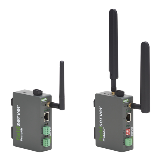
2 Equipment Setup Equipment Setup Mounting The gateway can be mounted using the DIN rail mounting bracket on the back of the unit. Attaching the Antenna(s) Wi-Fi Antenna: If using the FPA-W44 model, screw in the Wi-Fi antenna to the front of the unit as shown in Section 2.3.1 FPA-W44 Drawing. -
Page 7: Physical Dimensions
2 Equipment Setup Physical Dimensions 2.3.1 FPA-W44 Drawing ProtoAir Start-up Guide... -
Page 8: Fpa-C4X Drawing
2 Equipment Setup 2.3.2 FPA-C4X Drawing ProtoAir Start-up Guide... -
Page 9: Installation
3 Installation Installation DIP Switch Settings for FPA-C4X 3.1.1 Bias Resistors To enable Bias Resistors, move both the BIAS- and BIAS+ dip switches to the right in the orientation shown above. The bias resistors are used to keep the RS-485 bus to a known state, when there is no transmission on the line (bus is idling), to help prevent false bits of data from being detected. -
Page 10: Termination Resistor
3 Installation 3.1.2 Termination Resistor If the gateway is the last device on the serial trunk, then the End-Of-Line Termination Switch needs to be enabled. To enable the Termination Resistor, move the TERM dip switch to the right in the orientation shown in above. Termination resistor is also used to reduce noise. -
Page 11: Dip Switch Settings For Fpa-W44
3 Installation DIP Switch Settings for FPA-W44 3.2.1 Bias Resistors To enable Bias Resistors, move both the BIAS- and BIAS+ DIP switches to the right in the orientation shown above. The bias resistors are used to keep the RS-485 bus to a known state, when there is no transmission on the line (bus is idling), to help prevent false bits of data from being detected. -
Page 12: Termination Resistor
3 Installation 3.2.2 Termination Resistor If the gateway is the last device on the serial trunk, then the End-Of-Line Termination Switch needs to be enabled. To enable the termination resistor, move the TERM dip switch to the right in the orientation shown in above. The termination resistor is also used to reduce noise. -
Page 13: Fpa-C4X: Inserting The Sim Card
3 Installation FPA-C4X: Inserting the SIM Card NOTE: A micro 4G SIM card must be purchased from an AT&T or Verizon cellular provider to set up cellular functionality and create a data plan for the FieldServer. SIM card vendor contact information is available at the end of the section. - Page 14 3 Installation SIM Card Vendor Contact Information: Verizon A business contract is required to purchase a Verizon SIM card. The IMEI of the ProtoAir is required to purchase the Verizon SIM card. AT&T Please call AT&T Customer Service at 800.331.0500 or find the nearest AT&T store. ProtoAir Start-up Guide...
-
Page 15: Fpa-C4X: Connecting The P1 Port
3 Installation FPA-C4X: Connecting the P1 Port Switch between RS-485 and RS-232 by moving the number 4 DIP Switch left for RS-485 and right for RS-232. Connect to the 3-pin connector as shown below. The following baud rates are supported on the P1 Port: 9600, 19200, 38400, 57600, 76800, 115000 NOTE: Not all baud rates listed are supported by all protocols. -
Page 16: Fpa-W44: Connecting The R1 & R2 Ports
3 Installation FPA-W44: Connecting the R1 & R2 Ports For the R1 Port only: Switch between RS-485 and RS-232 by moving the number 4 DIP Switch left for RS-485 and right for RS-232 (see images in Section 3.2 DIP Switch Settings for FPA-W44). -
Page 17: Power Up The Gateway
4 Power up the Gateway Power up the Gateway Check power requirements in the table below: Power Requirement for ProtoAir External Gateway Current Draw Type ProtoAir Family 12VDC 24VDC/AC FPA –W44 (Typical) 250mA 125mA ProtoAir Family 12VDC 24VDC FPA –C4X (Typical) 320mA 185mA FPA –C4X (Maximum) -
Page 18: Connect The Pc To The Gateway
5 Connect the PC to the Gateway Connect the PC to the Gateway 10/100 Ethernet Connection Port NOTE: Do not use shielded Ethernet cables. The Ethernet Port is used both for Ethernet protocol communications and for configuring the gateway via the Web App. To connect the gateway, either connect the PC to the router’s Ethernet port or connect the router and PC to an Ethernet switch. -
Page 19: Connecting To The Protoair
Using the FieldServer Toolbox to Discover and Connect to the ProtoAir • Install the Toolbox application from the USB drive or download it from the MSA Safety website. • Use the FS Toolbox application to find the ProtoAir and connect to the ProtoAir. -
Page 20: Setup Web Server Security
7 Setup Web Server Security Setup Web Server Security Login to the FieldServer The first time the FieldServer GUI is opened in a browser, the IP Address for the gateway will appear as untrusted. This will cause the following pop-up windows to appear. •... - Page 21 7 Setup Web Server Security • Additional text will expand below the warning, click the underlined text to go to the IP Address. In the example below this text is “Proceed to <FieldServer IP> (unsafe)”. • When the login screen appears, put in the Username (default is “admin”) and the Password (found on the label of the FieldServer).
-
Page 22: Select The Security Mode
7 Setup Web Server Security Select the Security Mode On the first login to the FieldServer, the following screen will appear that allows the user to select which mode the FieldServer should use. NOTE: Cookies are used for authentication. NOTE: To change the web server security mode after initial setup, go to Section 12.1 Change Web Server Security Settings After Initial Setup. -
Page 23: Https With Own Trusted Tls Certificate
7 Setup Web Server Security 7.2.1 HTTPS with Own Trusted TLS Certificate This is the recommended selection and the most secure. Please contact your IT department to find out if you can obtain a TLS certificate from your company before proceeding with the Own Trusted TLS Certificate option. •... -
Page 24: Setup Network
8 Setup Network Setup Network Using FS-GUI to Input Network Settings To navigate from the FS-GUI page to the Network Settings page follow the below instructions: • Find the Navigation tree across the left side of the screen. • Click the arrow next to the FieldServer title/CN number to expand the tree. •... -
Page 25: Ethernet
8 Setup Network 8.1.1 Ethernet 1 The ETH 1 section contains the wired network settings. To change the FieldServer IP Settings, follow these instructions: • Enable DHCP to automatically assign IP Settings or modify the IP Settings manually as needed, via these fields: IP Address, Netmask, Default Gateway, and Domain Name Server1/2. -
Page 26: Wi-Fi Client Settings
8 Setup Network 8.1.2 Wi-Fi Client Settings • Set the Wi-Fi Status to ENABLED for the ProtoAir to communicate with other devices via Wi-Fi. • Enter the Wi-Fi SSID and Wi-Fi Password for the local wireless access point. • Enable DHCP to automatically assign all Wi-Fi Client Settings fields or modify the Settings manually, via the fields immediately below the note (IP Address, Network, etc.). -
Page 27: Wi-Fi Access Point Settings
8 Setup Network 8.1.3 Wi-Fi Access Point Settings • Check the Enable tick box to allow connecting to the ProtoAir via Wi-Fi Access Point. • Modify the Settings manually as needed, via these fields: SSID, Password, Channel, IP Address, Netmask, IP Pool Address Start, and IP Pool Address End. -
Page 28: Routing Settings
8 Setup Network 8.1.4 Routing Settings The Routing settings make it possible to set up the IP routing rules for the FieldServer’s internet and network connections. NOTE: The default connection is ETH1. • Select the default connection in the first row. •... -
Page 29: Fpa-C4X: Cellular Settings
8 Setup Network 8.1.5 FPA-C4X: Cellular Settings To change the Cellular settings, follow these instructions: • Check the Enable tick box to allow connecting to the ProtoAir through the Grid. • Modify the Settings manually as needed, via these fields: Cellular APN (see Section 12.4 APN Table), User Name, and Password. -
Page 30: Configuring The Protoair
9 Configuring the ProtoAir Configuring the ProtoAir Retrieve the Sample Configuration File The configuration of the ProtoAir is provided to the ProtoAir’s operating system via a comma-delimited file called “CONFIG.CSV”. If a custom configuration was ordered, the ProtoAir will be programmed with the relevant device registers in the Config.csv file for the initial start-up. -
Page 31: Load The Updated Configuration File
9 Configuring the ProtoAir Load the Updated Configuration File 9.3.1 Using the FS-GUI to Load a Configuration File • In the main menu of the FS-GUI screen, click “Setup”, then “File Transfer” and finally “Update”. • Browse and select the .csv file, open, then click “Submit”. •... -
Page 32: Retrieve The Configuration File For Modification Or Backup
9 Configuring the ProtoAir 9.3.2 Retrieve the Configuration File for Modification or Backup To get a copy of the configuration file for modifying or backing up a configuration on a local computer, do the following: • In the main menu of the FS-GUI screen, click “Setup”, then “File Transfer”. •... -
Page 33: Test And Commission The Protoair
NOTE: For troubleshooting assistance refer to Section Troubleshooting, or any of the troubleshooting appendices in the related driver supplements and configuration manual. MSA Safety also offers a technical support on the MSA Safety website, which contains a significant number of resources and documentation that may be of assistance. -
Page 34: Applications
10 Applications Applications 10.1 Connecting to the Network Through Wi-Fi The ProtoAir can connect customer devices to the local Ethernet Network via Wi-Fi signal and connect customer devices to the cloud via cellular for remote accessibility. ProtoAir Start-up Guide... -
Page 35: Connecting To Devices Via Access Point
10 Applications 10.2 Connecting to Devices via Access Point Customer devices setup on the ProtoAir can be connected to via the ProtoAir’s dedicated Access Point. ProtoAir Start-up Guide... -
Page 36: Device Communications Via Wi-Fi
10 Applications 10.3 Device Communications via Wi-Fi The ProtoAir can connect multiple customer devices via Wi-Fi. ProtoAir Start-up Guide... -
Page 37: Connecting Devices To The Network
10 Applications 10.4 Connecting Devices to the Network The ProtoAir can connect devices to the local Network via Wi-Fi. ProtoAir Start-up Guide... -
Page 38: Troubleshooting
11 Troubleshooting Troubleshooting 11.1 Communicating with the ProtoAir Over the Network • Confirm that the network cabling is correct. • Confirm that the computer network card is operational and correctly configured. • Confirm that there is an Ethernet adapter installed in the PC’s Device Manager List, and that it is configured to run the TCP/IP protocol. -
Page 39: Lost Or Incorrect Ip Address
11.2 Lost or Incorrect IP Address • Ensure that FieldServer Toolbox is loaded onto the local PC. Otherwise, download the FieldServer-Toolbox.zip via the MSA Safety website. • Extract the executable file and complete the installation. • Connect a standard Cat-5 Ethernet cable between the user’s PC and ProtoAir. -
Page 40: Viewing Diagnostic Information
11 Troubleshooting 11.3 Viewing Diagnostic Information • Type the IP Address of the FieldServer into the web browser or use the FieldServer Toolbox to connect to the FieldServer. • Click on Diagnostics and Debugging Button, then click on view, and then on connections. •... -
Page 41: Checking Wiring And Settings
11 Troubleshooting 11.4 Checking Wiring and Settings No COMS on the Serial side. If the Tx/Rx LEDs are not flashing rapidly then there is a COM issue. To fix this problem, check the following: • Visual observations of LEDs on the ProtoAir. (Section 11.6 LED Functions) •... -
Page 42: Taking A Fieldserver Diagnostic Capture
11 Troubleshooting 11.5 Taking a FieldServer Diagnostic Capture When there is a problem on-site that cannot easily be resolved, perform a Diagnostic Capture before contacting support. Once the Diagnostic Capture is complete, email it to technical support. The Diagnostic Capture will accelerate diagnosis of the problem. -
Page 43: Led Functions
11 Troubleshooting 11.6 LED Functions Description The SS LED will flash once a second to indicate that the bridge is in operation. The SYS ERR LED will go on solid indicating there is a system error. If this occurs, immediately report the related “system error”... -
Page 44: Factory Reset Instructions
11 Troubleshooting 11.7 Factory Reset Instructions For instructions on how to reset a FieldServer back to its factory released state, see ENOTE FieldServer Next Gen Recovery. 11.8 Internet Browser Software Support The following web browsers are supported: • Chrome Rev. 57 and higher •... -
Page 45: Additional Information
12 Additional Information Additional Information 12.1 Change Web Server Security Settings After Initial Setup NOTE: Any changes will require a FieldServer reboot to take effect. • Navigate to the FS-GUI page. • Click Setup in the Navigation panel. ProtoAir Start-up Guide... -
Page 46: Change Security Mode
12 Additional Information 12.1.1Change Security Mode • Click Security in the Navigation panel. • Click the Mode desired. ◦ If HTTPS with own trusted TLS certificate is selected, follow instructions in Section 7.2.1 HTTPS with Own Trusted TLS Certificate • Click the Save button. ProtoAir Start-up Guide... -
Page 47: Edit The Certificate Loaded Onto The Fieldserver
12 Additional Information 12.1.2Edit the Certificate Loaded onto the FieldServer NOTE: A loaded certificate will only be available if the security mode was previously setup as HTTPS with own trusted TLS certificate. • Click Security in the Navigation panel. • Click the Edit Certificate button to open the certificate and key fields. •... -
Page 48: Change User Management Settings
12 Additional Information 12.2 Change User Management Settings • From the FS-GUI page, click Setup in the Navigation panel. • Click User Management in the navigation panel. NOTE: If the passwords are lost, the unit can be reset to factory settings to reinstate the default unique password on the label. -
Page 49: Create Users
12 Additional Information 12.2.1Create Users • Click the Create User button. • Enter the new User fields: Name, Security Group and Password. ◦ User details are hashed and salted NOTE: The password must meet the minimum complexity requirements. An algorithm automatically checks the password entered and notes the level of strength on the top right of the Password text field. -
Page 50: Edit Users
12 Additional Information 12.2.2Edit Users • Click the pencil icon next to the desired user to open the User Edit window. • Once the User Edit window opens, change the User Security Group and Password as needed. • Click Confirm. •... -
Page 51: Delete Users
12 Additional Information 12.2.3Delete Users • Click the trash can icon next to the desired user to delete the entry. • When the warning message appears, click Confirm. ProtoAir Start-up Guide... -
Page 52: Change Fieldserver Password
12 Additional Information 12.2.4Change FieldServer Password • Click the Password tab. • Change the general login password for the FieldServer as needed. NOTE: The password must meet the minimum complexity requirements. An algorithm automatically checks the password entered and notes the level of strength on the top right of the Password text field. ProtoAir Start-up Guide... -
Page 53: Update Firmware
12 Additional Information 12.3 Update Firmware To load a new version of the firmware, follow these instructions: 1. Extract and save the new file onto the local PC. 2. Open a web browser and type the IP Address of the FieldServer in the address bar. ◦... -
Page 54: Kaspersky Endpoint Security
12 Additional Information 12.6 Kaspersky Endpoint Security 10 If Kaspersky Endpoint Security 10 is installed on the user’s PC, the software needs to be modified to allow the PC to register bridges on the FieldServer Manager. NOTE: This problem is specific to KES10, Kaspersky 2017 does not have this problem. To fix the problem, the ProtoAir (see http://192.168.100.85/* in the 2 image below) must be set as a trusted URL to the "Web Anti-Virus"->"Settings"... -
Page 55: Specifications
12 Additional Information 12.7 Specifications ProtoAir FPA-W44 & FPA-C4X One 3-pin Phoenix connector with: RS-485/RS-232 (Tx+ / Rx- / gnd) One 3-pin Phoenix connector with: Power port (+ / - / Frame-gnd) Electrical Connections One Ethernet 10/100 BaseT port W44 includes an additional: One 3-pin Phoenix connector with: RS-485 (+ / - / gnd) Input Voltage: 12-24VDC or 24VAC Current draw: 24VAC 0.125A W44 Power Requirements... -
Page 56: Warnings For Fcc And Ic
12 Additional Information 12.9 Warnings for FCC and IC Waste Disposal It is recommended to disassemble the device before abandoning it in conformity with local regulations. Please ensure that the abandoned batteries are disposed according to local regulations on waste disposal. Do not throw batteries into fire (explosive) or put in common waste canister. - Page 57 • Consult the dealer or an experienced radio/TV technician for help. Any modification to the product is not permitted unless authorized by MSA Safety. It’s not allowed to disassemble the product; it is not allowed to replace the system or change components unless with permission and certification. Please contact the FieldServer technical support department or local branches for help.
- Page 58 End-users and installers must be provided with antenna installation instructions and transmitter operating conditions for satisfying RF exposure compliance. For product compliance test FCC and IC, all the technical documentation is submitted by MSA Safety, who is the customer or importer of the ProtoAir.
-
Page 59: Limited 2 Year Warranty
Limited 2 Year Warranty MSA Safety warrants its products to be free from defects in workmanship or material under normal use and service for two years after date of shipment. MSA Safety will repair or replace any equipment found to be defective during the warranty period.
Need help?
Do you have a question about the fieldserver ProtoAir FPA-C41 and is the answer not in the manual?
Questions and answers