MSA fieldserver ProtoAir FPA-W44 Operating Manual
Hide thumbs
Also See for fieldserver ProtoAir FPA-W44:
- Operating manual (79 pages) ,
- Startup manual (65 pages) ,
- Operating manual (69 pages)

Subscribe to Our Youtube Channel
Related Manuals for MSA fieldserver ProtoAir FPA-W44


Summary of Contents for MSA fieldserver ProtoAir FPA-W44
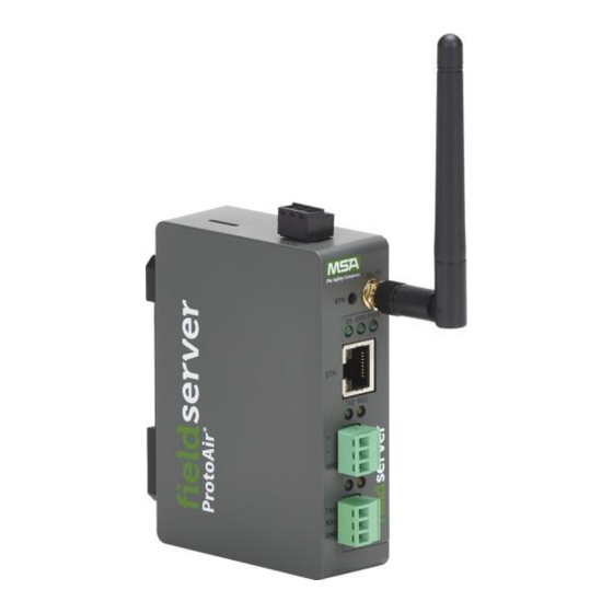
- Page 1 Operating Manual ProtoAir FPA-W44 for Interfacing Bryan Steam & Thermal Solutions Products Revision: 13 Document No.:106417-02 Print Spec: 10000005389 (F) MSAsafety.com...
- Page 2 EMEA Support Information: 1991 Tarob Court +1 408 964-4443 +31 33 808 0590 Milpitas, CA 95035 +1 800 727-4377 Email: smc-support.emea@msasafety.com Email: smc-support@msasafety.com For your local MSA contacts, please go to our website www.MSAsafety.com © MSA 2021. All rights reserved...
- Page 3 Thank you for purchasing the ProtoAir for Bryan Steam & Thermal Solutions. Please call Bryan Steam or Thermal Solutions for technical support of the ProtoAir product. MSA Safety does not provide direct support. If B.S. or T.S. needs to escalate the concern, they will contact MSA Safety for assistance.
- Page 4 Quick Start Guide 1. Methods of Configuration: (Section 1.2 Methods of Configuration) • Auto-Discovery: See the table of devices that support automatic configuration. • Web Configurator: For devices that cannot be automatically configured, use a web browser to access the Web Configurator page.
-
Page 5: Table Of Contents
7.2.2 Ethernet 1 _______________________________________________________________________________________ 26 7.2.3 Wi-Fi Client Settings ______________________________________________________________________________ 27 7.2.4 Wi-Fi Access Point Settings ________________________________________________________________________ 28 MSA Grid - FieldSever Manager Setup ____________________________________________________________________29 Choose Whether to Integrate the FieldServer Manager _________________________________________________ 29 User Setup ______________________________________________________________________________________ 30 Registration Process ______________________________________________________________________________ 32... - Page 6 Configure the ProtoAir _________________________________________________________________________________ 38 Navigate to the ProtoAir Web Configurator ____________________________________________________________ 38 Select Field Protocol and Set Configuration Parameters ________________________________________________ 39 Configure Devices Connected to the Gateway ________________________________________________________ 40 9.3.1 Use Discovery Mode ______________________________________________________________________________ 40 9.3.2 Setting Active Profiles _____________________________________________________________________________ 41 Verify Device Communications ______________________________________________________________________42 BACnet: Setting Node_Offset to Assign Specific Device Instances _______________________________________ 43 How to Start the Installation Over: Clearing Profiles ____________________________________________________ 44...
-
Page 7: Introduction
FPA-W44 Connectivity Diagram: The ProtoAir can connect with the MSA Grid – FieldServer Manager. The FieldServer Manager allows technicians, the OEM's support team and MSA Safety's support team to remotely connect to the ProtoAir. The FieldServer Manager provides the following capabilities for any registered devices in the field: •... -
Page 8: Methods Of Configuration
Methods of Configuration The ProtoAir offers two methods of configuration: • Auto-Discovery: Supported RS-485 devices can be automatically detected and identified for addition to the ProtoAir’s configuration via the ProtoAir’s Web Configurator. (Section 9.3.1 Use Discovery Mode) • Web Configurator: Devices that cannot be identified by Auto-Discovery must be configured to the gateway by selecting profiles on the ProtoAir’s Web Configurator. -
Page 9: Setup For Protoair
Setup for ProtoAir Record Identification Data Each ProtoAir has a unique part number located on the side or the back of the unit. This number should be recorded, as it may be required for technical support. The numbers are as follows: Model Part Number ProtoAir FPA-W44-1744... -
Page 10: Configuring Device Communications
Configuring Device Communications 2.3.1 Confirm the Device and ProtoAir COM Settings Match • Any connected serial devices MUST have the same baud rate, data bits, stop bits, and parity settings as the ProtoAir. • The table below specifies the device serial port settings required to communicate with the ProtoAir. Sola, 4109, TSBC, Port Setting Other Devices... -
Page 11: Interfacing Protoair To Devices
Interfacing ProtoAir to Devices Device Connections to ProtoAir The ProtoAir has a 3-pin Phoenix connector for connecting RS-485 devices on the R1 port. NOTE: Use standard grounding principles for RS-485 GND. Bryan Steam ProtoAir Start-up Guide... -
Page 12: Wiring The Sola To The Protoair Without Display - Single Sola Controller
3.1.1 Wiring the Sola to the ProtoAir without Display – Single Sola Controller • Connect MB2’s terminal A (RS-485+) to Pin 1 (RS-485+) on the ProtoAir 3-pin Phoenix connector. • Connect MB2’s terminal B (RS-485-) to Pin 2 (RS-485-) on the ProtoAir 3-pin Phoenix connector. •... - Page 13 3.1.2 Wiring the Sola to the ProtoAir on Apex & AMP/BFIT 400-1000L with Concert Display • There are two options for wiring the ProtoAir to an Apex or AMP/BFIT 400-1000L with Concert Display: ◦ Connect one end of an RJ45 cable to the boiler PCB and cut off the other end of the cable to access the individual wires of the RJ45 cable.
- Page 14 3.1.4 Wiring the Sola to the ProtoAir on Arctic/FreeFlex 1500-6000 & AMP/BFIT 1000-4000 • Arctic/FreeFlex & AMP/BFIT 1000-4000 with Concert Displays are able to do both Lead Lag (Sequencer) and EMS communication at the same time. • These boilers are equipped with a wire harness which connects the Sola, Communications Board (PCB-06), and ProtoAir. ProtoAir Harness EMS BACnet...
-
Page 15: Wiring Rm7800 Series To The Protoair
3.1.6 Wiring RM7800 Series to the ProtoAir • On the RM7800 Series; connect terminal A (RS-485+) to Pin 1 (RS-485+) on the ProtoAir 3-pin Phoenix connector. • Connect terminal CB RxD / TxD- (RS-485-) to Pin 2 (RS-485-) on the ProtoAir 3-pin Phoenix connector. •... - Page 16 3.1.7 Wiring TSBC to the ProtoAir • The Modbus communication connects to the same RJ11 port that is used by the boiler-to-boiler communication. • Connect one end of the RJ11 cable to the TSBC and cut off the other end of the cable to access the individual wires of the RJ11 cable.
-
Page 17: Wiring Field Port To Rs-485 Serial Network
Wiring Field Port to RS-485 Serial Network • Connect the RS-485 network wires to the 3-pin RS-485 connector on the R2 port. ◦ Use standard grounding principles for RS-485 GND • See Section 5.1 Connecting to the Gateway via Ethernet for information on connecting to an Ethernet network. -
Page 18: Bias Resistors
3.2.1 Bias Resistors To enable Bias Resistors, move both the BIAS- and BIAS+ dip switches to the right in the orientation shown above. The bias resistors are used to keep the RS-485 bus to a known state, when there is no transmission on the line (bus is idling), to help prevent false bits of data from being detected. -
Page 19: Termination Resistor
3.2.2 Termination Resistor If the gateway is the last device on the serial trunk, then the End-Of-Line Termination Switch needs to be enabled. To enable the Termination Resistor, move the TERM dip switch to the right in the orientation shown in above. Termination resistor is also used to reduce noise. -
Page 20: Power Up The Gateway
Power up the Gateway Check power requirements in the table below: Power Requirement for ProtoAir External Gateway Current Draw Type ProtoAir Family 12VDC 24VDC/AC FPA –W44 (Typical) 250mA 125mA NOTE: These values are ‘nominal’ and a safety margin should be added to the power supply of the host system. A safety margin of 25% is recommended. -
Page 21: Connect The Pc To The Gateway
Connect the PC to the Gateway Connecting to the Gateway via Ethernet Connect a Cat-5 Ethernet cable (straight through or cross-over) between the local PC and ProtoAir . 5.1.1 Changing the Subnet of the Connected PC The default IP Address for the ProtoAir is 192.168.1.24, Subnet Mask is 255.255.255.0. If the PC and ProtoAir are on different IP networks, assign a static IP Address to the PC on the 192.168.1.xxx network. -
Page 22: Setup Web Server Security
Setup Web Server Security Login to the FieldServer The first time the FieldServer GUI is opened in a browser, the IP Address for the gateway will appear as untrusted. This will cause the following pop-up windows to appear. • When the Web Server Security Unconfigured window appears, read the text and choose whether to move forward with HTTPS or HTTP. - Page 23 • Additional text will expand below the warning, click the underlined text to go to the IP Address. In the example below this text is “Proceed to 10.40.50.94 (unsafe)”. • When the login screen appears, put in the Username (default is “admin”) and the Password (found on the label of the FieldServer).
-
Page 24: Select The Security Mode
Select the Security Mode On the first login to the FieldServer, the following screen will appear that allows the user to select which mode the FieldServer should use. NOTE: Cookies are used for authentication. NOTE: To change the web server security mode after initial setup, go to Section 11.6 Change Web Server Security Settings After Initial Setup. -
Page 25: Https With Own Trusted Tls Certificate
6.2.1 HTTPS with Own Trusted TLS Certificate This is the recommended selection and the most secure. Please contact your IT department to find out if you can obtain a TLS certificate from your company before proceeding with the Own Trusted TLS Certificate option. •... -
Page 26: Setup Network
Setup Network Navigate to the Network Settings • From the Web App landing page, click the Settings tab on the left side of the screen. • Click the Network tab that appears to open the Network Settings page. • A warning message will appear when performing the first-time setup, click the Exit Registration button to continue to the Settings page. -
Page 27: Change The Protoair Ip Address
Change the ProtoAir IP Address Configure the IP settings of the ProtoAir using the following sections of the Network page: • If using the Ethernet port to connect to the local network, scroll to “ETH 1” (Section 7.2.2 Ethernet • If connecting the ProtoAir to a local wireless network, scroll to “WiFi Client Settings”... - Page 28 7.2.2 Ethernet 1 The ETH 1 section contains the wired network settings. To change the IP Settings, follow these instructions: • Enable DHCP to automatically assign IP Settings or modify the IP Settings manually as needed, via these fields: IP Address, Netmask, Default Gateway, and Domain Name Server1/2.
-
Page 29: Wi-Fi Client Settings
7.2.3 Wi-Fi Client Settings • Set the Wi-Fi Status to ENABLED for the ProtoAir to communicate with other devices via Wi-Fi. • Enter the Wi-Fi SSID and Wi-Fi Password for the local wireless access point. • Enable DHCP to automatically assign all Wi-Fi Client Settings fields or modify the Settings manually, via the fields immediately below the note (IP Address, Network, etc.). -
Page 30: Wi-Fi Access Point Settings
7.2.4 Wi-Fi Access Point Settings • Check the Enable tick box to allow connecting to the ProtoAir via Wi-Fi Access Point. • Modify the Settings manually as needed, via these fields: SSID, Password, Channel, IP Address, Netmask, IP Pool Address Start, and IP Pool Address End. NOTE: The default channel is 11. -
Page 31: Msa Grid - Fieldsever Manager Setup
MSA Grid - FieldSever Manager Setup The MSA Grid is MSA Safety’s device cloud solution for IIoT. Integration with the MSA Grid - FieldServer Manager enables the a secure remote connection to field devices through a FieldServer and hosts local applications for device configuration, management, as well as maintenance. -
Page 32: User Setup
FieldServer Manager from the manufacturer’s support team. Once an invitation has been requested , follow the instructions below to set up login details: • The “Welcome to the MSA Grid - FieldServer Manager” email will appear as shown below. NOTE: If no email was received, check the spam/junk folder for an email from notification@fieldpop.io. Contact the manufacturer’s support team if no email is found. - Page 33 • Click the “Complete Registration” button and fill in user details accordingly. • Fill in the name, phone number, password fields and click the checkbox to agree to the privacy policy and terms of service. If access to data logs using RESTful API is needed, do not include “#” in the password. NOTE: •...
-
Page 34: Registration Process
Registration Process Once the FieldServer Manager user credentials have been generated, the ProtoAir can be registered onto the server. • Click the FieldServer Manager tab. NOTE: If a warning message appears instead, go to Section 11.8 FieldServer Manager Connection Warning Message to resolve the connection issue. - Page 35 • To register, fill in the user details, site details, gateway details and FieldServer Manager account credentials. ◦ Enter user details and click Next ◦ Enter the site details by entering the physical address fields or the latitude and longitude then click Next Bryan Steam ProtoAir Start-up Guide...
- Page 36 ◦ Enter Name and Description (required) then click Next ◦ Click the “Create an Grid FieldServer Manager account” button and enter a valid email to send a “Welcome to MSA Grid – FieldServer Manager” invite to the email address entered...
- Page 37 • Once the device has successfully been registered, a confirmation window will appear. Click the Close button and the following screen will appear listing the device details and additional information auto-populated by the ProtoAir. NOTE: Update these details at any time by going to the FieldServer Manager tab and clicking the Update FieldServer Details button.
-
Page 38: Login To The Fieldserver Manager
After the gateway is registered, go to www.smccloud.net and type in the appropriate login information as per registration credentials. NOTE: If the login password is lost, see the MSA Grid - FieldServer Manager Start-up Guide for recovery instructions. Bryan Steam ProtoAir Start-up Guide... - Page 39 NOTE: For additional FieldServer Manager instructions see the MSA Grid - FieldServer Manager Start-up Guide. Bryan Steam ProtoAir Start-up Guide...
-
Page 40: Configure The Protoair
Then click the Profiles Configuration button to go to the Web Configurator page. NOTE: For Web App instructions to the System View, Data Log Viewer, Event Logger and Virtual Points functions, see the MSA Grid - FieldServer Manager Start-up Guide. Bryan Steam ProtoAir Start-up Guide... -
Page 41: Select Field Protocol And Set Configuration Parameters
Select Field Protocol and Set Configuration Parameters • On the Web Configurator page, the first configuration parameter is the Protocol Selector. • Select the field protocol by entering the appropriate number into the Protocol Selector Value. Click the Submit button. Click the System Restart button to save the updated configuration. -
Page 42: Configure Devices Connected To The Gateway
Configure Devices Connected to the Gateway 9.3.1 Use Discovery Mode This configuration method works only with devices set as Auto-Discovery in Section 1.2 Methods of Configuration. • Click the Discovery Mode button at the bottom of the screen. • Click the OK button in the window that appears to discover devices and restart the device. •... -
Page 43: Setting Active Profiles
9.3.2 Setting Active Profiles This section applies to Web Configurator devices referenced in Section 1.2 Methods of Configuration. • In the Web Configurator, the Active Profiles are shown below the configuration parameters. The Active Profiles section lists the currently active device profiles. This list is empty for new installations, or after clearing all configurations. Bryan Steam ProtoAir Start-up Guide... -
Page 44: Verify Device Communications
• To add an active profile to support a device, click the Add button under the Active Profiles heading. This will present a drop-down menu underneath the Current profile column. • Once the Profile for the device has been selected from the drop-down list, enter the value of the device’s Node-ID which was assigned in Section 2.3.2 Set Node-ID for Any Device Attached to the ProtoAir. -
Page 45: Bacnet: Setting Node_Offset To Assign Specific Device Instances
BACnet: Setting Node_Offset to Assign Specific Device Instances • Follow the steps outlined in Section 6 Setup Web Server Security to access the ProtoAir Web Configurator. • The Node_Offset field shows the current value (default = 50,000). ◦ The values allowed for a BACnet Device Instance can range from 1 to 4,194,303 •... -
Page 46: How To Start The Installation Over: Clearing Profiles
How to Start the Installation Over: Clearing Profiles • Follow the steps outlined in Section 6 Setup Web Server Security to access the ProtoAir Web Configurator. • At the bottom-left of the page, click the “Clear Profiles and Restart” button. •... -
Page 47: Troubleshooting
Troubleshooting 10.1 Lost or Incorrect IP Address • Ensure that FieldServer Toolbox is loaded onto the local PC. Otherwise, download the FieldServer-Toolbox.zip via the MSA Safety website. • Extract the executable file and complete the installation. • Connect a standard Cat-5 Ethernet cable between the user’s PC and ProtoAir. -
Page 48: Viewing Diagnostic Information
10.2 Viewing Diagnostic Information • Type the IP Address of the FieldServer into the web browser or use the FieldServer Toolbox to connect to the FieldServer. • Click on Diagnostics and Debugging Button, then click on view, and then on connections. •... -
Page 49: Checking Wiring And Settings
10.3 Checking Wiring and Settings No COMS on the Modbus RTU side. If the Tx/Rx LEDs are not flashing rapidly then there is a COM issue. To fix this problem, check the following: • Visual observations of LEDs on the ProtoAir. (Section 10.4 LED Functions) •... -
Page 50: Led Functions
10.4 LED Functions Description The SS LED will flash once a second to indicate that the bridge is in operation. The SYS ERR LED will go on solid indicating there is a system error. If this occurs, immediately report the related “system error”... -
Page 51: Taking A Fieldserver Diagnostic Capture
10.5 Taking a FieldServer Diagnostic Capture When there is a problem on-site that cannot easily be resolved, perform a Diagnostic Capture before contacting support. Once the Diagnostic Capture is complete, email it to technical support. The Diagnostic Capture will accelerate diagnosis of the problem. •... -
Page 52: Wi-Fi Signal Strength
10.6 Wi-Fi Signal Strength Wi-Fi <60dBm – Excellent <70dBm – Very good <80dBm – Good >80dBm – Weak NOTE: If the signal is weak or spotty, try to improve the signal strength by checking the antenna and the FieldServer position. 10.7 Factory Reset Instructions For instructions on how to reset a FieldServer back to its factory released state, see ENOTE FieldServer Next Gen... -
Page 53: Additional Information
Additional Information 11.1 Update Firmware To load a new version of the firmware, follow these instructions: 1. Extract and save the new file onto the local PC. 2. Open a web browser and type the IP Address of the FieldServer in the address bar. ◦... -
Page 54: Mounting
11.3 Mounting The gateway can be mounted using the DIN rail mounting bracket on the back of the unit. 11.4 Certification BTL Mark – BACnet Testing Laboratory The BTL Mark on the FieldServer is a symbol that indicates that a product has passed a series of rigorous tests conducted by an independent laboratory which verifies that the product correctly implements the BACnet features claimed in the listing. -
Page 55: Physical Dimensions
11.5 Physical Dimensions Bryan Steam ProtoAir Start-up Guide... -
Page 56: Change Web Server Security Settings After Initial Setup
11.6 Change Web Server Security Settings After Initial Setup NOTE: Any changes will require a FieldServer reboot to take effect. • Click Setup in the Navigation panel. Bryan Steam ProtoAir Start-up Guide... -
Page 57: Change Security Mode
11.6.1 Change Security Mode • Click Security in the Navigation panel. • Click the Mode desired. ◦ If HTTPS with own trusted TLS certificate is selected, follow instructions in Section 6.2.1 HTTPS with Own Trusted TLS Certificate • Click the Save button. Bryan Steam ProtoAir Start-up Guide... -
Page 58: Edit The Certificate Loaded Onto The Fieldserver
11.6.2 Edit the Certificate Loaded onto the FieldServer NOTE: A loaded certificate will only be available if the security mode was previously setup as HTTPS with own trusted TLS certificate. • Click Security in the Navigation panel. • Click the Edit Certificate button to open the certificate and key fields. •... -
Page 59: Change User Management Settings
11.7 Change User Management Settings • From the FS-GUI page, click Setup in the Navigation panel. • Click User Management in the navigation panel. NOTE: If the passwords are lost, the unit can be reset to factory settings to reinstate the default unique password on the label. -
Page 60: Create Users
11.7.1 Create Users • Click the Create User button. • Enter the new User fields: Name, Security Group and Password. ◦ User details are hashed and salted NOTE: The password must meet the minimum complexity requirements. An algorithm automatically checks the password entered and notes the level of strength on the top right of the Password text field. -
Page 61: Edit Users
11.7.2 Edit Users • Click the pencil icon next to the desired user to open the User Edit window. • Once the User Edit window opens, change the User Security Group and Password as needed. • Click Confirm. • Once the Success message appears, click OK. Bryan Steam ProtoAir Start-up Guide... -
Page 62: Delete Users
11.7.3 Delete Users • Click the trash can icon next to the desired user to delete the entry. • When the warning message appears, click Confirm. Bryan Steam ProtoAir Start-up Guide... -
Page 63: Change Fieldserver Password
11.7.4 Change FieldServer Password • Click the Password tab. • Change the general login password for the FieldServer as needed. NOTE: The password must meet the minimum complexity requirements. An algorithm automatically checks the password entered and notes the level of strength on the top right of the Password text field. Bryan Steam ProtoAir Start-up Guide... -
Page 64: Fieldserver Manager Connection Warning Message
11.8 FieldServer Manager Connection Warning Message • If a warning message appears instead of the page as shown below, follow the suggestion that appears on screen. ◦ If the FieldServer cannot reach the server, the following message will appear • Follow the directions presented in the warning message. -
Page 65: System Status Button
11.9 System Status Button The System Status Button can be found on any page of the web apps. This shows the level of alert/functionality for the customer device. This is an aggregate of the Web App page’s resource usage upon the local PC or mobile device, connectivity and device alert level. - Page 66 Points Lists 12.1 BRYAN STEAM HONEYWELL SOLA MODBUS RTU MAPPINGS TO BACNET, METASYS N2, AND LONWORKS FPC-N34 FPC-N35 Point Name Description BACnet BACnet Lon Name Lon SNVT Type Data Object Data Point Type Type Address Com Status 1 = Communication Established nvoComStatus_XXX SNVT_switch 0 = No Communication...
- Page 67 Annunciator See boiler control manual for annunciator names nvoAnn1stOut_XXX SNVT_count_f first out 0 = None or undetermined 1 = Running interlock (ILK) 2 = PII (Proof of valve closure when provided) 11 = A1 12 = A2 13 = A3 14 = A4 15 = A5 16 = A6...
- Page 68 12.2 SIEMENS RWF55 MODBUS RTU MAPPINGS TO BACNET, METASYS N2 AND LONWORKS FPC-N34 FPC-N35 BACnet BACnet Lon Name Lon SNVT Type Data Object Data Point Type Type Address Point Name Com Status nvoComStatus_XXX SNVT_switch Analog Input InP1 nvoInP1_XXX SNVT_count_inc_f Analog Input InP2 nvoInP2_XXX SNVT_count_inc_f Analog Input InP3...
- Page 69 12.3 SIEMENS LMV52 MODBUS RTU MAPPINGS TO BACNET, METASYS N2 AND LONWORKS BACnet BACnet Point Name Data Object Data Point Lon Name Lon SNVT Type Type Type Address Com Status nvoComStatus_XXX SNVT_switch Process Value nvoProcVal_XXX SNVT_count_f Flame Signal nvoFlameSig_XXX SNVT_lev_percent Fuel Rate Volume nvoFuelRtVol_XXX SNVT_count_f...
- Page 70 12.4 HONEYWELL RM7800 MODBUS RTU MAPPINGS TO BACNET, METASYS N2 AND LONWORKS BACnet BACnet Point Name Data Object Data Point Lon Name Lon SNVT Type Type Type Address Com Status nvoComStatus_XXX SNVT_switch Flame Signal nvoFlameSig_XXX SNVT_count_f Burner Cycles nvoBrnCyc_XXX SNVT_count_f Burner Hours nvoBrnHrs_XXX SNVT_time_hour...
- Page 71 12.5 SIEMENS RWF40 MODBUS RTU MAPPINGS TO BACNET, AND METASYS N2 BACnet BACnet N2 Data Point Name Data Object Point Type Type Address Com Status Input 1 Input 2 Input 3 First Setpoint Second Setpoint Operation Mode Process Enable Process Setpoint Enable K1 Enable K2 Enable K3...
- Page 72 12.7 PRECISION DIGITAL TRIDENT PD765 MODBUS RTU MAPPINGS TO BACNET, METASYS N2 AND LONWORKS PD765 Modbus RTU Mappings to BACnet, Metasys N2 and LonWorks BACnet BACnet N2 Data Point Name Data Object Point Lon Name Lon SNVT Type Type Type Address Com Status nvoComStatus_XXX...
- Page 73 12.8 THERMAL SOLUTIONS HONEYWELL SOLA (4109 SOFTWARE*) MODBUS RTU MAPPINGS TO BACNET, METASYS N2 AND LONWORKS Read/ BACnet LonWorks Write Data Data Data Point Name Lon Name Lon SNVT Type Type Addr nvi/nvoBrnrOnOff_XXX SNVT_switch Burner On Off Demand Source nvoDem_Src_XXX SNVT_count_f CH Setpoint nvi/nvoCH_SP_XXX...
- Page 74 12.9 TSBC MODBUS RTU MAPPINGS TO BACNET, METASYS N2 AND LONWORKS Read/ BACnet Read/ BACnet Write Works Write Point Name Data Object Data Lon Name Lon SNVT Type Type Type Addr Outdoor Air Reset Enable/Disable nvoOAResEnDs_XXX SNVT_switch Domestic Hot Water Priority nvoDmHtWtPri_XXX SNVT_switch Local/Remote...
- Page 75 Annunciator OA Temp Fail nvoAnOATmpFl_XXX SNVT_switch Annunciator Remote Temp Fail nvoAnRemTpFl_XXX SNVT_switch Annunciator Remote In Fail nvoAnRemInFl_XXX SNVT_switch Annunciator Comm Fail nvoAnComFl_XXX SNVT_switch Annunciator Low Inlet Temp nvoAnLoInlTp_XXX SNVT_switch Annunciator Memory Failure nvoAnnMemFl_XXX SNVT_switch Boiler Outlet Water Temp nvoBlOtlWtTp_XXX SNVT_temp_p Boiler Inlet Water Temp nvoBlInlWtTp_XXX SNVT_temp_p...
- Page 76 12.10 THERMAL SOLUTIONS HONEYWELL SOLA (4716 SOFTWARE) MODBUS RTU MAPPINGS TO BACNET, METASYS N2 AND LONWORKS BACnet LonWorks Read/ Data Data Data Write Point Name Type Type Addr Lon Name Lon SNVT Type Burner On Off nvi/nvoBrnrOnOff_XXX SNVT_switch Demand Source nvoDem_Src_XXX SNVT_count_f CH Setpoint...
- Page 77 12.11 CONDUCTOR MODBUS RTU MAPPINGS TO BACNET Modbus BACnet BACnet Read I/ Register Protocol Name Data Object Write Description Address Type System Status 9847 Plant_load Status of Load Monitoring. Units: kBTU/h Use this register to enable the Master Sequencer. 9848 EMS_Enable 0 = Disable 1 = Enable...
- Page 78 Discrete Outputs 0 = Off 8990 UDO1_CONFIGURABLE 1 = On 0 = Off 8991 UDO2_ALARM 1 = On 0 = Off 8996 UDO7_BLR_D_ISOLATION_VALVE 1 = On 0 = Off 8997 UDO8_PUMP_A 1 = On 0 = Off 8998 UDO9_BLR_A_ISOLATION_VALVE 1 = On 0 = Off 8999 UDO10_BLR_B_ISOLATION_VALVE...
- Page 79 Boiler 1 Points 9426 BLR1_Supply Supply Temperature, Units: F 9427 BLR1_Return Return Temperature, Units: F 9428 BLR1_Stack Stack Temperature, Units: F 9429 BLR1_CH_Mod_Rate Boiler Firing Rate, Units: % 9430 BLR1_Rate_Commanded Boiler Firing Rate Feedback, Units: % CH Modbus STAT 9433 BLR1_CH_Mod_Stat 0 = No Demand 1 = Demand...
- Page 80 18 Low Fire SW Off 49 High Gas Pressure 27 Interrupted Air SW OFF 19 Running ILK 50 Atomizing SW 42 AC Phase Fault 20 Lockout ILK 51 Low Oil Temp 47 Flame Lost 21 Air Flow Switch 52 High Oil Temp 48 Static flame 22 Call Service 53 Low Oil Pressure...
- Page 81 Boiler 2 Points (see Boiler 1 Points for descriptions) 9446 BLR2_Supply 9447 BLR2_Return 9448 BLR2_Stack 9449 BLR2_CH_Mod_Rate 9450 BLR2_Rate_Commanded 9453 BLR2_CH_Mod_Stat 9454 BLR2_General_Alarm 9455 BLR2_Boiler_Pump 9456 BLR2_System_Pump 9921 BLR2_Pump_Status 9458 BLR2_Flame 9459 BLR2_State 9460 BLR2_Ann_Lockout 9461 BLR2_Ann_Hold 9707 ALR_BLR2SupplyHigh 9715 ALR_LeadBLR2Fault 9723 ALR_BLR2StartFault...
- Page 82 Boiler 3 Points (continued) 9716 ALR_LeadBLR3Fault 9724 ALR_BLR3StartFault 9732 ALR_BLR3Lockout 9740 ALR_BLR3lost 9894 ALR_BLR3Mod_Source 9902 ALR_BLR3DMD_Source 10268 BLR3_Cycles 10284 BLR3_Run_Time Boiler 4 Points (see Boiler 1 Points for descriptions) 9486 BLR4_Supply 9487 BLR4_Return 9488 BLR4_Stack 9489 BLR4_CH_Mod_Rate 9490 BLR4_Rate_Commanded 9493 BLR4_CH_Mod_Stat 9494 BLR4_General_Alarm...
- Page 83 Boiler 5 Points (continued) 9514 BLR5_General_Alarm 9515 BLR5_Boiler_Pump 9516 BLR5_System_Pump 9924 BLR5_Pump_Status 9518 BLR5_Flame 9519 BLR5_State 9520 BLR5_Ann_Lockout 9521 BLR5_Ann_Hold 9710 ALR_BLR5SupplyHigh 9718 ALR_LeadBLR5Fault 9726 ALR_BLR5StartFault 9734 ALR_BLR5Lockout 9742 ALR_BLR5lost 9896 ALR_BLR5Mod_Source 9904 ALR_BLR5DMD_Source 10272 BLR5_Cycles 10288 BLR5_Run_Time Boiler 6 Points (see Boiler 1 Points for descriptions) 9526 BLR6_Supply 9527...
- Page 84 Boiler 6 Points (continued) 10274 BLR6_Cycles 10290 BLR6_Run_Time Boiler 7 Points (see Boiler 1 Points for descriptions) 9546 BLR7_Supply 9547 BLR7_Return 9548 BLR7_Stack 9549 BLR7_CH_Mod_Rate 9550 BLR7_Rate_Commanded 9553 BLR7_CH_Mod_Stat 9554 BLR7_General_Alarm 9555 BLR7_Boiler_Pump 9556 BLR7_System_Pump 9926 BLR7_Pump_Status 9558 BLR7_Flame 9559 BLR7_State 9560 BLR7_Ann_Lockout...
- Page 85 Boiler 8 Points (continued) 9580 BLR8_Ann_Lockout 9581 BLR8_Ann_Hold 9713 ALR_BLR8SupplyHigh 9721 ALR_LeadBLR8Fault 9729 ALR_BLR8StartFault 9737 ALR_BLR8Lockout 9745 ALR_BLR8lost 9899 ALR_BLR8Mod_Source 9907 ALR_BLR8DMD_Source 10278 BLR8_Cycles 10294 BLR8_Run_Time Bryan Steam ProtoAir Start-up Guide...
- Page 86 12.12 SIEMENS LMV2_3 MODBUS RTU MAPPINGS TO BACNET, AND METASYS N2 BACnet BACnet N2 Data Point Name Data Object Point Type Type Address Com Status Burner control phase Pos of current fuel actuator Pos of air actuator Manipulated variable VSD Current type of fuel Current output Flame signal...
- Page 87 Operation mode of burner fuel 1 Error History Current Error Error History Diagnostic Code Error History Error Class Error History Error Phase Error History Type of Fuel Error History Output Error History Start counter total Inputs Word Controller On/Off Inputs Word 1 Inputs Word 2 Inputs Word 3 Inputs Word 4...
- Page 88 12.13 YB110 MODBUS RTU MAPPINGS TO BACNET, AND METASYS N2 BACnet BACnet N2 Data Point Name Data Object Point Type Type Address Com Status Safety_Relay Main_Valve_In Delayed_Valve_In Pilot_Valve_In Ignition_In Blower_In Op_Cntrl Run_Intlck Purge_Damper Term_23 Remote_Reset Start_Input FVES_POC Pilot_Hold Low_Fire_Start Ref_AC_Line Ignition_Out Pilot_Valve_Out Blower_Out...
- Page 89 Lockout1_BnrHrs Lockout1_BnrCycs Lockout2_Msg Lockout2_Module Lockout2_BnrHrs Lockout2_BnrCycs Lockout3_Msg Lockout3_Module Lockout3_BnrHrs Lockout3_BnrCycs Lockout4_Msg Lockout4_Module Lockout4_BnrHrs Lockout4_BnrCycs Lockout5_Msg Lockout5_Module Lockout5_BnrHrs Lockout5_BnrCycs Lockout6_Msg Lockout6_Module Lockout6_BnrHrs Lockout6_BnrCycs Lockout7_Msg Lockout7_Module Lockout7_BnrHrs Lockout7_BnrCycs Lockout8_Msg Lockout8_Module Lockout8_BnrHrs Lockout8_BnrCycs Lockout9_Msg Lockout9_Module Lockout9_BnrHrs Lockout9_BnrCycs Lockout10_Msg Lockout10_Module Lockout10_BnrHrs Lockout10_BnrCycs Op_Control Aux_1 Aux_2 Aux_3 High_water...
- Page 90 High_Oil_Temp Low_Oil_Temp Low_Oil_Press Low_Atom_Media Low_Gas_Press High_Gas_Press Aux_Gas High_Press High_Temp Aux_4 Aux_5 Aux_6 Aux_7 Air_Flow Bryan Steam ProtoAir Start-up Guide...
-
Page 91: Specifications
Specifications ProtoAir FPA-W44 One 3-pin Phoenix connector with: RS-485/RS-232 (Tx+ / Rx- / gnd) One 3-pin Phoenix connector with: RS-485 (+ / - / gnd) Electrical Connections One 3-pin Phoenix connector with: Power port (+ / - / Frame-gnd) One Ethernet 10/100 BaseT port Input Voltage:12-24VDC or 24VAC Current draw: 24VAC 0.125A Power Requirements... -
Page 92: Limited 2 Year Warranty
Limited 2 Year Warranty MSA Safety warrants its products to be free from defects in workmanship or material under normal use and service for two years after date of shipment. MSA Safety will repair or replace any equipment found to be defective during the warranty period.
Need help?
Do you have a question about the fieldserver ProtoAir FPA-W44 and is the answer not in the manual?
Questions and answers