
Related Manuals for MSA fieldserver ProtoNode


Summary of Contents for MSA fieldserver ProtoNode
- Page 1 Operating Manual ProtoNode Start-up Guide Revision: 3.G Document No.:T18610 Print Spec: 10000005389 (F) MSAsafety.com...
- Page 2 EMEA Support Information: 1991 Tarob Court +1 408 964-4443 +31 33 808 0590 Milpitas, CA 95035 +1 800 727-4377 Email: smc-support.emea@msasafety.com Email: smc-support@msasafety.com For your local MSA contacts, please go to our website www.MSAsafety.com © MSA 2021. All rights reserved...
-
Page 3: Table Of Contents
Contents About the MSA FieldServer ProtoNode Certification BACnet/LonWorks Setup through ProtoNode Features Installation Steps for the Customer Record Identification Data Configure the DIP Switches 2.4.1 Setting the Node/ID Device Instance (DIP Switch A0 – A7) 2.4.2 Setting the Serial Baud Rate (DIP Switch B0 – B3) 2.4.3 Select and Load Configuration Files... - Page 4 Internet Browser Software Support Additional Information 10.1 Update Firmware 10.2 BACnet: Setting Network_Number for more than one ProtoNode on Subnet 10.3 Reading Data Arrays 10.4 Change Web Server Security Settings After Initial Setup 10.4.1 Change Security Mode 10.4.2 Edit the Certificate Loaded onto the FieldServer 10.5 Change User Management Settings 10.5.1 Create Users...
-
Page 5: About The Msa Fieldserver Protonode
NOTE: For troubleshooting assistance refer to Section Troubleshooting, or any of the troubleshooting appendices in the related driver supplements. Check the MSA Safety website for technical support resources and documentation that may be of assistance. The ProtoNode is cloud ready and connects with MSA Safety’s Grid. See Section 7.1.1 Accessing the FieldServer... -
Page 6: Bacnet/Lonworks Setup Through Protonode
BACnet/LonWorks Setup through ProtoNode Features • 10/100BaseT Ethernet LAN interface (auto-sensing) • Multiple Protocol Support • Supports multiple configuration files and the ability to automatically load any of the stored files for different OEM controllers or protocols supported. • ProtoNode- FPC-N34/N38 ◦... -
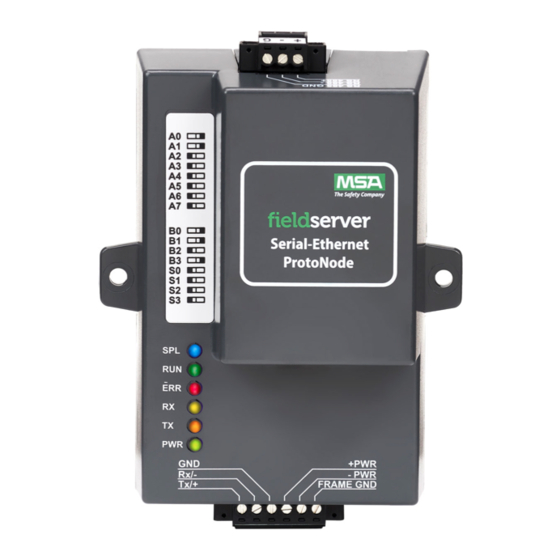
Page 7: Configure The Dip Switches
Configure the DIP Switches 2.4.1 Setting the Node/ID Device Instance (DIP Switch A0 – A7) • The A Bank DIP switches on the ProtoNode allow users to set the Node-ID/Device Instance on the Field RS-485. • DIP switches A0 – A7 can also be used to set the MAC Address for BACnet MS/TP and BACnet/IP. NOTE: When setting DIP Switches, please ensure that power to the board is OFF. -
Page 8: Select And Load Configuration Files
Baud Rate Dip Switch Selection Baud 9600 19200 38400* 57600 76800 * Factory default setting = 38400 2.4.3 Select and Load Configuration Files • The S bank of DIP switches, S0 - S3 is used to select and load a configuration file from a group of pretested/preloaded configuration files that the OEM has programmed for their end users. -
Page 9: Interfacing Protonode To Host Oem Device
Interfacing ProtoNode to Host OEM Device ProtoNode FPC-N34 and FPC-N35 Showing Connection Ports ProtoNode Start-up Guide... -
Page 10: Device Connections To Protonode
The top 3 pin port will always be R1, unless it’s a LonWorks ProtoNode in which case the port designation is LonWorks (and the port is 2 pins). The bottom 6 pin port will be R2. NOTE: The 6 pin port can be RS-232, RS-485 or KNX (and we use the left 3 pins for this as currently shown). Device Connections to ProtoNode ProtoNode 6 Pin Phoenix connector for RS-485 Devices •... -
Page 11: Resistor And Power Jumper Information
Resistor and Power Jumper Information 3.3.1 Bias Resistors The ProtoNode bias resistors are used to keep the RS-485 bus to a known state, when there is no transmission on the line (bus is idling), to help prevent false bits of data from being detected. The bias resistors typically pull one line high and the other low - i.e. -
Page 12: Termination Resistor
3.3.2 Termination Resistor Termination resistors are also used to reduce noise. These pull the two lines of an idle bus together. However, they would override the effect of any bias resistors, if connected. 3.3.3 Power Jumper Settings The ProtoNode power jumper is set to position A by default but can be changed to position B for other power supply requirements. -
Page 13: Wiring Field Port To Rs-485 Bms Network
Wiring Field Port to RS-485 BMS Network • Connect the RS-485 network wires to the 3-pin RS-485 connector on the ProtoNode FPC-N34 as shown below. ◦ Use standard grounding principles for RS-485 GND • If the ProtoNode is the last device on the trunk, then the end of line (EOL) termination switch needs to be enabled. See image below for the orientation of switch positions referenced below. -
Page 14: Power Up The Protonode
Power up the ProtoNode Apply power to ProtoNode as show below. Ensure that the power supply used complies with the specifications provided in Section 10.7 Specifications. • ProtoNode accepts either 9-30VDC or 12-24 VAC on pins 4 and 5. • Frame GND should be connected. -
Page 15: Connect The Pc To The Gateway
Connect the PC to the Gateway Connecting to the Gateway via Ethernet Connect a Cat-5 Ethernet cable (straight through or cross-over) between the local PC and ProtoNode . 5.1.1 Changing the Subnet of the Connected PC The default IP Address for the ProtoNode is 192.168.1.24, Subnet Mask is 255.255.255.0. If the PC and ProtoNode are on different IP networks, assign a static IP Address to the PC on the 192.168.1.xxx network. -
Page 16: Setup Web Server Security
Setup Web Server Security Login to the FieldServer The first time the FieldServer GUI is opened in a browser, the IP Address for the gateway will appear as untrusted. This will cause the following pop-up windows to appear. • When the Web Server Security Unconfigured window appears, read the text and choose whether to move forward with HTTPS or HTTP. - Page 17 • Additional text will expand below the warning, click the underlined text to go to the IP Address. In the example below this text is “Proceed to 10.40.50.94 (unsafe)”. • When the login screen appears, put in the Username (default is “admin”) and the Password (found on the label of the FieldServer).
-
Page 18: Select The Security Mode
Select the Security Mode On the first login to the FieldServer, the following screen will appear that allows the user to select which mode the FieldServer should use. NOTE: Cookies are used for authentication. NOTE: To change the web server security mode after initial setup, go to Section 10.4 Change Web Server Security Settings After Initial Setup. -
Page 19: Https With Own Trusted Tls Certificate
6.2.1 HTTPS with Own Trusted TLS Certificate This is the recommended selection and the most secure. Please contact your IT department to find out if you can obtain a TLS certificate from your company before proceeding with the Own Trusted TLS Certificate option. •... -
Page 20: Configure The Fieldserver
Configure the FieldServer Setting IP Address for Field Network • The Web Configurator will be displayed as the landing page. NOTE: Below the “Active Profiles” heading are listed the profiles for connected devices. If no profiles are present, then the wiring, baud rate, and DIP switch settings must be checked, because there is a problem with device communications. -
Page 21: Accessing The Fieldserver Manager
NOTE: The FieldServer Manager tab (see image above) allows users to connect to the Grid, MSA Safety’s device cloud solution for IIoT. The FieldServer Manager enables secure remote connection to field devices through a FieldServer and its local applications for configuration, management, maintenance. -
Page 22: Lonworks (Fpc-N35): Commissioning The Protonode On A Lonworks Network
LonWorks (FPC-N35): Commissioning the ProtoNode on a LonWorks Network Commissioning may only be performed by the LonWorks administrator. Commissioning theProtoNode FPC-N35 on a LonWorks Network During the commissioning process, the LonWorks administrator may prompt the user to hit the service pin on the ProtoNode FPC-N35 at a specific point (this step occurs at different points of the commissioning process for each LonWorks network management tool). - Page 23 • Open a web browser and go to the following address: [IP Address of ProtoNode]/fserver.xif ◦ Example: 192.168.1.24/fserver.xif • If the web browser prompts to save the file, save the file onto the PC. If the web browser displays the xif file as a web page, save the file on the local PC as “fserver.xif”.
-
Page 24: Troubleshooting
Troubleshooting Lost or Incorrect IP Address • Ensure that FieldServer Toolbox is loaded onto the local PC. Otherwise, download the FieldServer-Toolbox.zip via the MSA Safety website. • Extract the executable file and complete the installation. • Connect a standard Cat-5 Ethernet cable between the user’s PC and ProtoNode. -
Page 25: Viewing Diagnostic Information
Viewing Diagnostic Information • Type the IP Address of the FieldServer into the web browser or use the FieldServer Toolbox to connect to the FieldServer. • Click on Diagnostics and Debugging Button, then click on view, and then on connections. •... -
Page 26: Checking Wiring And Settings
Checking Wiring and Settings • No COMS on Modbus RTU side. If Tx/Rx are not flashing rapidly then there is a COM issue on the Modbus side. To fix this problem, check the following: ◦ Visual observations of LEDs on ProtoNode. (Section 9.5 LED Functions) ◦... -
Page 27: Taking A Fieldserver Diagnostic Capture
Taking a FieldServer Diagnostic Capture When there is a problem on-site that cannot easily be resolved, perform a Diagnostic Capture before contacting support. Once the Diagnostic Capture is complete, email it to technical support. The Diagnostic Capture will accelerate diagnosis of the problem. •... -
Page 28: Led Functions
LED Functions See the diagram below for ProtoNode FPC-N34 and FPC-N35 LED Locations. Description The SPL LED will light if the unit is not getting a response from one or more of the configured devices. For LonWorks units, LED will light until the unit is commissioned on the LonWorks network. The RUN LED will start flashing 20 seconds after power indicating normal operation. -
Page 29: Additional Information
Additional Information 10.1 Update Firmware To load a new version of the firmware, follow these instructions: 1. Extract and save the new file onto the local PC. 2. Open a web browser and type the IP Address of the FieldServer in the address bar. ◦... -
Page 30: Reading Data Arrays
10.3 Reading Data Arrays • Connect to the ProtoNode with a browser and click on the Diagnostics & Debugging button. • Select the User Messages branch. • Select the info tab. • See which profile has been loaded. ◦ Example: prof1b.csv •... -
Page 31: Change Web Server Security Settings After Initial Setup
10.4 Change Web Server Security Settings After Initial Setup NOTE: Any changes will require a FieldServer reboot to take effect. • Navigate from the ProtoNode landing page to the FS-GUI by clicking the blue “Diagnostics” text on the bottom of the screen. -
Page 32: Change Security Mode
10.4.1Change Security Mode • Click Security in the Navigation panel. • Click the Mode desired. ◦ If HTTPS with own trusted TLS certificate is selected, follow instructions in Section 6.2.1 HTTPS with Own Trusted TLS Certificate • Click the Save button. ProtoNode Start-up Guide... -
Page 33: Edit The Certificate Loaded Onto The Fieldserver
10.4.2Edit the Certificate Loaded onto the FieldServer NOTE: A loaded certificate will only be available if the security mode was previously setup as HTTPS with own trusted TLS certificate. • Click Security in the Navigation panel. • Click the Edit Certificate button to open the certificate and key fields. •... -
Page 34: Change User Management Settings
10.5 Change User Management Settings • From the FS-GUI page, click Setup in the Navigation panel. • Click User Management in the navigation panel. NOTE: If the passwords are lost, the unit can be reset to factory settings to reinstate the default unique password on the label. -
Page 35: Create Users
10.5.1Create Users • Click the Create User button. • Enter the new User fields: Name, Security Group and Password. ◦ User details are hashed and salted NOTE: The password must meet the minimum complexity requirements. An algorithm automatically checks the password entered and notes the level of strength on the top right of the Password text field. •... -
Page 36: Edit Users
10.5.2Edit Users • Click the pencil icon next to the desired user to open the User Edit window. • Once the User Edit window opens, change the User Security Group and Password as needed. • Click Confirm. • Once the Success message appears, click OK. ProtoNode Start-up Guide... -
Page 37: Delete Users
10.5.3Delete Users • Click the trash can icon next to the desired user to delete the entry. • When the warning message appears, click Confirm. ProtoNode Start-up Guide... -
Page 38: Change Fieldserver Password
10.5.4Change FieldServer Password • Click the Password tab. • Change the general login password for the FieldServer as needed. NOTE: The password must meet the minimum complexity requirements. An algorithm automatically checks the password entered and notes the level of strength on the top right of the Password text field. ProtoNode Start-up Guide... -
Page 39: Routing Settings
10.6 Routing Settings The Routing settings make it possible to set up the IP routing rules for the FieldServer’s internet and network connections. • Click the Add Rule button to add a new row and set a new Destination Network, Netmask and Gateway IP Address as needed. -
Page 40: Specifications
10.7 Specifications ProtoNode FPC-N34/N38 ProtoNode FPC-N35/N39 One 6-pin Phoenix connector with: One 6-pin Phoenix connector with: RS-485 port (+ / - / gnd) RS-485 port (+ / - / gnd) Power port (+ / - / Frame-gnd) Electrical Connections Power port (+ / - / Frame-gnd) One 3-pin Phoenix connector with: One Ethernet 10/100 BaseT port RS-485 port (+ / - / gnd) -
Page 41: Compliance With Ul Regulations
10.8 Compliance with UL Regulations For UL compliance, the following instructions must be met when operating the ProtoNode. • The units shall be powered by listed LPS or Class 2 power supply suited to the expected operating temperature range. • The interconnecting power connector and power cable shall: ◦... -
Page 42: A Bank Dip Switch Settings
10.9 A Bank DIP Switch Settings Address Address ProtoNode Start-up Guide... - Page 43 Address Address ProtoNode Start-up Guide...
- Page 44 Address Address ProtoNode Start-up Guide...
- Page 45 Address Address ProtoNode Start-up Guide...
-
Page 46: Limited 2 Year Warranty
Limited 2 Year Warranty MSA Safety warrants its products to be free from defects in workmanship or material under normal use and service for two years after date of shipment. MSA Safety will repair or replace any equipment found to be defective during the warranty period.
Need help?
Do you have a question about the fieldserver ProtoNode and is the answer not in the manual?
Questions and answers
Bacnet/IP.......BBMD setup. Need instructions
where can i purchase