Table of Contents
Advertisement
Quick Links
Advertisement
Table of Contents

Related Manuals for Inhep Digital Security IDS X Series

Summary of Contents for Inhep Digital Security IDS X Series
- Page 2 700-398-01J X-Series User Manual Issued for version 2.8x...
-
Page 3: Table Of Contents
Contents Introduction to the IDS X-Series Alarm Panel ..................6 Keypad Indicator Icons ....................... 8 Button Details ..........................8 Viewing Data on an LED Keypad ....................9 Numerical Values ........................9 Reading Binary Values ......................10 Entering Data on an LED Keypad ....................10 The Keypad Buzzer .......................... - Page 4 Identify Remote Receiver ......................33 Remote Receiver Test ....................... 34 Remote Receiver Capacity ......................35 LCD Keypad Zone Naming – Option 30 (Advanced) ................35 LCD Keypad Language – Option 31 ...................... 36 aXess ..............................36 Add/Edit Access Tags by number – Option 32 ................. 36 Option 33: Adding Access Tag by swiping the tag ..............
- Page 5 Glos sary Alarm Memory This is the history of the most recent events that occurred the last time the system was armed. Arming the system sets the system into the ARMED mode. In this mode, violating a zone will activate an alarm condition.
-
Page 6: Introduction To The Ids X-Series Alarm Panel
Introduction to the IDS X-Series Alarm Panel Congratulations on your purchase of an IDS Alarm Panel to protect your most valued possessions. The IDS X-series is a versatile and expandable range of alarm panels with 8 partitions and can be expanded to monitor up to 64 zones depending on the model. - Page 7 Figure 2: Curve LED Keypad Figure 3: Curve LCD Keypad 700-398-01J X-Series User Manual Issued for version 2.8x...
-
Page 8: Keypad Indicator Icons
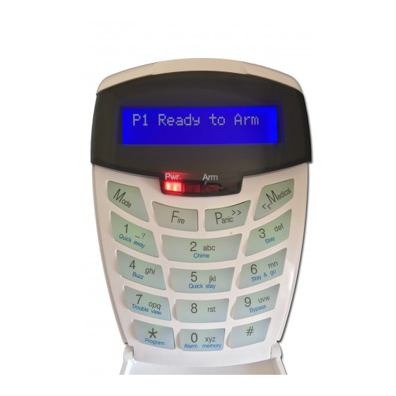
Figure 4: Touch Keypad LCD Display Power, Armed, Unarmed, Alarm Indicators Touch keys Keypad Indicator Icons Power indicator icon has two functions: When the icon is on, this indicates the keypad is powered up. Flashing indicates an issue has occurred and needs your attention. Armed icon indicates the system is armed either in ‘away’... -
Page 9: Viewing Data On An Led Keypad
Viewing Data on an LED Keypad Table 1 shows the LED status indicators and the meaning of their various states. Table 1: LED Indicators ARM LED READY LED POWER LED AWAY LED ZONE LED DESCRIPTION (red) (green) (red) (red) (amber) ... -
Page 10: Reading Binary Values
Reading Binary Values Values within a data program location will be displayed by the zone LEDs in binary coded decimal format i.e. zone LEDs 1-4 indicate units (ones) and zone LEDs 5-8 indicate tens (tens), and so on. To read a binary value on the keypad, add up the values represented by each lit LED as shown in Table 2. -
Page 11: The Keypad Buzzer
The Keypad Buzzer [#] WITH any key from [0] to [6] for 1 second The keypad includes a buzzer that is used for audible signalling and verification of certain keypad functions. There are 7 possible volume settings: loud being the default setting. To program the keypad volume, use Table Table 4: Keypad Buzzer Settings Key Entry Keypad Buzzer Sound... -
Page 12: Stay Arm
Stay Arm Stay arming allows the user to monitor selected perimeter zones and bypass interior zones. The user can remain on the premises with access to designated areas during the STAY ARM cycle. Any zone that may be violated accidentally should be programmed as a BUZZ ZONE. When violated, a BUZZ ZONE will cause the keypad buzzer to sound for 30 seconds before triggering the alarm and sounding the siren. -
Page 13: Key-Switch Or Remote Arming (If Fitted)
Q uic k Stay Arm Hold down the [5] key until the beep It is possible to STAY arm by holding down the [5] key until the keypad buzzer sounds. The panel will immediately arm into the stay mode without any exit delay. All stay zones will be bypassed. NOTE: Holding the button down again will cause the panel to toggle between stay profiles that have zones selected to be bypassed when stay armed. -
Page 14: Auto Arm
Auto Arm The panel may be programmed to arm automatically at a pre-programmed time. Should the premises be occupied at the time of auto-arming, a valid user code entered during the pre-arm delay will terminate the arming sequence. The pre-arm delay is signalled by an exit beep. NOTE: This can be enabled via the maintenance code, see page 32. -
Page 15: Fire Alarms
Enter the [ZONE NUMBER] followed by the [*] key. Alternatively you can use the [PANIC] or [MED] keys to scroll through the zones. (Y next to the zone number indicates that it has been bypassed and N not bypassed) Press the [*] key to toggle between zones being on and off. Repeat steps 6-8 to bypass/un-bypass other zones. -
Page 16: Alarm Memory
Alarm Memory Hold down the [0] key until the beep The Alarm Memory displays any zones that were violated, tampered with, or bypassed during the last arm cycle. A flashing ARM LED will notify you of an alarm. To view the alarm memory, disarm the panel and continue as follows: Hold down the [0] key until the keypad buzzer sounds. -
Page 17: User Program Mode
User Program Mode LED Keypad Hold down the [*] key until the beep, then enter [MASTER CODE] [*] [PROGRAMMABLE OPTION] [*] 1. Ensure that the panel is not armed. 2. Hold down the [*] key until the keypad buzzer sounds. 3. -
Page 18: Edit A Selected User Code - Option 1
5. A valid entry is confirmed by a long beep. An invalid entry will be signalled by means of an error beep (3 short beeps). If an error beep occurs, press the [#] key to clear all previous entries and repeat steps 1-4. 6. -
Page 19: Add/Edit Slot - Option 3
To select menu option 2 – ‘Delete User Code’, press the [2] key or alternatively use the [PANIC] or [MED] keys to scroll through the list of programmable options until you reach Menu Option 2. Press the [*] key. The LCD display reads ‘User Code + *’. Enter the [USER CODE] to be deleted followed by the [*] key. -
Page 20: View A User Code Slot Number - Option 5
LCD Keypad [*] [MASTER CODE] [*] [4] [*] [SLOT NUMBER] [*] [#] Enter the User Program Mode as per steps 1 - 4 of section User Program Mode. The LCD display reads ‘Option Menu’, ‘Add User Code’. To select menu option 4 – ‘Delete Slot’, press the [4] key, or alternatively use the [PANIC] or [MED] keys to scroll through the list of programmable options until you reach the option you want. - Page 21 Table 6: User Code Properties Zone LED Property Zone LED Property Master User Code Disarm Only Code Duress Code Global Arm/Disarm Code Arm to Disarm Code [Maid’s Code] Programmable Output Code Arm Only Code Voice Dial in enable LCD Keypad [*] [MASTER CODE] [*] [1] [0] [*] [USER CODE/SLOT] [*] [PROPERTY NUMBER] [*] [*] [#] 1.
-
Page 22: Assign A User Code To Partitions - Option 11 (Advanced)
P rogrammable Output Code This user property enables the use of various programmable outputs to perform home automation actions, such as turning on lights, switches, motors, etc. Any event which is able to trigger a programmable output can be assigned to an output number from 1 to 57. Assigning an event to outputs 1 to 5 will use the panel’s onboard outputs 1 to 5. -
Page 23: Allow The Installer Code To Access The User Menu - Option 12
Allow the Installer Code to Access the User Menu - Option 12 LED Keypad Hold down the [*] key until the beep, enter [MASTER CODE] [*] [1] [2] [*] [*] [#] Enter the User Program Mode as per steps 1 to 4 in section User Program Mode. Press the [1] [2] keys followed by the [*] key to select programmable option 12. -
Page 24: Xwave Bi-Directional Wireless
NOTE: If output action 0 is chosen, then LEDs 1 and 2 will be off. If output action 1 is chosen, then LED 1 will be on. If output action 2 is chosen, then LED 2 will be on. ... -
Page 25: Adding The Remote Transmitter To A User Code - Option 16
B i-D ire c tiona l Re mote Tr ans m itte r Each remote transmitter is learnt to a user code and will inherit that codes properties, i.e. arm/disarm, arm only, etc. Each remote transmitter has five buttons to control the alarm panel or can query alarm status. The default button assignments are indicated in Figure 4: Remote transmitter default button assignment below. -
Page 26: Deleting Bi-Directional Remote Transmitters - Option 18
Function Parameter Description Duress Disarm Partition No Will disarm the allocated partition and cause a duress condition in the alarm system and if configured the alarm will transmit the duress signal to the security company Panic Partition No Will cause the alarm to go into a panic condition and if configured the alarm will transmit the panic signal to the security company Medical Partition No... -
Page 27: Bi-Directional Pir Devices Walk Test Mode - Option 19
Bi-Directional PIR Devices Walk test mode – Option 19 Walk test mode will put certain capable devices into walk test mode from the X-Series keypad. Once in walk test mode the device will trigger continuously when an object has been detected and the LED will come on to indicate the detection. -
Page 28: Add Remote To Panel - Advanced
LED Keypad 1. Defaulting of the Remote Receiver is only for new installations of the Remote Receiver. 2. On the Alarm Panel, ADD the user codes that will be assigned to the Remote Receivers (one for each). Do this only if the codes have not already been entered before. 3. - Page 29 16. The keypad displays “…Confirming…”. 17. Release the remote button 18. The keypad displays “Success”, “Rt User R M B”. 19. Press the [*] key to return to steps 9-18 if you wish to add more remotes. 20. Once you have finished, press the [#] key to exit programming. NOTE: If you were unsuccessful, the keypad will display “fail”.
-
Page 30: Delete Remote From Panel
Delete Remote from Panel Use the following steps to add Remote Transmitters to the Remote Receiver connected to an IDS Alarm Panel via the Keypad Bus. [*] [Master Code] [*] [2] [2] [*] [Receiver Number] [*] [User Code] [*] [#] LCD Keypad 1. -
Page 31: Set Remote Receiver Relay Properties
LED Keypad 1. Hold the [*] key until the beep (3-4 seconds). 2. The READY and ARM LEDs flash alternately. 3. Enter [MASTER CODE] followed by the [*] key. 4. The READY LED flashes. 5. Enter [2] [3] followed by the [*] key. 6. -
Page 32: Set Remote Receiver Relay Pulse Time
Set Remote Receiver Relay Pulse Time Use the following steps to set the Remote Receiver relay pulse time. [*] [Master Code] [*] [2] [5] [Receiver Number] [*] [Relay Pulse Time] [*] [#] LCD Keypad 1. Hold the [*] key until the beep (3-4 seconds). 2. -
Page 33: Defaulting The Remote Receiver
Defaulting the Remote Receiver Use the following steps to default the Remote Receiver. [*] [Master Code] [*] [2] [6] [*] [Receiver Number] [*] [*] [#] LCD Keypad 1. Hold the [*] key until the beep (3-4 seconds). 2. The keypad displays “Master Code + *”. 3. -
Page 34: Remote Receiver Test
LED Keypad 1. Hold the [*] key until the beep (3-4 seconds). 2. The READY and ARM LEDs flash alternately. 3. Enter [MASTER CODE] followed by the [*] key. 4. The READY LED flashes. 5. Enter [2] [7] followed by the [*] key. 6. -
Page 35: Remote Receiver Capacity
Remote Receiver Capacity Use the following steps to view the capacity of the Remote Receiver. [*] [Master Code] [*] [2] [9] [*] [Receiver Number] [*] [#] LCD Keypad Hold the [*] key until the beep (3-4 seconds). The keypad displays “Master Code + *”. Enter [MASTER CODE] followed by the [*] key. -
Page 36: Lcd Keypad Language - Option 31
The [PANIC] and [MED] keys may be used to scroll right or left through the name respectively. The [MODE] key is used to toggle between upper and lower case. 9. Pressing the [#] key will reset the zone name to [Zone Number] if a character has been entered. If no character has been entered, then pressing [#] will exit zone name programming and return to the options menu. -
Page 37: Delete Access Tags Via Swipe - Option 35
Delete Access Tags via Swipe - Option 35 This menu option allows the user to remove a card from the reader if the card is available [*] [MASTER CODE] [*] [3] [5] [*] [Door No] [*] [Swipe Tag] [*] [#] Enter [3][5][*] Enter the door number that the action will be carried out [Door No] [*]. - Page 38 Table 12: Access Reader Only LED Descriptions ARMING ONLY READER Action Description..Yellow Green Beeper All 3 LED's flashing in sync None Factory Reset Flashing in sync with Flashing out of sync Flashing in sync with Single beep when any tag Green LED with Red/Green Red LED...
-
Page 39: Serial Code - Option 37 (X-Series 2.72 & Above)
Serial Code – Option 37 (X-Series 2.72 & above) Once a device has been connected to the serial bus and powered on a six digit code must be entered for communication to take place between the X-series alarm and the new serial device. Note: This option can only be accessed via an LCD keypad. -
Page 40: Edit The Date - Option 41
LCD Keypad [*] [MASTER CODE] [*] [4] [0] [*] [TIME] [*] [#] 1. Enter the User Program Mode as per steps 1 - 4 of section User Program Mode 2. The LCD display reads ‘Option Menu’, ‘Add User Code’. 3. To select menu option 40, ‘Edit Time’, press the [4] [0] keys followed by the [*] key or alternatively use the [PANIC] or [MED] keys to scroll through the list of programmable options to option 40. -
Page 41: How To Select A Stay Profile
How to Select a Stay Profile Quick Select Method (LCD only): Press the [5] key simultaneously with the [STAY PROFILE NUMBER] and release 1. Ensure that the Panel is disarmed. 2. Press the [#] key to clear any previous entries. 3. -
Page 42: Buzz Zones
NOTE: Buzz zones will be shown by flashing LEDs. (See Section How to Program Stay Zones). A Buzz zone cannot be selected as a Stay Zone. The Buzz status must be cleared first. 7. Repeat steps 4 - 6 until the all the required Stay zones are programmed/cancelled. 8. -
Page 43: How To Program Chime Zones
How to Program Chime Zones LED Keypad Hold down the [2] key until the beep, then enter [ZONE NUMBER] [*] [#] 1. Hold down the [2] key until the keypad buzzer sounds. 2. The POWER LED turns off. 3. Entering a zone number will toggle the corresponding LED. For example, [2] [*] will toggle LED 2 on if off or off if on. -
Page 44: Explanation Of Trouble Conditions
Explanation of Trouble Conditions Panel AC Supply Failure This occurs when your Alarm Panel does not receive any power from your mains electricity. Causes of this can be a power failure, or your transformer is not plugged in or faulty. Your alarm company might not receive your panic or alarm signal. -
Page 45: Changing A Partition
Zone Tamper A device wired or wireless has been interfered with, either opened or removed from its mountings, etc. Changing a Partition Hold down the [MODE] key until the beep, then enter [1] [*] [PARTITION NUMBER] [*] To change the partition you are currently viewing, the keypad must be a global keypad. 1. -
Page 46: Maintenance Code - Advanced
Maintenance Code - Advanced The maintenance code, by default is 8888 or 888888 can be used by a user (without requiring help from an installer) to access and program a limited number of installer locations. This may be desired by a high-level user who requires low-level access to certain limited installer locations within the Alarm Panel. - Page 47 L OCAT ION 25 Month to Start D aylig ht Saving (de fault = 0) Select the month for Daylight Saving to commence, as per Table 17. Table 15: Month Data Value Month Value Month Value Month Value Month Disabled April July October...
- Page 48 L OCAT ION 165 N o Move m e nt Auto Arm T im e Out (de fault = 000 0) If no violations are registered for the period of time specified in this location then the alarm will auto arm. This may be used if you forget to arm when leaving for work;...
- Page 49 L OCAT ION 171 to 178 N o Move m e nt Auto Arm/Me dic al Alarm D ays Choose which days of the week that you want the, arm on no movement or medical alarm to be enabled. Table 18: Arm/ Medical Days Data ARM Days of the Week Medical Days of the Week Monday...
-
Page 50: Programming Quick Reference Guide
Programming Quick Reference Guide Quick Reference User Guide NOTE: The first key pressed in any programming sequence needs to be held down until the beep is heard. Description Programming Add a User Code [*] [Master Code] [*] [0] [*] [New Code] [*] Edit a User Code [*] [Master Code] [*] [1] [*] [Old Code] [*] [New Code] [*] Delete a User Code by Code... - Page 51 700-398-01J X-Series User Manual Issued for version 2.8x...
-
Page 52: Led Keys
LED Keys Key Action LED status Action [2] Chime READY on Alarm READY on Memory [3] Stay READY on User Menu READY & ARM flashing alternately [4] Buzz READY on [MODE] Mode READY flashing [7] Trouble AWAY, ARM, READY flashing Medical View simultaneously...
Need help?
Do you have a question about the IDS X Series and is the answer not in the manual?
Questions and answers